The MEMS Handbook (1st Ed) - M. Gad el Hak Part 13 pps
Bạn đang xem bản rút gọn của tài liệu. Xem và tải ngay bản đầy đủ của tài liệu tại đây (130.49 KB, 3 trang )
© 2002 by CRC Press LLC
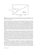
of this micro-velocity-sensor was tested in a two-dimensional, flat-plate boundary layer at a Reynolds
number based on distance from the leading edge of 4.2 × 10
6
. Figure 16.12 compares the mean velocity
profile in a turbulent boundary layer as measured with a conventional and MEMS-based sensor. The
microsensor measured mean velocities with the same accuracy as a corresponding conventional hot-wire.
Moreover, it was also demonstrated that the microsensor had spatial and temporal resolutions that made it
suited for turbulence measurements. Figure 26.13 shows the streamwise turbulence intensity and the
Reynolds stress as measured by a conventional X-wire and by two silicon microsensors. The MEMS-
based sensors operated with good resolution even when the temperature of the heated part was reduced
considerably. A clear drawback of this micro-hot-film is the proximity of the heated part of the sensor
to the surface of the chip, rendering the probe insensitive to changes in flow direction. This makes the
silicon sensor unsuited for use in three-dimensional flows where the primary flow direction is not known
a priori.
Jiang et al. (1994) presented a MEMS-based velocity sensor with the hot-wire freestanding in space
without any nearby structures, so that cooling velocities can be determined in the same way as with a
conventional hot-wire. Their sensor is shown in Figure 26.14 and has a polysilicon hot-element that is
greatly reduced in size, typically about 0.5
µm thick, 1 µm wide, and 10–160 µm long. The dynamic
performance and sensitivity of this sensor have been tested. A heating time of 2
µs and a cooling time of
8
µs for the 30-µm-long sensor in constant-current mode have been achieved. For constant-temperature
operation, a time constant of 0.5
µs for the 10-µm-long sensor has been recorded. The corresponding
cut-off frequency is 1.4 MHz. The calibration curves of a 20-
µm-long micro-hot-wire at two different
angles are shown in Figure 26.15. The average sensitivity was found to be 20 mV/m/s at an input current
of 0.5 mA. No turbulence measurements have been reported using this sensor. Noteworthy is that the
silicon hot-wires have a trapezoidal cross section, which might cause severe uncontrolled errors in turbulence
measurements.
A severe drawback of commercially available triple hot-wire probes is the large measuring volume,
typically a sphere with a diameter of 3 mm. This is far too large to be acceptable for turbulence
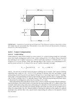
measurements at realistic Reynolds numbers. Ebefors et al. (1998) have presented a MEMS-based triple-
hot-wire sensor, shown schematically in Figure 26.16. The x- and y-hot-wires are located in the wafer
plane while the z-wire is rotated out of the plane using a radial polyimide joint. The silicon chip size is
3.5 × 3.0 × 0.5 mm
3
, and the three wires are each 500 × 5 × 2 µm
3
. The sensor is based on the thermal
anemometer principle, and the polyimide microjoint technique is used to create a well-controlled,
FIGURE 26.12 Typical mean velocity profile measured with a MEMS sensor and a conventional single hot-wire.
Here, U/u
τ
= f (u
τ
y/v), where u
τ
is the friction velocity. (From Löfdahl, L. et al. (1992) Exp. Fluids, 12, 391–393. © 1992
Springer-Verlag. With permission.)
U
+
= U/u
τ
0
110
U
+
= y
+
100 1000
Hot-wire
Silicon sensor
10
20
30
y
+
= u
τ
y/ν
U
+
= ln y
+
+ 5.0
1
0.41
© 2002 by CRC Press LLC
of this micro-velocity-sensor was tested in a two-dimensional, flat-plate boundary layer at a Reynolds
number based on distance from the leading edge of 4.2 × 10
6
. Figure 16.12 compares the mean velocity
profile in a turbulent boundary layer as measured with a conventional and MEMS-based sensor. The
microsensor measured mean velocities with the same accuracy as a corresponding conventional hot-wire.
Moreover, it was also demonstrated that the microsensor had spatial and temporal resolutions that made it
suited for turbulence measurements. Figure 26.13 shows the streamwise turbulence intensity and the
Reynolds stress as measured by a conventional X-wire and by two silicon microsensors. The MEMS-
based sensors operated with good resolution even when the temperature of the heated part was reduced
considerably. A clear drawback of this micro-hot-film is the proximity of the heated part of the sensor
to the surface of the chip, rendering the probe insensitive to changes in flow direction. This makes the
silicon sensor unsuited for use in three-dimensional flows where the primary flow direction is not known
a priori.
Jiang et al. (1994) presented a MEMS-based velocity sensor with the hot-wire freestanding in space
without any nearby structures, so that cooling velocities can be determined in the same way as with a
conventional hot-wire. Their sensor is shown in Figure 26.14 and has a polysilicon hot-element that is
greatly reduced in size, typically about 0.5
µm thick, 1 µm wide, and 10–160 µm long. The dynamic
performance and sensitivity of this sensor have been tested. A heating time of 2
µs and a cooling time of
8
µs for the 30-µm-long sensor in constant-current mode have been achieved. For constant-temperature
operation, a time constant of 0.5
µs for the 10-µm-long sensor has been recorded. The corresponding
cut-off frequency is 1.4 MHz. The calibration curves of a 20-
µm-long micro-hot-wire at two different
angles are shown in Figure 26.15. The average sensitivity was found to be 20 mV/m/s at an input current
of 0.5 mA. No turbulence measurements have been reported using this sensor. Noteworthy is that the
silicon hot-wires have a trapezoidal cross section, which might cause severe uncontrolled errors in turbulence
measurements.
A severe drawback of commercially available triple hot-wire probes is the large measuring volume,
typically a sphere with a diameter of 3 mm. This is far too large to be acceptable for turbulence
measurements at realistic Reynolds numbers. Ebefors et al. (1998) have presented a MEMS-based triple-
hot-wire sensor, shown schematically in Figure 26.16. The x- and y-hot-wires are located in the wafer
plane while the z-wire is rotated out of the plane using a radial polyimide joint. The silicon chip size is
3.5 × 3.0 × 0.5 mm
3
, and the three wires are each 500 × 5 × 2 µm
3
. The sensor is based on the thermal
anemometer principle, and the polyimide microjoint technique is used to create a well-controlled,
FIGURE 26.12 Typical mean velocity profile measured with a MEMS sensor and a conventional single hot-wire.
Here, U/u
τ
= f (u
τ
y/v), where u
τ
is the friction velocity. (From Löfdahl, L. et al. (1992) Exp. Fluids, 12, 391–393. © 1992
Springer-Verlag. With permission.)
U
+
= U/u
τ
0
110
U
+
= y
+
100 1000
Hot-wire
Silicon sensor
10
20
30
y
+
= u
τ
y/ν
U
+
= ln y
+
+ 5.0
1
0.41
© 2002 by CRC Press LLC
27
Surface-Micromachined
Mechanisms
27.1 Introduction
27.2 Material Properties and Geometric Considerations
Stress and Strain • Young’s Modulus • Poisson’s Ratio • Contact
Stresses • Stress in Films and Stress Gradients • Wear • Stiction
27.3 Machine Design
Compliance Elements—Columns, Beams and Flexures •
Columns • Beams • Stress Concentration • Cantilever Beam
Springs • Fixed Beam Springs • Flexures • Springs in
Combinations • Buckling
27.4 Applications
Microengine • Countermeshing Gear Discriminator
• Micro-Flex Mirror
27.5 Failure Mechanisms in MEMS
Vertical Play and Mechanical Interference in Out-of-Plane
Structures • Electrical Shorts • Lithographic Variations •
Methods of Increasing the Reliability of Mechanisms
Acknowledgments
27.1 Introduction
Surface-micromachining technologies have offered the following advantages to mechanism users and
designers: smaller machines, different physical effects that dominate at the microscale, and reduced
assembly costs. The advantages of smaller machines are sometimes very important. For example, small
machines are important in aviation and space applications where a decrease in size and weight corre-
sponds to an increased range or a reduction in the amount of fuel required for a given mission. The
advantages of the different physical effects that dominate at the microscale are less obvious. Mechanisms
that operate at high frequencies can greatly benefit (or suffer) from the reduced influence of inertia
(typical of surface-micromachined devices) if the aim is to start and stop quickly. Smaller scales also
mean surface-micromachined mechanisms are more resistant to shock and vibration than macrosized
mechanisms because the component strength decreases as the square of the dimensions while the mass
and inertia decrease as the cube of the dimensions. Another difference is that forces, such as van der
Waals forces and electrostatic attraction, are much more important at the microscale than at the macro-
scale. Reduced assembly costs are another advantage of surface-micromachined mechanisms. Surface
micromachining in most cases allows the creation of machines that are assembled at the same time as
their constituent components. Instead of using skilled workers to assemble intricate mechanisms by hand
or investing in complicated machinery, the assembly is done as a batch process during the integrated-
circuit-derived fabrication process. Preassembly does impose certain limitations on the designer, such as
the inability to build devices with as-fabricated stored mechanical energy. Instead, structures such as
Andrew D. Oliver
Sandia National Laboratories
David W. Plummer
Sandia National Laboratories