The MEMS Handbook (1st Ed) - M. Gad el Hak Part 14 potx
Bạn đang xem bản rút gọn của tài liệu. Xem và tải ngay bản đầy đủ của tài liệu tại đây (194.57 KB, 5 trang )
© 2002 by CRC Press LLC
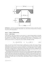
amount of backlash built into the system. A third problem relates to the ability of the hinge to pivot.
Often there is not a large rotational moment to rotate the mirror out of plane when planar hinged
structures are connected to planar-surface-micromachined actuators. This means that the designer must
take great care to ensure that the hinge always rotates in the correct direction.
27.5 Failure Mechanisms in MEMS
One of the most effective ways we can learn is to learn from our own mistakes. This can be a memorable
experience but in the field of MEMS it can be a very expensive and inefficient one. One reason is that
the time between design completion and testing is usually measured in months and the price per fabri-
cation run is many thousands of dollars. As of the year 2000, there were only rudimentary modeling and
simulation tools available for surface-micromachined mechanisms. This section seeks to share learning
obtained at the expense of others by describing some mechanical failures in surface-micromachined
mechanisms. The hope is that the reader will gain a deeper appreciation for the complexities of surface-
micromachined mechanism design and learn about some of the pitfalls.
27.5.1 Vertical Play and Mechanical Interference
in Out-of-Plane Structures
Surface-micromachined parts typically have a thickness that is very small in relationship to their width or
breadth. In the out-of-plane direction, the thickness is limited to a few micrometers due to the limited
deposition rates of low-pressure chemical vapor deposition (LPCVD) systems and the stresses in the
deposited films. In the plane of the substrate, structures can be millimeters across. These factors typically
lead to surface-micromachined structures that have a very small aspect ratio as well as stiffness issues in
the out-of-plane direction due to the limited thickness of the parts. The result is that designers of surface-
micromachines need to design structures in three dimensions and account for potential movements out of
the plane of the substrate. One instance of a potential problem is when gears fabricated in the same structural
layer of polysilicon fail to mesh because one or both of the gears are tilted. Another is when structures
moving above or below another structure mechanically interfere with each other when it was the intended
for them to clear each other without touching. Both of these instances will be examined separately.
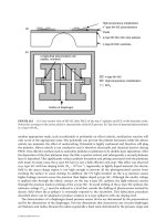
An example of the out-of-plane movement of gears is illustrated in Figure 27.26. In this instance, the
driven gear in the top of the figure has been wedged underneath the large load gear at the bottom of the
photograph. The way to prevent this situation is to understand the forces that create the out-of-plane motion
FIGURE 27.26 The gear teeth of the small gear are wedged underneath the teeth of the large diameter gear. In this
case, gear misalignment is about 2.5
µm in the vertical direction.
© 2002 by CRC Press LLC
amount of backlash built into the system. A third problem relates to the ability of the hinge to pivot.
Often there is not a large rotational moment to rotate the mirror out of plane when planar hinged
structures are connected to planar-surface-micromachined actuators. This means that the designer must
take great care to ensure that the hinge always rotates in the correct direction.
27.5 Failure Mechanisms in MEMS
One of the most effective ways we can learn is to learn from our own mistakes. This can be a memorable
experience but in the field of MEMS it can be a very expensive and inefficient one. One reason is that
the time between design completion and testing is usually measured in months and the price per fabri-
cation run is many thousands of dollars. As of the year 2000, there were only rudimentary modeling and
simulation tools available for surface-micromachined mechanisms. This section seeks to share learning
obtained at the expense of others by describing some mechanical failures in surface-micromachined
mechanisms. The hope is that the reader will gain a deeper appreciation for the complexities of surface-
micromachined mechanism design and learn about some of the pitfalls.
27.5.1 Vertical Play and Mechanical Interference
in Out-of-Plane Structures
Surface-micromachined parts typically have a thickness that is very small in relationship to their width or
breadth. In the out-of-plane direction, the thickness is limited to a few micrometers due to the limited
deposition rates of low-pressure chemical vapor deposition (LPCVD) systems and the stresses in the
deposited films. In the plane of the substrate, structures can be millimeters across. These factors typically
lead to surface-micromachined structures that have a very small aspect ratio as well as stiffness issues in
the out-of-plane direction due to the limited thickness of the parts. The result is that designers of surface-
micromachines need to design structures in three dimensions and account for potential movements out of
the plane of the substrate. One instance of a potential problem is when gears fabricated in the same structural
layer of polysilicon fail to mesh because one or both of the gears are tilted. Another is when structures
moving above or below another structure mechanically interfere with each other when it was the intended
for them to clear each other without touching. Both of these instances will be examined separately.
An example of the out-of-plane movement of gears is illustrated in Figure 27.26. In this instance, the
driven gear in the top of the figure has been wedged underneath the large load gear at the bottom of the
photograph. The way to prevent this situation is to understand the forces that create the out-of-plane motion
FIGURE 27.26 The gear teeth of the small gear are wedged underneath the teeth of the large diameter gear. In this
case, gear misalignment is about 2.5
µm in the vertical direction.
© 2002 by CRC Press LLC
28
Microrobotics
28.1 Introduction
MEMS as the Motivation for Robot Miniaturization
28.2 What is Microrobotics?
Task-Specific Definition of Microrobots • Size- and
Fabrication-Technology-Based Definitions of Microrobots •
Mobility- and Functional-Based Definition of Microrobots
28.3 Where To Use Microrobots?
Applications for MEMS-Based Microrobots • Microassembly
28.4 How To Make Microrobots?
Arrayed Actuator Principles for Microrobotic
Applications • Microrobotic Actuators and Scaling
Phenomena • Design of Locomotive Microrobot Devices
Based on Arrayed Actuators
28.5 Microrobotic Devices
Microgrippers and Other Microtools • Microconveyers •
Walking MEMS Microrobots
28.6 Multirobot System (Microfactories
and Desktop Factories)
Microrobot powering • Microrobot communication
28.7 Conclusion and Discussion
28.1 Introduction
28.1.1 MEMS as the Motivation for Robot Miniaturization
The microelectromechanical systems (MEMS) field has traditionally been dominated by silicon micro-
machining. In the early days, efforts were concentrated on fabricating various silicon structures and
relatively simple components and devices were then developed. For describing this kind of microelec-
tromechanical
structures
the acronym MEMs is used. A growing interest in manufacturing technologies
other than the integrated circuit (IC)-inspired silicon wafer and batch MEMs fabrication is evident in
the microsystem field today. This interest in alternative technologies has surfaced with the desire to use
new MEMs materials, that enable a greater degree of geometrical freedom than materials that rely on
planar photolithography as a means to define the structure. One such new MEMs material is plastic,
which can be used to produce low-cost, disposable microdevices through microreplication. The micro-
machining field has also matured and grown from a technology used to produce simple devices to a
technology used for manufacturing complex miniaturized systems which has shifted the acronym from
representing
structures
to microelectromechanical
systems
. Microsystems encompass microoptical systems
(microoptoelectromechanical systems, MOEMS), microfluidics (micro-total analysis systems,
µ
-TAS) etc.
These systems contain micromechanical components including moveable mirrors and lenses, sensors,
light sources, pumps and valves and passive components such as optical and fluidic waveguides, as well
as electrical components and power sources of various types.
Thorbjörn Ebefors
Royal Institute of Technology
Göran Stemme
Royal Institute of Technology
© 2002 by CRC Press LLC
29
Microscale Vacuum
Pumps
29.1 Introduction
29.2 Fundamentals
Basic Principles • Conventional Types of Vacuum
Pumps • Pumping Speed and Pressure Ratio • Definitions
for Vacuum and Scale
29.3 Pump Scaling
Positive-Displacement Pumps • Kinetic Pumps • Capture
Pumps • Pump-Down and Ultimate Pressures for MEMS
Vacuum Systems • Operating Pressures and
Requirements
in MEMS Instruments • Summary of Scaling Results
29.4 Alternative Pump Technologies
Outline of Thermal Transpiration Pumping
• Accommodation Pumping
29.5 Conclusions
Acknowledgments
29.1 Introduction
Numerous potential applications for meso- and microscale sampling instruments are based on mass
spectrometry [Nathanson et al., 1995; Ferran and Boumsellek, 1996; Orient et al., 1997; Piltingsrud,
1997; Wiberg et al., 2000; White et al., 1998; Freidhoff et al., 1999; Short et al., 1999] and gas chroma-
tography [Terry et al., 1979]. Other miniaturized instruments utilizing electron optics [Chang et al., 1990;
Park et al., 1997; Callas, 1999] will require both high-vacuum and repeated solid-sample transfers from
higher pressure environments. The mushrooming interest in chemical laboratories on chips will likely
evolve toward some manifestations requiring vacuum capabilities. At present, there are no microscale or
mesoscale vacuum pumps to pair with the embryonic instruments and laboratories that are being devel-
oped. Certainly, small vacuum pumps will not always be necessary. Some of the new devices are attractive
because of low quantities of waste and rapidity of analysis, not directly because they are small, energy
efficient, or portable. However, for other applications involving portability and/or autonomous opera-
tions, appropriately small vacuum pumps with suitably low power requirements will be necessary. This
chapter addresses the question of how to approach providing microscale and mesoscale vacuum pumping
capabilities consistent with the volume and energy requirements of meso- and microscale instruments and
processes in need of similarly sized vacuum pumps. It does not review existing microscale pumping devices
because none are available with attractive performance characteristics (a review of the attempts has recently
been presented by Vargo, 2000; see also NASA/JPL, 1999).
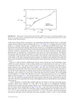
In the macroscale world, vacuum pumps are not very efficient machines, ranging in thermal efficiencies
from very small fractions of one percent to a few percent. They generally do not scale advantageously to
N
˙
E. Phillip Muntz
University of Southern California
Stephen E. Vargo
SiWave, Inc.
© 2002 by CRC Press LLC
30
Microdroplet Generators
30.1 Introduction
30.2 Operation Principles of Microdroplet Generators
Pneumatic Actuation • Piezoelectric Actuation •
Thermal-Bubble Actuation • Thermal-Buckling
Actuation • Acoustic-Wave Actuation • Electrostatic
Actuation • Inertial Actuation
30.3 Physical and Design Issues
Frequency Response • Thermal/Hydraulic Cross-Talk and
Overfill • Satellite Droplets • Puddle Formation • Material
Issues
30.4 Fabrication of Microdroplet Generators
Multiple Pieces • Monolithic Fabrication
30.5 Characterization of Droplet Generation
Droplet Trajectory • Ejection Direction • Ejection
Sequence/velocity and Droplet Volume • Flow Field
Visualization
30.6 Applications
Inkjet Printing • Biomedical and Chemical Sample
Handling • Fuel Injection and Mixing Control • Direct
Writing and Packaging • Optical Component Fabrication
and Integration • Solid Freeforming • Manufacturing
Process • Integrated Circuit Cooling
30.7 Concluding Remarks
30.1 Introduction
Microdroplet generators are becoming an important research area in microelectromechanical systems
(MEMS), not only because of the valuable marketing device—inkjet printhead—but also because of the
many other emerging applications for precise or micro-amount fluidic control. There has been a long
history of development of microdroplet generators ever since the initial inception by Sweet (1964, 1971),
who used piezo actuation, and by Hewlett-Packard and Cannon [Nielsen et al., 1985] in the late 1970s,
who used thermal bubble actuation. Tremendous research activities regarding inkjet applications have
been devoted to this exciting field. Emerging applications in the biomedical, fuel-injection, chemical,
pharmaceutical, electronic fabrication, microoptical device, integrated circuit cooling, and solid freeform
fields have fueled these research activities. Thus, many new operation principles, designs, fabrication
processes and materials related to microdroplet generation have been explored and developed recently,
supported by micromachining technology.
In this chapter, microdroplet generators are defined as droplet generators generating microsized
droplets in a controllable manner; that is, droplet size and number can be accurately controlled and
counted. Thus, atomizer, traditional fuel-injector or similar droplet-generation devices that do not offer
such control are not discussed here.
Fan-Gang Tseng
National Tsing Hua University