The MEMS Handbook Introduction & Fundamentals (2nd Ed) - M. Gad el Hak Part 10 pps
Bạn đang xem bản rút gọn của tài liệu. Xem và tải ngay bản đầy đủ của tài liệu tại đây (1.73 MB, 30 trang )
microfabricated rotor (a cylinder of density
ρ
, diameter D, and length L) compared to the pressure (p)
acting on its projected surface area. This can be expressed as a non-dimensional load parameter:
ζ
ϭ
∝
(11.1)
from which it can be seen that the load parameter decreases linearly as the device shrinks. For example,
the load parameter due to the rotor mass for the MIT Microengine, which is a relatively large MEMS
devices (measuring 4 mm in diameter and 300 microns deep), is approximately 10
Ϫ3
. The benefits of this
scaling are that orientation or the freely suspended part becomes effectively irrelevant and that unloaded
operation is easy to accomplish. In addition, since the gravity loading is negligible, the primary forces that
one needs to support are pressure-induced loads and in a rotating device loads due to rotational imbal-
ance. This last load is very important and will be discussed in more detail in connection to rotating lubri-
cation requirements. The chief disadvantage of the low natural loading is that unloaded operation is often
undesirable (in hydrodynamic lubrication where a minimum eccentricity is required for journal bearing
stability), and in practice, gravity loading is often used to advantage. Therefore a scheme for applying an
artificial load needs to be developed. This is discussed in more detail later in the chapter.
11.2.2 Applicability of the Continuum Hypothesis
A common concern in microfluidic devices is the appropriateness of the continuum hypothesis as the
device scale continues to fall. At some scale, the typical inter-molecular distances will be comparable to
the device scales and the use of continuum fluid equations becomes suspect. For gases, this is measured
by the Knudsen number (Kn) — the ratio of the mean free path to the typical device scale. Numerous
experiments [Arkilic et al., 1997, 1993; Breuer et al., 2001] have determined that non-continuum effects
become observable when Kn reaches approximately 0.1 and that continuum equations become meaning-
less (the “transition flow regime”) at Kn of approximately 0.3. For atmospheric temperature and pressure,
the mean free path of air is approximately 70nm. Thus, atmospheric devices with features smaller than
approximately 0.2 microns will be subject to non-negligible non-continuum effects. In many cases, such
small dimensions are not present, and the fluidic analysis can safely use the standard Navier–Stokes equa-
tions (this is the case for the microengine).
Nevertheless, in applications where viscous damping is to be avoided (for example in high-Q resonat-
ing devices such as accelerometers or gyroscopes) the operating gaps are typically quite small (perhaps a
few microns), and the gaps serve as both a physical standoff and a sense-gap where capacitive sensing is
accomplished. In such examples one must work with the small dimension, and in order to minimize vis-
cous effects, the device is packaged at low pressures where non-continuum effects are evident. For small
Knudsen numbers, the Navier–Stokes equations can be used with a single modification — the boundary
condition is relaxed from the standard non-slip condition to that of a slip-flow condition where the
velocity at the wall is related to the Knudsen number and the gradient of velocity at the wall:
u
w
ϭ
λ
Έ
w
(11.2)
where
σ
is the tangential momentum accommodation coefficient (TMAC) which varies between 0 and 1.
Experimental measurements [Breuer et al., 2001] indicate that smooth native silicon has a TMAC of
approximately 0.7 in contact with several commonly used gases.
Despite the fact that the slip-flow theory is valid only for low Kn, it is often used incorrectly with great
success at much higher Knudsen numbers. Its adoption beyond its range of applicability stems primarily
from the lack of any better approach short of solving the Bolzmann equation or Direct Simulation Monte
Carlo (DSMC) computations [Beskok and Karniadakis, 1994; Cai et al., 2000]. For many simple geome-
tries, the “extended” slip-flow theory works much better than it should and provides quite adequate results
[Kwok et al., 2005]. This theory is demonstrated in the sections on Couette and squeeze-film damping
later in the chapter.
∂u
ᎏ
∂y
2 Ϫ
σ
ᎏ
σ
D
ᎏ
p
ρπ
LD
2
/4
ᎏ
pLD
Lubrication in MEMS 11-3
© 2006 by Taylor & Francis Group, LLC
11-4 MEMS: Introduction and Fundamentals
11.2.3 Surface Roughness
Another peculiar feature of MEMS devices is that the surface roughness of the material used can become
a significant factor in the overall device geometry. MEMS surface finishes are quite varied, ranging from
atomically smooth surfaces found on polished single-crystal silicon substrates to the rough surfaces left
by different etching processes. The effects of these topologies can be important in several areas for microde-
vice performance. Probably the most important effect is the way in which the roughness can affect struc-
tural characteristics such as crack initiation, yield strength, etc., although this will not be explored in this
chapter. Secondly, the surface finish can affect fluidic phenomena such as the energy and momentum
accommodation coefficient, and consequently, the momentum and heat transfer. Lastly, the surface char-
acteristics (not only the roughness, but also the surface chemistry and affinity) can strongly affect its
adhesive force. This is not treated in detail in this discussion, although it is mentioned briefly at the end
of the chapter in connection with tribology issues in MEMS.
11.3 Governing Equations for Lubrication
With the proviso that the continuum hypothesis holds for micron-scale devices (perhaps with a modified
boundary condition), the equations for microlubrication are identical to those used in conventional
lubrication analysis and can be found in any standard lubrication textbook [Hamrock, 1984]. We present
the essential results here, but the reader is referred to more complete treatments for full derivations and
a detailed discussion of the appropriate limitations.
Starting with the Navier–Stokes equations, we can make a number of simplifying assumptions appro-
priate for lubrication problems. These are itemized here:
Inertia: The terms representing transfer of momentum due to inertia may be neglected. This arises
because of the small dimensions that characterize lubrication geometries and MEMS in particular.
In very high speed devices such as the MIT Microengine, inertial terms may not be as small as one
might like, and corrections for inertia may be applied. However, preliminary studies suggest that these
corrections are small [Piekos, 2000].
Curvature: Lubrication geometries are typically characterized by a thin fluid film with a slowly varying
film thickness. The critical dimension in such systems is the film thickness, and this is assumed to
be much smaller than any radius of curvature associated with the overall system. This assumption is
particularly important in rotating systems where a circular journal bearing is used. Assuming that
the radius of the bearing R is much larger than the typical film thickness c (i.e., c/R ϽϽ 1) greatly
simplifies the governing equations.
Isothermal: Because volumes are small and surface areas are large, thermal contact between the fluid and
the surrounding solid is very good in a MEMS device. In addition, common MEMS materials are good
thermal conductors. For both these reasons, it is safe to assume that the lubrication film is isothermal.
With these restrictions, the Navier–Stokes equations, the equation for the conservation of mass, and
the equation of state for a perfect gas may be combined to yield the Reynolds equation [Reynolds, 1886],
written here for two-dimensional films:
0 ϭ
Ϫ
ϩ
Ϫ
ϩ
ϩ
ϩ
ρ
(w
a
Ϫ w
b
) Ϫ
ρ
u
a
Ϫ
ρ
v
a
ϩ h (11.3)
where x and y are the coordinates in the lubrication plane: u
a
etc. are the velocities of the upper
and lower surfaces. An alternate and more general version may be derived [Burgdorfer, 1959] by non-
dimensionalization with the film length and width (l and b), the minimum clearance h
min
, a characteristic
∂
ρ
ᎏ
∂t
∂h
ᎏ
∂y
∂h
ᎏ
∂x
ρ
h(v
a
ϩ v
b
)
ᎏᎏ
2
∂
ᎏ
∂y
ρ
h(u
a
ϩ u
b
)
ᎏᎏ
2
∂
ᎏ
∂x
∂p
ᎏ
∂y
ρ
h
3
ᎏ
12
µ
∂
ᎏ
∂y
∂p
ᎏ
∂x
ρ
h
3
ᎏ
12
µ
∂
ᎏ
∂x
© 2006 by Taylor & Francis Group, LLC
shearing velocity u
b
, and a characteristic unsteady frequency
ω
. In addition, gas rarefaction can be incor-
porated for low Knudsen numbers by assuming a slip-flow wall boundary condition:
΄
(1 ϩ 6K)PH
3
΅
ϩ A
2
΄
(1 ϩ 6K)PH
3
΅
ϭ Λ ϩ
σ
(11.4)
where
A ϭ
;
Λ ϭ ;
σ
ϭ (11.5)
A is the film aspect ratio, Λ is the bearing number, and
σ
is the squeeze number representing unsteady effects.
Solution of the Reynolds equation is straightforward, but not trivial. A chief difficulty is that gas films
are notoriously unstable if they operate in the wrong parameter space. In order to determine the stabil-
ity or instability of the numerically-generated solution, both the steady Reynolds equation and its
unsteady counterpart need to be addressed with some accuracy. These issues are discussed more by Piekos
and Breuer (1998) and others.
11.4 Couette-Flow Damping
The viscous damping of a plate oscillating in parallel motion to a substrate has been a problem of tremen-
dous importance in MEMS devices, particularly in the development of resonating structures such as
accelerometers and gyros. The problem arises because the proof mass, which may be hundreds of microns
in the lateral dimension, is typically suspended above the substrate with a separation of only a few microns.
A simple analysis of Couette-flow damping for rarefied flows is easy to demonstrate by choosing a
model problem of a one-dimensional proof mass (i.e., ignoring the dimension perpendicular to the plate
motion). This is shown schematically in Figure 11.1.
The Navier–Stokes equations for this geometry reduce to:
ϭ
µ
(11.6)
in which only viscous stresses due to the velocity gradient and the unsteady terms survive. This can be
solved using separation of variables and employing a slip-flow boundary condition [Arkilic and Breuer,
1993] yielding the solution the drag force experienced by the moving plate:
D ϭ
΄ ΅
(11.7)
where
β
ϭ
Ί
(11.8)
ω
h
2
ᎏ
µ
sinh
β
ϩ sin
β
ᎏᎏᎏ
(cosh
β
Ϫ cos
β
) ϩ D
R
4
π
U
2
ᎏ
β
∂
2
u
ᎏ
∂y
2
∂u
ᎏ
∂t
12
µω
l
2
ᎏ
p
a
h
2
min
6
µ
u
b
l
2
ᎏ
p
a
h
2
min
l
ᎏ
b
∂(PH)
ᎏ
∂T
∂(PH)
ᎏ
∂X
∂P
ᎏ
∂Y
∂
ᎏ
∂Y
∂P
ᎏ
∂X
∂
ᎏ
∂X
Lubrication in MEMS 11-5
U sin
t
h
FIGURE 11.1 Schematic of Couette-flow damping geometry. The upper plate vibrates with a proscribed amplitude
and frequency. For most MEMS geometries and frequencies, the unsteadiness can usually be neglected.
© 2006 by Taylor & Francis Group, LLC
11-6 MEMS: Introduction and Fundamentals
is a Stokes number, representing the balance between unsteady and viscous effects, and D
R
is a correction
due to slip flow at the wall:
D
R
ϭ 2Kn
β
(sinh
β
ϩ sin
β
) ϩ 2Kn
2
β
2
(cosh
β
ϩ cos
β
) (11.9)
Atypical MEMS geometry might have a plate separation of one micron and an operating frequency of
10 kHz. With these parameters, the Stokes number is very small (approximately 0.1), and the flow may be
considered quasi-steady to a high degree of approximation. In addition, the rarefaction effects, indicated
by D
R
,are also vanishingly small at atmospheric conditions.
11.4.1 Limit of Molecular Flow
Although the slip-flow solution is limited to low Knudsen numbers, the damping due to a gas at high
degrees of rarefaction can be computed using a free-molecular flow approximation. In such cases the
friction factor on a flat plate is given by Rohsenow and Choi (1961).
C
f
ϭ
Ί
(11.10)
where
γ
is the ratio of specific heats and M is the Mach number. It is important to recognize that the
damping (and Q) in this case is provided, not only by the flow in the gap, but also by the flow above the
vibrating plate. However, it is unlikely that the fluid damping provides the dominant source of damping
at such extremely low pressures. More likely, damping derived from the structure (e.g., flexing of the sup-
port tethers, non-elastic strain at material interfaces, etc.) will take over as the dominant energy-loss
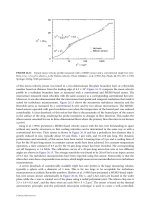
mechanism. Kwok et al. (2005) compared the continuum, slip-flow, and free molecular flow models for
Couette damping with data obtained by measuring the “ring down” of a tuning fork gyroscope fabricated
by Draper Laboratories. Figure 11.2 shows the measurements and theory confirming the functional
behavior of the damping as the pressure drops (Kn increases) and the unexpected accuracy of these rather
simple models. Although the trends are well-predicted, the absolute value of the Q-factor is still in error
by a factor of two, suggesting that more detailed computations are still of interest.
1
ᎏ
M
2
ᎏ
πγ
Quality factor (fluid) in drive axis
Knudsen number
Measurement (LCCC 701)
Continuum flow
Slip flow
Molecular flow
10
10
10
8
10
6
10
4
10
2
10
−2
10
0
10
0
10
2
10
4
10
6
FIGURE 11.2 (See color insert following page 10-34.) Theory and measurements of Couette damping in a tuning
fork gyro (Kwok et al. [2005]). Note that in the high Knudsen number limit, the free molecular approximation pre-
dicts the damping more closely, but that the slip-flow model, though totally inappropriate at this high Kn level, is not
too far from the experimental measurements.
© 2006 by Taylor & Francis Group, LLC
11.5 Squeeze-Film Damping
Squeeze-film damping arises when the gap size changes in an oscillatory manner squeezing the trapped
fluid (Figure 11.3). Fluid, usually air, is trapped between the vibrating proof mass and the substrate result-
ing in a squeeze film, which can significantly reduce the quality factor of the resonator. In some cases this
damping is desirable, but as with the case of Couette-flow damping, it is often parasitic, and the MEMS
designer tries to minimize its effects and maximize the resonant Q-factor of the device. Common methods
for alleviating squeeze-film effects are to fabricate breathing holes (“chimneys”) throughout the proof mass
which relieve the build up of pressure and to package the device at low pressure. Both of these solutions have
drawbacks. The introduction of vent holes reduces the vibrating mass, necessitating an even larger structure,
while the low-pressure packaging adds considerable complexity to the overall device development and
cost. Figure 11.4 illustrates a high-performance tuning fork gyroscope fabricated by Draper Laboratories.
11.5.1 Derivation of Governing Equations
The analysis of the squeeze-film damping is presented in the following section. The Reynolds equations
may be used as the starting point. However, a particularly elegant and complete solution was published
by Blech (1983) for the case of the continuum flow and was extended by Kwok et al. (2005) to the case of
slip-flow and flows films with vent holes. This analysis is summarized here.
Lubrication in MEMS 11-7
h(t ) = h
0
(1 +
sin
t )
FIGURE 11.3 Schematic of squeeze-film damping between parallel plates. As with Couette damping, for most prac-
tical embodiments of MEMS, the damping is quasi-steady.
FIGURE 11.4 Photograph of a typical microfabricated vibrating proof mass used in a high-performance tuning
fork gyroscope. (Reprinted with permission of M. Weinberg at Draper Laboratories.)
© 2006 by Taylor & Francis Group, LLC
11-8 MEMS: Introduction and Fundamentals
The Navier–Stokes equations are written for the case of a parallel plate vibrating sinusoidally in a pro-
scribed manner in the vertical direction. If we assume that the motion, subsequent pressure, and velocity
perturbations are small, a perturbation analysis yields the classical squeeze-film equation derived by
Blech, with an additional term due to the rarefaction:
ΨH
3
ϩ
6KH
2
ϭ
σ
(11.11)
where the variables have been non-dimensionalized, so that H represents the film gap, normalized by the
nominal film gap H ϭ h(x, y, t)/h
o
; Ψ is the pressure, normalized by ambient pressure Ψ ϭ P(x, y, t)/P
0
;
X and Y are the coordinates, normalized by the characteristic plate geometry X ϭ x/L
x
, Y ϭ y/L
y
; T is
time, normalized by the vibration frequency T ϭ
ω
t; and the squeeze number
σ
is defined as before:
σ
ϭ
(11.12)
Assuming small amplitude, harmonic forcing of the gap H ϭ 1 ϩ
ε
sin T, and a harmonic response of
the pressure, we can derive a pair of coupled equations describing the in-phase (Ψ
0
) and out-of-phase
(Ψ
1
) pressure distributions in the gap representing stiffness and damping coefficients, respectively:
ϩ Ψ
1
ϩ ϭ 0
ϩ
Ψ
0
ϭ 0 (11.13)
Note that these equations represent the standard conditions with the adoption of a modified squeeze
number,
σ
m
ϵ
σ
/(1 ϩ 6K). The solutions are achieved either by manual substitution of Fourier sine and
cosine series or by direct numerical solution. The results for rectangular plates with no vent holes are
shown in Figure 11.5.
σ
ᎏ
1 ϩ 6K
∂
2
Ψ
1
ᎏ
∂x
2
σ
ᎏ
1 ϩ 6K
σ
ᎏ
1 ϩ 6K
∂
2
Ψ
0
ᎏ
∂x
2
12
µω
L
2
x
ᎏ
P
0
h
2
0
∂(ΨH)
ᎏ
∂T
∂
Ψ
ᎏ
∂X
∂
ᎏ
∂X
∂Ψ
ᎏ
∂X
∂
ᎏ
∂X
0
0510 15 2520 30
Squeeze number
Non-dimensional forces
0.5
0.4
0.3
0.2
0.1
Damping force
Spring force
FIGURE 11.5 (See color insert following page 10-34.) Solutions to the squeeze-film equation for a rectangular plate.
The stiffness and damping coefficients are presented as functions of the modified squeeze number, which includes a
correction due to first-order rarefaction effects [Blech, 1983; Kwok et al., 2005].
© 2006 by Taylor & Francis Group, LLC
11.5.2 Effects of Vent Holes
The equations as previously derived are made more useful by extending them to account for the presence
of vent holes in the vibrating proof mass. In such cases the boundary condition at each vent hole is no
longer atmospheric pressure (Ψ
0
ϭ Ψ
1
ϭ 0), but rather an elevated pressure proscribed by the pressure
drop through the “chimney” which vents the squeeze film to the ambient. Kwok et al. (2005) demonstrate
that this can be incorporated into the previous model (in the limit of low squeeze number) by a modi-
fied boundary condition for the squeeze-film equations for Ψ
0
:
Ψ ϭ
΄
32
3
1 Ϫ
2
΅
΄
1 ϩ 8
1
΅
σ
(11.14)
12
4
This boundary condition has three components: a geometric component dependent on the plate thick-
ness t, length L
x
, hole size L
h
, and nominal gap size h
0
;ararefaction component (here based on the hole
size); and a time-dependent component — the squeeze number
σ
.Note that as the thickness of the plate
decreases and the chimney pressure drop falls, the boundary condition approaches zero. Similarly, as the
open area fraction of the plate increases (more venting), the boundary condition approaches that of the
ambient. This boundary condition can be applied at the chimney locations and can accurately simulate
the squeeze-film damping of perforated micromachined plates.
11.5.3 Reduced-Order Models for Complex Geometries
Most devices of practical interest have geometries that are too complex to enable full numerical simula-
tion of the kind described previously. Reduced-order models are of great value in such cases. Many such
models have been developed, including those based on acousto-electric models [Veijola et al., 1995]. In
the case of squeeze-film damping in the limit of low squeeze numbers, such models reduce to solution of
aresistor network that models the pressure drops associated with each segment of the squeeze film. This
is effectively a finite-element approach to the problem. Instead of modeling a large number of elements,
as is generally the case in a numerical solution, arelatively small number of discrete elements can be used,
if higher-order solutions can be employedtoconnect each element together. Kwok et al. (2005) demon-
strate this approach and model the damping associated with an inclined plate with vent holes. More com-
plex numerical solution techniques based on boundary integral techniques have also been presented
[Aluru and White, 1998; Kanapka and White, 1999] providing a good balance between solution fidelity
and required computing power.
11.6 Lubrication in Rotating Devices
Rotating MEMS devices bring a new level of complexity to MEMS fabrication and to the lubrication con-
siderations. As discussed in the introduction, many rotors and motors have been demonstrated with dry-
rubbing bearings, and the success of these devices is due to the low surface speeds of the rotors. However,
as the surface speed increases in order to get high power densities, the dry rubbing bearings are no longer
an option, and true lubrication systems need to be considered. An example of “Power-MEMS” develop-
ment is provided by a project initiated at the Massachusetts Institute of Te c hnology in 1995 to demon-
strate a fully functional microfabricated gas turbine engine [Epstein et al., 1997]. The baseline engine,
illustrated in Figure 11.6,consists of acentrifugal compressor, fuel injectors (hydrogen is the initial fuel,
although hydrocarbons are planned for later configurations), a combustor operating at 1600 K, and a
radial inflow turbine. The device is constructed from single crystal silicon and is fabricated by extensive
and complex fabrication of multiple silicon wafers that are fusion bonded in a stack to form the complete
L
h
ᎏ
L
x
λ
ᎏ
L
h
L
h
ᎏ
L
x
h
0
ᎏ
L
x
t
ᎏ
L
x
Lubrication in MEMS 11-9
© 2006 by Taylor & Francis Group, LLC
11-10 MEMS: Introduction and Fundamentals
device. An electrostatic induction generator may also be mounted on a shroud above the compressor to
produce electric power instead of thrust [Nagle and Lang, 1999]. The baseline MIT Microengine has at
its core a “stepped” rotor consisting of acompressor with an 8 mm diameter and a journal bearing and
turbine with a diameter of 6 mm. The rotor spins at 1.2 million r/min.
FIGURE 11.6 (Seecolor insert following page 10-34.) Schematic of the MIT Microengine, showing the air path
through the compressor, combustor, and turbine. Forward and aft thrust bearings located on the centerline hold the
rotor in axial equilibrium, while a journal bearing around the rotor periphery holds the rotor in radial equilibrium.
Forward thrust bearing
D
L
R
c
Main
turbine
air path
High pressure
plenum Low pressure
plenum
Aft thrust
bearing
Journal
bearing
Rotor
High pressure
plenum
Low pressure
plenum
Aft thrust
bearing
Forward thrust
bearing
Journal
bearing
Rotor
Main flow path
Axis of
rotation
FIGURE 11.7 Illustrating schematic and corresponding SEM of a typical microfabricated rotor, supported by axial
thrust bearings and a radial journal bearing.
© 2006 by Taylor & Francis Group, LLC
Key to the successful realization of such a device is the ability to spin a silicon rotor at high speed in a
controlled and sustained manner. The key to spinning a rotor at such high speeds is the demonstration
of efficient lubrication between the rotating and stationary structures. The lubrication system needs to be
simple enough to be fabricated but with sufficient performance and robustness to be of practical use in the
development program and in future devices. Figure 11.7 illustrates a microbearing rig that was fabricated
to develop this technology. The core of the rotating machinery has been implemented but without the
substantial complications of the thermal environment that the full engine brings. The rig consists of a
radial inflow turbine mounted on a rotor and embedded inside two thrust bearings that provide axial sup-
port. A journal bearing located around the disk periphery provides radial support for the disk as it rotates.
11.7 Constraints on MEMS Bearing Geometries
11.7.1 Device Aspect Ratio
Perhaps the most restrictive aspect of microbearing design is that MEMS devices are limited to rather shal-
low etches, resulting in devices with low aspect ratio. Even with the advent of deep reactive ion etchers
(DRIE) in which the ion etching cycle is interleaved with a polymer passivation step, the maximum prac-
tical etch depth that can be achieved while maintaining dimensional control is about 500 microns. Even
this has an etch time of about nine hours, which makes its adoption a very costly decision. In compari-
son, typical rotor dimensions are a few millimeters. The result is that microbearings are characterized by
very low aspect ratios (Length/Depth, or L/D). In the case of the MIT microturbine test rig, the journal
bearing is nominally 300 microns deep while the rotor is 4 mm in diameter, yielding an aspect ratio of
0.075. To put this in perspective, commonly available design charts [Wilcox, 1972] present data for val-
ues of L/D as low as 0.5 or perhaps 0.25. Prior to this work there was no data for lower L/D. The impli-
cations of the low aspect ratio bearings are that the task becomes supporting a disk rather than a shaft.
The low aspect ratio bearings do not have terrible performance by any standard. The key features of
the low L/D bearings are:
The load capacity is reduced compared to conventional designs. This is because the fluid leaking out of
the ends relieves any tendency for the bearing to build up a pressure distribution. For a given geom-
etry and speed, a short bearing supports a lower load per unit length than its longer counterpart.
The bearing acts as an incompressible bearing over a wide range of operation. Pressure rises, which
might lead to gas compressibility, are minimized by the flow leaking out of the short bearing.
Incompressible behavior (without the usual fluid cavitation that is commonly assumed in incom-
pressible liquid bearings) can be observed to relatively high speeds and eccentricities.
11.7.2 Minimum Etchable Clearance
It is reasonable to question why one could not fabricate a 300 micron long “shaft”, but with a much
smaller diameter, to greatly enhance the L/D. For example, a shaft with a diameter of 300 microns would
result in a reasonable value for L/D. This raises the second major constraint on bearing design by current
microfabrication technologies — that of the minimum etchable clearance.
In the current microengine manufacturing process, the bearing and rotor combination is defined by a
single deep and narrow etch, currently 300 microns deep and about 12 microns in width. No foreseeable
advance in fabrication technology will make it possible to significantly reduce the minimum etchable
clearance, and this has considerable implications for bearing design. In particular, if one were to fabricate
a bearing with a diameter of 300 microns in an attempt to improve the L/D ratio, the result would be a
bearing with a clearance to radius c/R of 12/300, or 0.04. For a fluid bearing, this is two orders of magni-
tude above conventional bearings and has several detrimental implications.
The most severe implication is the impact on the dynamic stability of the bearing. The non-dimensional
mass of the rotor depends on (c/R) raised to the fifth power [Piekos, 2000]. Bringing the bearing into the
center of the disk and raising the c/R by a factor of 10 results in a mass parameter increasing by a factor
of 10
5
. This increase in effective mass has severe implications for the stability of the bearing.
Lubrication in MEMS 11-11
© 2006 by Taylor & Francis Group, LLC
11-12 MEMS: Introduction and Fundamentals
These reasons and others not enumerated here make the implementation of an inner-radius bearing
less attractive. Therefore, the constraint of small L/D is unassailable as long as one requires that the
microdevice be fabricated in situ. If one were to imagine a change in the fabrication process such that the
rotor and bearing could be fabricated separately and subsequently assembled reliably, this situation would
be quite different. In such an event, the bearing gap is not constrained by the minimum etch dimension
of the fabrication process, and almost any “conventional” bearing geometry could be considered and
would probably be superior in performance to the bearings discussed here. Such fabrication could be
considered for a “one-off”device, but does not appear feasible for mass production, which relies on the
monolithic fabrication of the parts. Lastly, the risk of contamination during assembly — a common con-
cern for all precision-machined MEMS — effectively rules out piece-by-piece manufacture and assembly
and constrains the bearing geometry as described.
11.8 Thrust Bearings
Thrust bearings support any axial loads generated by rotating devices such as turbines, engines, or
motors. Current fabrication techniques require that the axis of rotation in MEMS devices lie normal to
the lithographic plane. This lends a significant advantage in the design and operation of thrust bearings
because the area available for the thrust bearing is relatively large as defined by lithography, while the
weight of the rotating elements will be typically small due to the cube-square law and the low thicknesses
of microfabricated parts. For these reasons, thrust bearings are one area of microlubrication where solu-
tions abound and problems are relatively easily dealt with.
Two thrust bearing options exist: (a) hydrostatic (externally-pressured) thrust bearings, in which the
fluid is fed from a high-pressure source to a lubrication film, and (b) hydrodynamic, where the support-
ing pressure is generated by a viscous pump fabricated on the surface of the thrust bearing itself (see
Figure 11.9). Hydrostatic bearings are easy to operate and relatively easy to fabricate. These have been suc-
cessfully demonstrated in the MIT Microengine program [Frechette et al., 2005; Liu et al., 2003]. The
thrust bearing in Figure 11.8 shows an scanning electron micrograph (SEM) of the fabricated device cut
though the middle to reveal the plenum, restrictor holes, and the bearing lubrication gap, which is
approximately 1 micron wide. Key to the successful operation of hydrostatic thrust bearings is the accurate
FIGURE 11.8 Close-up cutaway view of micro thrust bearing showing the pressure plenum (on top), the feed-holes,
and the bearing gap (faintly visible). (SEM reprinted with permission of Lin et al. [1999].)
© 2006 by Taylor & Francis Group, LLC
manufacture of the restrictor holes, maintenance of sharp edges at the restrictor exit, and careful control
of the dimension of the lubrication film. In an initial fabrication run, the restrictor holes were fabricated
2 microns larger than specified. While the bearing operated, its performance was well below its design
peak because of the off-design restrictor size. Current specifications of the fabrication protocols control
the restrictor size carefully, ensuring close to optimal operation.
Hydrodynamic or spiral groove bearings (SGBs), illustrated in Figure 11.9, were first analyzed in detail
forty years ago [Muijderman, 1966] but have not received much attention due to their low load capacity
compared to hydrostatic thrust bearings and due to complex manufacturing requirements.
SGBs operate by using the rotor motion against a series of spiral grooves etched in the bearing to vis-
cously pump fluid into the lubrication gap. This process creates a high-pressure cushion on which the rotor
can ride. The devices typically have relatively low load capacity, which has limited their use in macroscopic
applications. The load capacity becomes more than adequate at microscales due to favorable cube-square
Lubrication in MEMS 11-13
−
0.15
−
0.3
0.3
0
0.15
0.45
−
0.45
1.50E+06
1.30E+06
1.10E+06
9.00E+05
7.00E+05
5.00E+05
Eccentricity
High pressure plenum
(pumped up by spiral grooves)
Rotor
Stator
Axis of rotation
Inward-pumping
spiral grooves
FIGURE 11.9 Schematic of hydrodynamic thrust bearings and predicted performance (stiffness in N/m vs. axial
eccentricity) for a typical spiral groove thrust bearing for use in a high speed MEMS rotor.
© 2006 by Taylor & Francis Group, LLC
11-14 MEMS: Introduction and Fundamentals
scaling. Thus, they gain considerable advantage when compared with conventional hydrostatic thrust
bearings as the scale and Reynolds number decreases. In addition, the fabrication of the multitude of
shallow spiral features, which is an expensive task for a traditional SGB, is ideally suited for lithographic
fabrication technologies such as MEMS.
Figure 11.9 illustrates the bearing stiffness for a particular single-point design for the MIT microrotor
rotating at design speed (2.4 million r/min) and supported by matched forward and aft spiral groove bear-
ings. The stiffness at full speed is quite impressive and superior to comparable hydrostatic bearings, but
the SGB do suffer at lower speeds since the bearing stiffness is roughly proportional to rotational speed.
For this design, the lift-off speed (the speed at which the film can support the weight of the rotor and the
pressure distribution associated with the turbine flow) is only a few thousand r/min, and the dry rubbing
endured during startup will be minimal. SGBs also have the strong advantage that the two matched spi-
ral groove bearings, forward and aft, naturally balance each other with no supply pressures to maintain
or adjust, and the removal of the thrust bearing plena and restrictor holes considerably simplifies the
overall device fabrication. This simplification allows for the use of two fewer wafers in the wafer-bonded
stack, which is a considerable advantage from the perspective of manufacturing process cost and yield. A
hybrid bearing consisting of both hydrostatic and hydrodynamic bearings has been recently successfully
demonstrated [Wong et al., 2004] up to a speed of approximately 450,000 r/min.
11.9 Journal Bearings
Journal bearings, which are used to support radial loads in a rotating machine, have somewhat unusual
requirements in MEMS. These requirements derive from the extremely shallow structures that are cur-
rently fabricated. Rotating devices tend to be disk-shaped, and their corresponding journal bearings are
characterized by very low aspect ratios which are defined as the ratio of the bearing height to its radius.
In addition, the minimum etchable gap allowed by current fabrication techniques results in a paradoxically
large bearing clearance — a 10 micron gap over a 2 mm radius rotor, or a c/R of 1/200. This bearing clear-
ance is large in comparison to conventional journal bearings, which typically have c/R ratios that are
smaller by a factor of 10.
Journal bearings can operate in two distinct modes: hydrodynamic and hydrostatic. Ty pically any oper-
ating condition will contain aspects of both modes. These modes are discussed in the following sections.
11.9.1 Hydrodynamic Operation
Hydrodynamic operation occurs when the rotor is forced to operate at an eccentric position in the bear-
ing housing. As a result, a pressure distribution develops in the gap to balance the viscous stresses that
arise due to the rotor motion. This pressure distribution supports the rotor statically against the applied
force and dynamically to suppress random excursions of the rotor due to vibration, etc. Hydrodynamic
operation has the advantage of requiring no external supply of lubrication fluid. However, it has two dis-
tinct drawbacks: it requires a means to load the rotor to an eccentric position, and insufficient eccentric-
ity results in instability (the so-called “fractional speed whirl”) and likely failure. Both of these issues are
particularly difficult in the case of MEMS bearings.
11.9.1.1 Static Journal Bearing Behavior
Figure 11.10 shows the static behavior of a MEMS journal bearing. This figure presents the load capacity
ζ
and the accompanying attitude angle (the angle between the applied load and the eccentricity vector)
as functions of the bearing number and the operating eccentricity. The geometry considered here is for a
low-aspect ratio bearing (L/D ϭ 0.075) typical of a deep reactive ion etched rotor such as the MIT
microengine. The bearing number is defined as:
Λ ϭ
΄ ΅
2
(11.15)
R
ᎏ
c
6
µω
ᎏ
p
© 2006 by Taylor & Francis Group, LLC
where
µ
is the fluid viscosity,
ω
the rotation rate, p the ambient pressure, and R/c the ratio of the radius
to clearance. For a given bearing geometry, Λ can be interpreted as operating speed.
Several aspects of these results should be noted. The load capacity is quite small when compared with
bearings of higher L/D. This is because for very short bearings, the applied load simply squeezes the fluid
out of the bearing ends, and consequently it is difficult to develop any significant restoring force. The
same mechanism is responsible for the load lines being straight. Straight load lines indicate that little
Lubrication in MEMS 11-15
10
0
10
−1
10
−2
10
−3
10
−4
10
−5
10
−1
10
0
10
1
Λ
=
0.8
=
0.6
=
0.4
=
0.2
Λ
90
70
50
30
10
10
−1
10
0
10
1
0
φ (deg)
=
0.8
=
0.8
=
0.9
FIGURE 11.10 Static performance (eccentricity and attitude angle vs. bearing number) for a journal bearing with
L/D ϭ 0.075. Notice that the load lines are almost constant (linear), indicating the absence of compressibility effects.
This is also indicated by the attitude angle, which remains close to 90 degrees except at very high eccentricities [Piekos
and Breuer, 1998].
© 2006 by Taylor & Francis Group, LLC
11-16 MEMS: Introduction and Fundamentals
compressibility of the fluid is taking place, which usually results in a “saturation” of the load parameter at
higher values of the bearing number. Again, this is because any tendency to compress the gas is alleviated
by the fluid venting at the bearing edge. The behavior of the attitude angle, which maintains a high angle
(close to
π
/2) over a wide range of bearing numbers and eccentricities, illustrates this point. This value of the
attitude angle corresponds to the analytic behavior of aFull-Sommerfeld incompressible short bearing [Orr,
1999]. This value is a good approximation for such short bearings at low to moderate eccentricities when the
eccentricity remains below approximately 0.6. Below 0.6, compressibility finally becomes important. This
incompressible behavior is much more extensive than conventional gas bearings of higher aspect ratio and
has profound ramifications, particularly with respect to the dynamic properties of the system.
11.9.1.2 Journal Bearing Stability
The stability of a hydrodynamic journal bearing has long been recognized as troublesome and is foreshad-
owed by the static behavior shown in Figure 11.10. The high attitude angle suggests that the bearing spring
stiffness is dominated by cross stiffness as opposed to direct stiffness. Thus, any perturbation to the rotor
will result in its motion perpendicular to the applied force. If this reaction is not damped, the rotor will enter
a whirling motion. This is precisely what is observed, and gas bearings are notorious for their susceptibility
to fractional-speed whirl. The instability is suppressed by the generation of more damping and increased
direct stiffness, both of which are obtained by increasing the loading and the static eccentricity of the rotor.
Figure 11.11 shows a somewhat unusual presentation of the stability boundaries for a low-aspect ratio
MEMS journal bearing. The vertical axis shows the non-dimensional mass of the rotor M
ෆ
which is defined as:
M
ෆ
ϭ
΄ ΅
5
(11.16)
This is the “mass” which appears in the non-dimensionalized equations of motion for the rotor and it is
fixed for a given geometry. Close inspection of Figure 11.11 indicates that M
ෆ
does changes very slightly
with speed. This is because of the elastic expansion of the rotor due to centrifugal forces, the variation in
the ambient pressure at different speeds, and temperature effects on viscosity. The horizontal axis of
Figure 11.11 shows the bearing number, which can be interpreted as speed, for a fixed bearing geometry.
The contours on the graph represent the stability boundary at fixed eccentricity. Stable operation lies
above each line. For a fixed M
ෆ
at low bearing number (i.e., speed), a minimum eccentricity must be
c
ᎏ
R
mp
ᎏ
72L
µ
2
10
1
10
0
10
−1
10
−2
10
−1
10
0
M
Λ
=
0.925
= 0.900
= 0.850
= 0.800
FIGURE 11.11 Stability boundaries for a typical microbearing plotted vs. bearing number (speed for a fixed geom-
etry). The dotted line represents an operating line for a microbearing which has almost constant M
ෆ
(varying only due
to centrifugal expansion of the rotor at high speeds [Piekos, 2000]).
© 2006 by Taylor & Francis Group, LLC
obtained to ensure stability. As the speed increases, this minimum eccentricity remains almost constant
(the lines are horizontal) until a particular speed at which the lines break upward, and the minimum
eccentricity required for stability starts to drop as indicated by Figure 11.10, as Λ increases, the load
required to maintain a fixed eccentricity increases linearly due to the stiffening of the hydrodynamic bear-
ing. The key feature of this chart is that the minimum eccentricities are very high and suggest that stable
operation requires running very close to the wall. This is troublesome. The high eccentricities are driven
by high values of the mass parameter M
ෆ
which is due to the relatively high value of the clearance-to-
radius ratio (c/R) and the short length L. The low aspect ratio (L/D) also contributes to high minimum
eccentricities. At high speeds, the problem becomes less severe, because the high speed allows the bearing
to generate sufficient direct stiffness. Even at these points, the eccentricity is very high and might not be
manageable in practical operation.
Orr (1999) has demonstrated on a scaled-up experimental rig that matches the microengine geometry
that stable high-eccentricity operation is possible for extended periods of time. His experiments achieved
46,000 r/min which, when translated to the equivalent speed at the microscale, correspond to approxi-
mately 1.6 million r/min. In order to accomplish this high eccentricity operation, he noted that the rotor
system must (a) have very good axial thrust bearings to control axial and tipping modes of the rotor sys-
tem, and (b) be well-balanced. A rotor with imbalance of more than a few percent could not be started
from rest. Piekos (2000) also explored the tolerance of the microbearing system to imbalance and found
that it was surprisingly robust to imbalance of several percent. His computations were achieved assuming
that the rotor was at full speed and then carefully subjected to imbalance. In practice, the imbalance will
exist at rest, and the rotor is stable at full speed but unable to accelerate to that point. This “operating line”
issue is discussed in more detail by Savoulides et al. (2001) who explored several options for accelerating
microbearings from rest under both hydrodynamic and hydrostatic modes of operation.
Figure 11.12 illustrates a convenient summary of the trade-offs for design of a hydrodynamic MEMS
bearing. This figure presents the variation of the low-speed minimum eccentricity asymptote, or worst-
case eccentricity, as a function of the mass parameter M
ෆ
and other geometric factors (L/D, clearance, c,
Lubrication in MEMS 11-17
0.95
0.9
0.85
0.8
0.75
0.7
0.65
0.6
0.55
0.5
Worst-case eccentricity
10
−4
10
−3
10
−2
10
−1
10
0
10
1
10
2
M
Stable
2R, L, (1/2)C
d = 0.8 µm
2R, L, C
d = 0.8 µm
R, L, (1/2)C
d = 0.9 µm
2R, L, (1/2)C
d = 1.4 µm
R, 2L, C
d = 1.6 µm
R, 2L, 2C
d = 1.5 µm
2R, 2L, 2C
d = 1.3 µm
R, L, C
d = 0.9 µm
L/D = 0.0375
L/D = 0.075
L/D = 0.15
Unstable
FIGURE 11.12 Tradeoff chart for microbearing design. For a given length-to-diameter (L/D) and a given
M
—
, the worst-case (i.e., low-speed) eccentricity is shown for a variety of geometric perturbations. In general, lower
eccentricities are preferred. (Reprinted with permission from Piekos [2000].)
© 2006 by Taylor & Francis Group, LLC
11-18 MEMS: Introduction and Fundamentals
e
tc.). Notice that the worst-case eccentricity improves as the L/D increases and the M
ෆ
dec
reases. However, the
p
hysical running distance from the wall is actually increased slightly by running at a higher eccentricity
with a larger bearing gap. In all cases, the stable eccentricity is alarmingly high, and other alternatives
need to be sought for simpler stable operation.
11.9.2 Advanced Journal Bearing Designs
One prospect for further improvement in the journal bearing performance is the incorporation of wave
bearings [Dimofte, 1995] as illustrated in Figure 11.13. These bearing geometries suppress the sub-
synchronous whirl due to the excitation of multi-synchronous pressure perturbations imposed by the
bearing geometry. The geometric complexity of the wave bearing is no problem for lithographic manu-
facturing processes that are used for MEMS. This alleviates many of the reservations and costs that might
inhibit their adoption. Because the MEMS constraint is the minimum gap dimension, the wave bearing
in a MEMS machine can be implemented only by selectively enlarging the bearing gap. Piekos (2000) ana-
lyzed the performance of the wave bearing for the microengine geometry and found (Figure 11.14) that
while the load capacity is diminished, the stability is enhanced and the load required to maintain stable
operation (i.e., to achieve the minimum stable eccentricity) is reduced considerably with the introduc-
tion of a wave geometry. In microbearings the load capacity is usually sufficient, and the wave bearing is
attractive as a stabilizing mechanism.
Rotor imbalance, which is increasingly becoming a first-order issue, can only be contained with excess
load capacity, and this tradeoff is not clear. The adoption and testing of wave bearing geometries are
scheduled to be explored as part of our development program.
11.9.3 Side Pressurization
Due to the small mass of the rotor in a MEMS device, any eccentricity required to enable stable hydro-
dynamic operation must be applied using some other means. Typically, this requires the use of a pressure
distribution introduced around the circumference of the bearing. This pressure distribution loads the
bearing preferentially to one side. Such a scheme is illustrated in Figure 11.15 for the MIT Microengine.
FIGURE 11.13 (Seecolor insert following page 10-34.) Geometry of a wave bearing, with the clearance greatly exag-
gerated for clarity [Piekos, 2000].
© 2006 by Taylor & Francis Group, LLC
The aft side of the rotor is divided into two plena isolated by seals. Each plenum can be separately pres-
surized. The pressure in each plenum forces an axial flow through the journal bearing to the forward side
(which is assumed to be at a uniform pressure), and thus establishes two differing pressure distributions
on the high- and low-pressure sides of the rotor. As a result, the axial flow through the bearing generates
a hydrostatic stiffness mechanism and an associated hydrostatic critical frequency. These results are dis-
cussed in the following section.
11.9.4 Hydrostatic Operation
Although hydrodynamically lubricated bearings with low aspect ratio are predicted to operate success-
fully and have been demonstrated on a scaled-up level [Orr, 1999], there are a number of issues that make
Lubrication in MEMS 11-19
10
−1
10
−2
10
−3
ζ
Stable
Circular
S
a
m
p
l
e
o
p
e
r
a
t
i
n
g
l
i
n
e
w
= 0.2
w
= 0.4
w
= 0.6
Unstable
20 40 60 80 10
0
% speed
FIGURE 11.14 Effect of wave bearing amplitude on journal bearing stability as a function of rotor speed. The
dotted line shows a typical operating line for a microengine [Piekos, 2000].
Main
turbine
air path
High side
pressure
Low side
pressure
Rotor
FIGURE 11.15 Schematic of the pressure-loading scheme used in the microengine to provide a side load to the rotor
during hydrodynamic operation. The side load is developed by applying a differential pressure to the two plena
located on the aft side of the rotor.
© 2006 by Taylor & Francis Group, LLC
11-20 MEMS: Introduction and Fundamentals
them undesirable in a practical MEMS rotor system. The primary difficulty is that, in order to satisfy the
requirements of sub-synchronous stability, the rotor needs to operate at very high eccentricity (made
unavoidable due to the low aspect ratio of the journal). For a MEMS device this means operating 1–2
microns from the wall. This is hard to control, particularly with the limited available instrumentation for
MEMS devices. An alternative mode of operation is to use a hydrostatic lubrication system. In this mode,
fluid is forced from a high-pressure source through a series of restrictors, all of which impart a fixed
resistance. The fluid then flows through the lubrication passage (the bearing gap). If the rotor moves to
one side, the restrictor and lubrication film act as a pressure divider such that the pressure in the lubri-
cation film rises, forcing the rotor back towards the center of the bearing. The advantages of using hydro-
static lubrication in MEMS devices are that:
The rotor tends to operate near the center of the housing, and small clearances are avoided. This is safer,
more tolerant of any motion induced by rotor imbalance, and results in lower viscous resistance.
Because the hydrostatic system is a zero-eccentricity based system, no position information about the
rotor is needed. This greatly simplifies instrumentation requirements.
There are significant disadvantages to a hydrostatic system, including:
Pressurized air needs to be supplied to the bearing. This requires supply channels, which complicate
the fabrication process and come with a system cost: the high-pressure air must come from some-
where. In a turbomachinery application, bleed air from the compressor could be used.
Since the bearing gaps are relatively large due to minimum etchable dimensions previously discussed,
the mass flow through hydrostatic systems can be substantial and might be impractical in anything
but demonstration experiments.
Fabrication constraints make the manufacture of effective flow restrictors very difficult. Flow restric-
tors need to have very well controlled dimensions, sharp edges, and other specific geometric features.
Only the simplest restrictors can be implemented without undue cost and effort, severely limiting
the hydrostatic design.
Orr (1999) demonstrated a novel method for achieving hydrostatic lubrication for journal bearings with
low aspect ratio. The mechanism relies on the small pressure differences that exist between the forward and
aft sides of the rotor. The mechanism also relies on the flow resistance to the pressure differences being
small enough such that an axial flow will ensue for a short bearing of the kind seen in MEMS devices.
As the flow enters the bearing channel, boundary layers develop along the wall eventually merging to
form the fully developed lubrication film. This boundary layer development (Figure 11.16) acts as an
inherent restrictor. If the rotor moves off the centerline and disturbs the axisymmetric symmetry of the flow,
a restoring force is generated. This source of hydrostatic stiffness supports the bearing at zero eccentricity
Boundary
layers
Rotor
W
FIGURE 11.16 Schematic illustrating the origin of the axial-through-flow hydrostatic mechanism.
© 2006 by Taylor & Francis Group, LLC
and is effective even when the rotor is not moving. The conventional inherent restriction of the flow entering
the lubrication channel also enhances the stiffness. The stiffness coupled with the rotor mass defines a nat-
ural frequency which was measured by Orr (1999). The presence of this frequency led to the discovery of
the axial-through-flow mechanism. Simple theory [Orr, 1999] was also able to predict the frequency in a
scaled-up experimental facility with reasonable accuracy (Figure 11.17).
There is a severe gap in our ability to accurately predict and account for all the hydrostatic lubrication
phenomena in a real microrotor. Experiments conducted at the microscale [Frechette et al., 2005] demon-
strate successful operation at high speeds (1.4 million r/min) despite theoretical predictions of failure.
Experimental measurements suggest that the natural frequency is higher than predicted by the simple axial-
through-flow theory of Piekos (2000) and that the damping is sufficient to operate at critical speed ratios
(rotor frequency, scaled by the natural frequency of the hydrostatic system) greater than 10. Conventional
analysis [Orr, 1999] suggests that the instability occurs at critical speed ratios of 2. This discrepancy suggests
that the real bearing exhibits significantly higher damping than is accounted for by the theory, perhaps
Lubrication in MEMS 11-21
Natural frequency (Hz)
60
50
40
30
20
10
0
Natural frequency (Hz)
60
50
40
30
20
10
0
0 1 2 3 4 5
Axial pressure difference (psig)
Axial pressure difference (psig)
0 0.5 1 1.5 2 2.5 3 3.5 4 4.
5
Experiment
Model
Experiment
Modified model
FIGURE 11.17 Prediction and measurement of natural frequency associated with axial-through-flow in a low-aspect
ratio microbearing. The left-hand frame shows the measurements (from a 26:1 scaled-up experimental rig) along with the
theoretical predictions based on the assumed geometry. The right-hand frame shows the same measurements compared
with the same model but using slightly modified geometric parameters. [Orr, 1999].
© 2006 by Taylor & Francis Group, LLC
deriving from the turbine which drives the rotor or some other source of fluid damping not yet considered.
The resolution of these discrepancies need more attention and will be aided greatly by improved models and
more detailed measurements of the microrotor in operation.
11.10 Fabrication Issues
A key challenge to the successful operation of a high-speed microbearing is the accurate fabrication of
bearing geometries. Two aspects of this challenge need to be considered: the need to hold design toler-
ances in any given fabrication process, and the ability to manufacture multiple devices with good unifor-
mity in a single fabrication run.
The issue of achieving design tolerances is a matter of process maturity. The attention paid to the
maintenance of tight tolerances and small details is the hallmark of a well-established fabrication process.
The microengine process is very complex and continually advances the state of the art in micromachin-
ing complexity. Almost any fabrication run that results in a freely rotating turbine should be considered
a manufacturing triumph. From the standpoint of the success of the system, we must have much more
stringent manufacturing requirements. The bearing designs are sensitive to critical dimensions such as
the bearing-rotor gap and the size of restrictor holes for hydrostatic injectors. The failure to hold these
dimensions within a specified tolerance can make the difference between a device that operates with a
lubricated film and one that grinds the rotor and stator surface until failure. The very first version of the
microbearing rig ran in this mode with occasional demonstrations of lubricated operation. Subsequent
designs and builds have paid attention to dimensional accuracy, and the fabrication protocols are quite
mature so that this precision is ensured from one build to the next.
11.10.1 Cross-Wafer Uniformity
Typically, multiple microengines are fabricated in parallel on a single silicon wafer. In addition to the
accurate manufacture of critical dimensions on a single microengine die, the importance of manufactur-
ing uniformity from one die to the next on a single wafer is vital. Manufacturing unity is a major obstacle
to device yield. It is very common for a given process to exhibit cross-wafer variations. For example, a
shallow plasma etch into a silicon substrate might show a variance of as much as 10% from one side of
the wafer to the other because of variations in the plasma that are intrinsic to the fabrication tool. All fab-
rication processes will exhibit such variations, and any microfabrication process needs to identify and
accommodate these variations. Should the variations be unacceptably large, either the fabrication tool
needs to be improved, or a different processing path needs to be considered. This need is a common driver
throughout both the MEMS and microelectronics industry. This industry also desires greater process uni-
formity as feature size diminishes and processing moves to larger and larger wafers.
As previously discussed, there are several critical etches that need to be controlled to a high degree of
precision for microbearing design. The difficulty in maintaining cross-wafer uniformity results in some
operational devices on the wafer (typically from the center of the wafer, where the process was initially
honed to precision). Many devices from the wafer edge are out of specification and will not operate sat-
isfactorily. At this stage, most of the uniformity issues have been addressed. However, two items are still
troublesome. The deep reactive ion etcher being a relatively new tool exhibits a fairly significant variation
in etch rate between the center and edge of a wafer. This variation results in a gradient in etch depth that
is particularly severe on devices lying on the wafer periphery (3 microns variation across a 4 mm rotor
wheel). This gradient contributes to a mass imbalance of as much as 25% of the bearing gap, rendering the
bearing inoperable at high speed. The imbalance force increases with the square of the rotational speed.
The second continuing difficulty is that of front-to-back mask alignment during fabrication. It is
common during the fabrication process for a single silicon wafer to be patterned on both the front and
back surfaces. For example, the rotor has the turbine blades patterned from one side and the bearing gap
patterned from the other side. Any slight misalignment between the lithography on the front and back sur-
faces of the wafer will result in an offset of front and back features which, as with the etch-depth gradient,
11-22 MEMS: Introduction and Fundamentals
© 2006 by Taylor & Francis Group, LLC
leads to a rotor imbalance. Currently, mask alignment of critical features, primarily the rotor blades and
the bearing gap, must be maintained to within 0.5 microns or better in order to ensure operable rotors
from every die on the wafer. This is an extremely tight, but achievable, tolerance, and work continues to
improve the alignment even further and to improve process design to minimize imbalance.
11.10.2 Deep Etch Uniformity
The last issue for fabrication precision is that of deep etch uniformity. Any high-speed bearing depends
critically on the straightness and parallelism of the sidewalls that constitute the bearing and rotor sur-
faces. This is particularly true for hydrodynamic operation at high eccentricity. In the drive to generate
deep trenches so that the bearing aspect ratio is minimized, the quality of the bearing etch is often com-
promised. These two issues, the etch depth and the etch quality, constantly pull against each other. Their
relative advantages need to be weighed against each other in any final design.
Figure 11.18 shows typical non-uniform etch profiles for DRIE. This figure illustrates two common phe-
nomena: etch bow, where the trench widens in the middle, and etch taper, where the trench widens (usu-
ally) at the bottom. The effects of these non-uniformities have been analyzed computationally [Piekos and
Breuer, 2002]. As one might expect, the static performance of the bearing (load capacity) is degraded by
the blow-out, particularly in the case of the tapered bearing where fluid pressure cannot accumulate in the
gap but rather leaks out the enlarged end. The bowed bearing, because of its concave curvature, tends to
hold the pressure more successfully, and the loss in load capacity is typically less severe. As mentioned ear-
lier, load capacity is less of an issue in microbearings, and it is the effect on hydrodynamic stability that is
of most interest. Figure 11.19 summarizes the effects of bow and taper on hydrodynamic operation. This
figure shows the minimum stable eccentricity as a function of bearing number (i.e., speed, for a fixed bear-
ing geometry) for different levels of bow and taper. The effects of taper are most severe, and considerable
effort has been placed in the fabrication process design to minimize bearing taper.
11.10.3 Material Properties
One of the key benefits realized at the microscale is the improvement in strength-related material prop-
erties. This is particularly true in silicon-based MEMS where the baseline structural material is single-
crystal silicon, which can be fabricated to have very good mechanical properties. The strength of brittle
materials is controlled primarily by flaws and to some extent by grain boundaries, both of which become
smaller or non-existent in a single-crystal material with surfaces defined by microfabrication processes.
The device size becomes comparable with the flaw distribution such that the incidence of “super-strong”
Lubrication in MEMS 11-23
FIGURE 11.18 SEMs of bearing etches, illustrating typical manufacturing non-uniformities. The left-hand SEM
shows an etch with a bow in the center. The right-hand SEM shows an etch with a taper. (SEM reprinted with
permission of A. Ayon.)
© 2006 by Taylor & Francis Group, LLC
11-24 MEMS: Introduction and Fundamentals
devices increases in microscale systems. Silicon is a light material with a density (2330kg/m
3
) lower than
that of aluminum (2700 kg/m
3
). The strength-to-weight ratio of silicon micromachined structures is
unparalleled, which is a key for high-speed rotating machinery. Despite its high specific strength silicon
is a very brittle material. For a high speed rotating system, such as a turbine, this can be problematic since
an impact or touchdown at any appreciable speed is likely to result in a catastrophic failure rather than
an elastic rebound or more benign plastic deformation. Figure 11.20 shows a photograph of a microtur-
bine rotor that crashed during a high-speed test run. The importance of robust bearings is emphasized
because the material is extremely unforgiving.
11.11 Tribology and Wear
When lubrication fails, tribology and wear become important as the focus shifts from the prevention of
contact to the mitigation of its effects. Tr ibology has been a subject of technical and industrial importance
1
0.95
0.9
0.85
0.8
ε
min
ε
min
10
−1
10
0
10
1
Λ
10
−1
10
0
10
1
Λ
1
0.95
0.9
0.85
0.8
0%
17%
25%
33%
∆c/c
FIGURE 11.19 Degradation of hydrodynamic stability due to bow (left frame) and taper (right frame), as
indicated by the minimum eccentricity required for hydrodynamic stability at a given bearing number (speed) [Piekos
and Breuer, 2002].
© 2006 by Taylor & Francis Group, LLC
since the industrial revolution, and a certain level of accomplishment was achieved that allows the design
and operation of complex machinery in difficult environments. With the advent of microengineering and
the development of the atomic force microscope, the field has defined a new set of problems and has wit-
nessed a rebirth of focus on the micro- and nano-scale processes associated with friction and wear. This
chapter does not address the progress in micro- and nano-tribology, however, a few general comments
are made that are valuable in practical MEMS devices.
11.11.1 Stiction
A common problem associated with the failure of MEMS devices is that of stiction in which two surfaces
touch and stick together due to the high surface energies. The problem is exacerbated by the use of wet-
etching during fabrication and by the relatively smooth surfaces (and thus high contact areas) associated
with MEMS materials. Many lubricants have been used to mitigate the problem. Self-assembling mono-
layers (SAMs), such as perfluoro-decyl-trichlorosilane, coat the surface with a monolayer of a long mol-
ecule that adheres to the surface at one end and is hydrophobic at the other end thus preventing stiction.
Other lubricants are also under investigation such as Fomblin-Zdol, which is used in the hard-disk indus-
try to protect the disk surface during head crashes and can be vapor-deposited during manufacture.
Other remedies include the intentional design of textured surfaces, or standoffs, to prevent large areas
coming into direct contact.
11.11.2 The Tribology of Silicon
Since most MEMS devices are silicon-based, the tribology of silicon has received considerable attention
in the past several years. Silicon is not a very desirable bearing material [Gardos 2001] and exhibits high
wear rates, high coefficients of friction, and poor stiction characteristics. Surface treatments (e.g., silicon
carbide, and fluorocarbon (Teflon™-like) materials) and appropriate design have improved matters con-
siderably. Most MEMS have not yet been designed with significant surface motions that require either
supporting lubrication films or protective coatings. This is likely to change as fabrication processes enable
more complex devices with higher power-densities and more challenging lubrication and wear require-
ments. The lifetime and reliability requirements of MEMS are becoming more severe because devices are
being developed for space, medical, and national defense applications. All of these applications have
Lubrication in MEMS 11-25
FIGURE 11.20 Photograph of the remains of a silicon rotor after experiencing a high-speed crash. The instant frac-
ture of the rotor (largely along crystallographic planes) is visible.
© 2006 by Taylor & Francis Group, LLC
11-26 MEMS: Introduction and Fundamentals
unique and stringent requirements for predicting lifetime, wear, and failure, and so this oft-neglected cor-
ner of the industry will receive the attention it deserves.
11.12 Conclusions
In this chapter, we have focused on some of the key issues that face the design, manufacture, and opera-
tion of microdevices that need to operate with minimal friction or wear. Many of the issues in Couette
and squeeze-film lubrication have been successfully addressed. Fundamental surface models (such as gas
accommodation coefficients) are still unknown, and reliable prediction methods are just becoming avail-
able. Stiction issues remain problematic although they are managed in an engineering manner. Increased
understanding of surface science is needed to solve this problem.
Rotating MEMS devices need much more development before they can be reliably manufactured and
used. Even with dramatic advances in lubricant and surface treatment technologies, high-speed operation
will likely require gas bearings which have always offered high-speed, low wear operation with the atten-
dant cost of a narrow and treacherous window of stable operation. Many of the commonly held assump-
tions and design rules that have guided previous fluid film bearings in conventional machinery have been
revisited due to the consequences of scaling and the current limitations in microfabrication technology.
Future research needs to focus attention in many areas. On the manufacturing side, the single largest
obstacle to trouble-free production of gas bearings for high-speed rotors and shafts is the issue of preci-
sion microfabrication. Macroscopic systems, with typical scale of 1 meter, need precision manufacturing
in places with sub-millimeter tolerances. Microdevices with typical dimensions of 1 mm will need toler-
ances of 1 micron or less. The ability to manufacture with such precision will require much improved
understanding of micromachining technologies such as etching and deposition so that cross-device and
cross-wafer uniformities can be improved.
At the level of lubrication technologies, the new parameter regimes that are exposed by microfabri-
cated systems (very low aspect ratios, relatively large clearances, insignificant inertial properties, etc.)
need to be further explored and understood. Despite the low Reynolds numbers, inertial losses are criti-
cally important for hydrostatic lubrication mechanisms and need to be better understood and predicted.
Similarly, the coupled fluid-structure interactions at high eccentricities and the interactions between
hydrodynamic and hydrostatic mechanisms need to be more fully explored. Fundamental issues of fluid
and solid physics need to be addressed as the scale continues to shrink. Gas surface interactions, momen-
tum and energy accommodation phenomena, and the effects of surface contamination (whether deliber-
ate or accidental) need to be rigorously studied so that the macroscopic behavior can be predicted with
some certainty. These issues will become more important as manufacturing scales decrease further and
as continuum assumptions become more problematic.
Acknowledgments
I am indebted to my several friends and collaborators over the years with whom I have been fortunate to
work in this exciting area. In particular, the contributions of Errol Arkilic, Stu Jacobson, Fred Ehrich, Alan
Epstein, Luc Frechette, Peter Kwok, C C. Lin, D.J. Orr, Ed Piekos, Nick Savoulides, Marc Weinberg, and
C W. Wong are gratefully acknowledged. Some of the contents of this chapter are drawn from a similar
paper presented at a NIST-sponsored workshop and published by Kluwer Press [Hsu, 2001].
References
Aluru, N.R., and White, J. (1998) “A Fast Integral Equation Technique for Analysis of Microflow Sensors
Based on Drag Force Calculations,” International Conference on Modeling and Simulation of
Microsystems, Semiconductors, Sensors and Actuators pp. 283–6, April, Santa Clara, CA.
Arkilic, E.B., Schmidt, M.A., and Breuer, K.S. (1997) “Gaseous Slip Flow in Long Microchannels,”
J. MicroElectroMech. Syst. 6(2), pp. 167–78.
© 2006 by Taylor & Francis Group, LLC
Arkilic, E., and Breuer, K.S. (1993) “Gaseous Flow in Small Channels,” AIAA 93-3270, AIAA Shear Flow
Conference, July, Orlando, FL.
Bart, S.F., Lorber, T.A., Howe, R.T., Lang, J.H., and Schlecht, M.F. (1988) “Design Considerations for
Micromachined Electric Actuators,” Sensor. Actuator., vol. 14, pp. 269–92.
Beskok, A., and Karniadakis, G.E. (1994) “Simulation of Heat and Momentum Transfer in Complex
Micro-Geometries,” J. Thermophys. Heat Transf. 8(4), pp. 647–55.
Blech, J.J. (1983) “On Isothermal Squeeze Films,” J. Lubr. Technol., vol. 105, pp. 615–20.
Breuer, K.S., Arkilic, E.B., and Schmidt, M.A. (2001) “Slip Flow and Tangential Momentum
Accommodation in Silicon Micromachined Channels,” J. Fluid Mech. 437, pp. 29–44.
Burgdorfer, A. (1959) “The Influence of the Molecular Mean Free Path on the Performance of
Hydrodynamics Gas Lubricated Bearing,” J. Basic Eng., vol. 81, pp. 94–9.
Cai, C P., Boyd, I.D., Fan, J., and Candler, G.V. (2000) “Direct Simulation Methods for Low-Speed
Microchannel Flows,” J. Thermophys. Heat Transf., vol. 14, pp. 368–78.
Dimofte, F. (1995) “Wave Journal Bearing with Compressible Lubricant. Part 1: The Wave Bearing
Concept and a Comparison to the Plain Circular Bearing,” Tribol. Trans. vol. 38, pp. 153–60.
Epstein, A.H., Senturia, S.D., Al-Midani, O., Anathasuresh, G., Ayon, A., Breuer, K., Chen, K S., Ehrich,
F.E., Esteve, E., Frechette, L., Gauba, G., Ghodssi, R., Groshenry, C., Jacobson, S., Kerrebrock, J.L.,
Lang, J.H., Lin, C C., London, A., Lopata, J., Mehra, A., Mur Miranda, J.O., Nagle, S., Orr, D.J.,
Piekos, E.S., Schmidt, M.A., Shirley, G., Spearing, S.M., Tan, C.S., Tzeng, Y S., and Waitz, I.A.
(1997) “Micro-Heat Engines, Gas Turbines and Rocket Engines - the MIT Microengine Project,”
AIAA Paper 97-1773 Snowmass, CO, June.
Fréchette, L.G., Jacobson, S.A., Breuer, K.S., Ehrich, F.F., Ghodssi, R., Khanna, R., Wei Wong, C., Zhang, X.,
Schmidt, M.A., and Epstein, A.H. (2005) “High-Speed Microfabricated Silicon Turbomachinery
and Fluid Film Bearings,” J. MicroElectroMech. Syst. 14(1), pp. 141–52.
Gardos, M. (2002) Nanotribology, S. Hsu, ed., Kluwer Academic Press, New York.
Hamrock, B.J. (1984) Fundam. Fluid Film Lubr., McGraw-Hill, New York.
Hsu, S., ed. (2001) Nanotribology, Kluwer Press, New York.
Kwok, P., Weinberg, M., and Breuer, K.S. (2005) “Fluid Effects in Vibrating Micro-Machined Structures”
J. MicroElectroMech. Syst. (in press)
Lin, C C., Ghodssi, R., Ayon, A.A., Chen, D-Z., Jacobson, S., Breuer, K.S., Epstein, A.H., and Schmidt, M.A.
(1999) “Fabrication and Characterization of Micro Turbine/Bearing Rig,” Proceedings, MEMS99,
January, IEEE, Orlando, FL.
Liu, L.X., Teo, C.J., Epstein, A.H., and Spakovszky, Z.S. (2003) “Hydrostatic Gas Journal Bearings for
Micro-Turbomachinery,” Proceedings of ASME-DEC’03, September, Chicago.
Mehregany, M., Senturia, S.D., and Lang, J.H. (1992) “Measurement of Wear in Polysilicon Micromotors,”
IEEE Trans. Electron Devices, vol. 39, pp. 1136–43.
Muijderman, E.A. Spiral Groove Bearings, Springer Verlag, New York.
Nagle, S.F., and Lang, J.H. (1999) “A Micro-Scale Electric-Induction Machine for a Micro Gas-
Turbine Generator;” Presented at the 27th Meeting of the Electrostatics Society of America, June,
Boston, MA.
Orr, D.J. (1999) Macro-Scale Investigation of High Speed Gas Bearings for MEMS Devices, Ph.D. thesis,
Department of Aeronautics and Astronautics, MIT Cambridge, MA.
Piekos, E.S. (2000) Numerical Simulations of Gas-Lubricated Journal Bearings for Microfabricated
Machines, Ph.D. thesis, Department of Aeronautics and Astronautics, MIT Cambridge, MA.
Piekos, E.S., and Breuer, K.S. (1999) “Pseudo-Spectral Orbit Simulation of Non-Ideal Gas-Lubricated
Journal Bearings for Microfabricated Turbomachines,” J. Tribol., vol. 121, pp. 604–9.
Piekos, E.S., and Breuer, K.S. (2002) “Manufacturing Effects in microfabricated gas bearings: axially vary-
ing clearance” J. Tribol. 124, pp. 815–21.
Reynolds, O. (1886) “On the Theory of Lubrication and Its Application to Mr. Beauchamp Tower’s
Experiments, Including an Experimental Determination of the Viscosity of Olive Oil,” Royal
Society, Phil. Trans., pt. 1.
Lubrication in MEMS 11-27
© 2006 by Taylor & Francis Group, LLC