The MEMS Handbook MEMS Applications (2nd Ed) - M. Gad el Hak Episode 1 Part 5 potx
Bạn đang xem bản rút gọn của tài liệu. Xem và tải ngay bản đầy đủ của tài liệu tại đây (2.5 MB, 30 trang )
4.4.1.8 Buckling
When a short column is loaded in compression, the average compressive stress is calculated by simply
dividing the load by the cross-sectional area as in Equation 4.1. However, when the column is long and
slender, the situation is complicated by the possibility of static instability, also known as lateral buckling.
When loaded below the buckling threshold, acolumn under a compressive load will get shorter while
remaining essentially straight. After the buckling threshold is exceeded, the column deflects normally to
the axis of the column and the stress increases rapidly. These stresses can cause failure by rupture.
The phenomenon of buckling is much different than that of bending. A beam will begin to bend as
soon as any moment (bending load) is present. In contrast, acolumn will not exhibit any lateral deflec-
tion until the critical or buckling load is reached. Above the critical load, additional loading causes large
increases in lateral deflection. Because of the tensile properties of polysilicon, it is possible to design a col-
umn to buckle without exceeding the yield strength. If yield does not occur, the column will return to its
original straight position after the load is removed. If designed appropriately, a buckling column can be
used as an out-of-plane flexure [Garcia 1998].
Buckling is a complex nonlinear problem and predicting the shape of the buckled structure is beyond
the scope of this text. It is, however, covered in several references including Timoshenko and Gere (1961),
Brush and Almroth (1975), Hutchinson and Koiter (1970), and Fang and Wickert (1994). However, the
equation for predicting the onset of buckling is relatively straightforward. For a column with one end
fixed and the other free to move in any direction (i.e., a cantilever), the critical load to cause buckling is:
F
CR
ϭ (4.36)
It is important to remember that the critical load for buckling cannot exceed the maximum force sup-
ported by the material. In other words, if the load needed to cause buckling is larger than the load needed
to exceed the compressive strength, the column will fail by rupture before buckling.
4.4.1.9 Hinges and Hubs
A different type of rigid-body-mode machine is a vertical axis hinge. These hinges are used in surface
micromachining to create three-dimensional structures out of a two-dimensional surface micromachin-
ing process. In the surface micromachining process, hinges are constructed by stapling one layer of poly-
silicon over another layer of polysilicon with a sacrificial layer between them. A cross section of a simple
hinge is illustrated in Figure 4.16. A more complex hinge is shown in Figure 4.17.Hinges have some
π
2
EI
ᎏ
4L
2
4-18 MEMS: Applications
Sacrificial oxide
Polysilicon
Substrate
FIGURE 4.16 Cross section of a polysilicon mirror hinge. The top figure shows the device before release, the mid-
dle drawing is after release, and the bottom depicts the actuated device.
© 2006 by Taylor & Francis Group, LLC
advantages over flexible joints. One advantage is that no stress is transmitted to the hinged part so greater
angles of rotation are possible. Also, the performance of hinged structures is not influenced by the thick-
ness of the material and deformation of the machine is not required. The limitations of hinged structures
are that the sacrificial layers must be thick enough for the hinge pin to rotate and at least two released lay-
ers of material are required. Hinges are also susceptible to problems with friction, wear, and the associ-
ated reliability problems. The same limitations and advantages are true for structures that rotate parallel
to the plane of the substrate such as gears and wheels. A cross section of a simple hub and gear is shown
in Figure 4.18 and a complex hub structure is shown in Figure 4.4.
4.4.1.10 Actuators
There are several different actuation techniques for surface micromachine mechanisms. Actuators for all
types of MEMS devices are covered in Chapter 5, but the most common actuator types for surface micro-
machines — electrostatic and thermal — are also covered here. Electrostatic actuators harness the attrac-
tive Coulomb force between charged bodies. For a constant voltage between two parallel plates, the energy
stored between the plates is given by:
W ϭ (4.37)
where
ε
0
is the dielectric constant of free space (8.854 ϫ10
Ϫ12
F/m),
ε
r
is the relative dielectric constant,
for air it is 1.0, A is the area, V is the voltage, and y is the distance. The force between the plates is attractive
and given by:
F ϭ Ϫ ϭ (4.38)
ε
0
ε
r
AV
2
ᎏ
y
2
dW
ᎏ
dy
ε
0
ε
r
AV
2
ᎏ
2y
Surface Micromachined Devices 4-19
FIGURE 4.17 Hinged polysilicon micromirror fabricated in the Sandia National Laboratories SUMMiT™ process.
(Photograph courtesy of Sandia National Laboratories.)
Substrate
FIGURE 4.18 Cross section of a simple hub and gear fabricated in a two level surface micromachining process.
© 2006 by Taylor & Francis Group, LLC
Note that this force is dependent on 1/y
2
. Therefore, the Coulomb force is very strong at small gaps, but
drops off rapidly as the gap increases. If the plates are not fully engaged, as in Figure 4.19, there will be
tangential as well as normal forces. The equation for the tangential motion is obtained by modifying
Equation 4.37 by substituting the area term, A, with the product of the lateral dimensions z and x:
W ϭ ϭ (4.39)
The derivative of energy with respect to position is force.
F ϭ ϭ (4.40)
Note that this force is not dependent on the lateral position x. Comb-drive actuators utilize these tan-
gential forces with banks of comb fingers. The surface micromachined comb-drive in Figure 4.20 typically
operates at voltages of 90 V and has output forces of around 10 µN. Comb-drives can operate at speeds
up to 10 s of kHz and consume only the power necessary to charge and discharge their capacitive plates.
ε
0
ε
r
zV
2
ᎏ
2y
dW
ᎏ
dx
ε
0
ε
r
xzV
2
ᎏ
2y
ε
0
ε
r
AV
2
ᎏ
2y
4-20 MEMS: Applications
y
x
z
Tangential forces
Area
Normal forces
FIGURE 4.19 Illustration of normal and tangential forces in an electrostatic actuator.
FIGURE 4.20 Electrostatic comb-drive actuator fabricated in the SUMMiT V
TM
process at Sandia National
Laboratories.
© 2006 by Taylor & Francis Group, LLC
Because the output force of an electrostatic comb-drive is proportional to the square of the applied voltage,
these devices are often operated at higher voltages than most analog and digital integrated circuits. This
has complicated their implementation into systems. It should be noted that Equations 4.37 through 4.40
are for electrostatic actuators connected to a power supply and in constant voltage mode.
Example
The plate in Figure 4.19 is 50 µm long, 6 µm thick, and 3 µmwide. It has a neighboring electrode that
is 1 µmaway.If80 V are applied between the electrode and its identical neighbor and fringing is ignored,
what are the forces in the normal and tangential directions if the combs are aligned in the width dimen-
sion and overlap by 40 µm and 10 µm in the length dimension? How much does the force change in both
directions if the distance is reduced to 0.1 µm? If there are 30 electrodes at 80 V interlaced with 31 elec-
trodes at 0 V as in Figure 4.20 with a separation of 1 µm between the electrodes what is the net tangential
force? Assume that
ε
r
ϭ 1.0.
Parallel plate electrostatic forces for the 40 µm of overlap case are:
F
normal
ϭϭ ϭ14 ϫ 10
Ϫ6
N
and for the 10 µm case:
F
normal
ϭϭ ϭ4.4 ϫ 10
Ϫ6
N
For the tangential force, the lateral dimension, x, is not included in Equation 4.40 so both calculations
yield the same result.
F
tangential
ϭϭ ϭ ϭ1.7 ϫ 10
Ϫ7
N
The reader should note that the parallel plate force is much higher than tangential force. If the separation
is reduced to 0.1 µm, then the normal force is increased by a factor of 100 to 440 µN and the tangential
force is increased by a factor of 10 to 1.7 µN. For 30 energized electrodes and 31 non-energized electrodes,
the tangential force is multiplied by the number of energized electrodes and then doubled to account for
both faces of the electrode:
F
30 fingers
ϭ 170 nN ϫ30 ϫ 2 ϭ 10 µN
Note that the parallel plate force of one electrode engaged 40 µm is still higher than the tangential force
of 30 electrodes. However, the tangential force comb-drive has a force that is independent of position,
while the parallel plate case falls off rapidly with distance. However, the high forces at small separations
makes parallel plate actuators useful for electrical contact switches.
Thermal actuators have higher forces (hundreds of µN up to a few mN) and operate at lower voltages
(1 Vto 15 V) than electrostatic actuators. They operate by passing current through a thermally isolated
actuator. The actuator increases in temperature through resistive heating and expands, thus moving the
load. One type of thermal actuator has two beams that expand different amounts relative to each other
[Guckel et al, 1992; Comtois, 1998]. These pseudo bimorph or differential actuators use a wide beam and
a narrow beam that are electrically resistors in series and mechanically flexures in parallel. Because the
narrow beam has a higher resistance than the wide beam, it expands more and bends the actuator in an
arc around the anchors.
Another type of thermal actuator uses two beams that are at a shallow angle. Bent beam thermal actu-
ators generally have strokes of between 5 µm and 50 µm [Que et al., 2001; Cragun and Howell, 1999].
Unlike the pseudo bimorph devices, they move in a straight line instead of an arc. Like the pseudo bimorph
actuators, they have an output force that falls off quickly with displacement. Both types of thermal actua-
tors are shown in Figure 4.21.
8.854 ϫ 10
Ϫ12
F/m ϫ 1 ϫ 40 ϫ 10
Ϫ6
m ϫ (80V)
2
ᎏᎏᎏᎏᎏ
2 ϫ 1 ϫ 10
Ϫ6
m
ε
0
ε
r
zV
2
ᎏ
2y
dW
ᎏ
dx
8.854 ϫ 10
Ϫ
12
F/m ϫ 1 ϫ10 ϫ 10
Ϫ
6
m ϫ 6 ϫ 10
Ϫ
6
m ϫ (80 V)
2
ᎏᎏᎏᎏᎏᎏᎏ
(1 ϫ 10
Ϫ6
m)
2
ε
0
ε
r
xzV
2
ᎏ
y
2
8.854 ϫ10
Ϫ
12
F/m ϫ 1 ϫ 40 ϫ 10
Ϫ
6
m ϫ 6 ϫ 10
Ϫ
6
m ϫ (80 V)
2
ᎏᎏᎏᎏᎏᎏᎏ
(1 ϫ 10
Ϫ6
m)
2
ε
0
ε
r
xzV
2
ᎏ
y
2
Surface Micromachined Devices 4-21
© 2006 by Taylor & Francis Group, LLC
4.5 Packaging
This section covers only aspects of packaging that are especially relevant to surface micromachines. One
of the challenges of packaging surface micromachines is that the packaging is application specific and
varies greatly between different types of devices. This is one reason that packaging tends to be the most
expensive part of surface micromachined devices. Therefore it is very important that designers of surface
micromachines understand packaging and collaborate with engineers specializing in packaging while
designing their device. Some of the main purposes of packages for surface micromachines include elec-
trical and mechanical connections to the next assembly and protection from the environment.
The mechanical attachment between a die and a package can be achieved in several different ways. The
main criteria for choosing a die-attach method include: the temperature used during the die-attach
process; the amount of stress the die-attach process induces on the die; the electrical and thermal prop-
erties of the die-attach; the preparation of the die for the die-attach process; and the amount of out-
gassing that is emitted by the die-attach. Die-attach methods that do not outgas include silver-filled
glasses and eutectics (gold–silicon). Both of these induce a large amount of stress onto the die as well as
requiring temperatures of around 400°C. Epoxy-based die-attaches use much lower temperatures (up to
150°C) and induce lower stress on the die than eutectics or silver-filled glasses. The low stress means that
they can be used for larger die. However, depending on the type of epoxy, they do outgas water and cor-
rosive chemicals such as ammonia. As an alternative, flip-chip processes combine the process of die-
attach and electrical interconnection by mounting the die upside-down on solder balls. A note of caution:
surface micromachines are strongly influenced by coatings and contamination or removal of these coat-
ings, which can happen during temperature cycling, is detrimental to the micromachine.
Electrical interconnect to surface micromachines is typically accomplished by wire bonding.
Wirebonders use a combination of heat, force, and ultrasonic energy to weld a wire (normally aluminum
or gold) to a bondpad on the surface micromachined die. The other end of the wire is welded to the pack-
age. Although, wirebonds in high volume production have been done on less than 50µmcenters, for low
volume applications it is easier if the bondpads are fairly large. Metal coated bond pads that are 125 µm
or larger on a side with 250 µm center-to-center spacing allow reworking of the wire bonds and for non-
automated wire bonding equipment to be used. These numbers are on the conservative side but could be
followed in the absence of process specific information. Figure 4.22 shows an Analog Devices ADXL50
surface micromachined accelerometer with its wirebonds and epoxy die-attach.
4-22 MEMS: Applications
Cold
Cold
Electrical current
Hot
Hot
Electrical current
Absolute
actuator
Differential
actuator
Motion
Motion
Cold
FIGURE 4.21 Drawings of absolute and differential thermal actuators.
© 2006 by Taylor & Francis Group, LLC
While electrical and mechanical connections to surface micromachines are similar to other types of
micromachines and integrated circuits, the mechanical protection aspects of the packaging can be quite
different. The package must protect the surface micromachine from handling by people or machines,
from particles and dust that might mechanically interfere with the device, and from water vapor that can
induce stiction. Packages for some resonant devices must maintain a vacuum and all packages must keep
out dust and soot in the air. However, sensor packages must allow the MEMS device to interact with its
environment. Because surface micromachines are very delicate and fragile after release, even a careful
packaging process can damage a released die. Therefore, one of the trends in packaging is to encapsulate
and mechanically protect the devices as early as possible in the manufacturing process. Henry Guckel at
the University of Wisconsin was one of the first developers of an integrated encapsulation technique
[Guckel, 1991]. In this design, the surface micromachine was covered by an additional layer of structural
material during the fabrication process. This last structural layer completely encapsulates the surface
micromachine with the exception of a hole used to permit removal of the sacrificial layer by the release
etchant. After the release etch, the hole is sealed with materials ranging from LPCVD films, to sputtered
films, to solders. There is a good summary of this and other sealing techniques in Hsu (2004).
Another method of encapsulating the device is to use wafer bonding. In this technique a cap wafer is
bonded to the device wafer forming a protective cover. One common method involves anodic bonding of
aglass cover wafer over the released surface micromachines. A second involves the use of intermediate
layers such as glass frit, silicon gold eutectic, and aluminum. The wafer bonding techniques are more
independent of the fabrication process than the wafer level deposition processes. Because of the lack of
stiction forces between the cap and the substrate and because film stresses in the cap are not a problem,
bonded caps can be used for larger devices than deposited caps. A package formed by Corning 7740 glass
(pyrex) bonded to a surface micromachine is shown in Figure 4.23.
Conventional packaging such as ceramic or metal packages also protect surface micromachines from
the environment. In this case, the package provides electrical and mechanical interconnections to the next
assembly as well as mechanical protection. These types of packages tend to be more expensive than plas-
tic packages, which can be used if encapsulation is done on the wafer level. These packages are typically
sealed using either a welding operation that keeps the surface micromachine at room temperature or a
Surface Micromachined Devices 4-23
FIGURE 4.22 Analog Devices accelerometer after the package lid has been removed. The epoxy die-attach and wire
bonds are clearly visible. This device had its package lid removed at Sandia National Laboratories. (Photograph cour-
tesy of Jon Custer of Sandia National Laboratories.)
© 2006 by Taylor & Francis Group, LLC
belt sealing operation that elevates the temperature of the entire assembly to several hundred degrees
Centigrade.
4.6 Applications
The applications section of this chapter will present some surface micromachined mechanisms and dis-
cuss them with regard to some of the mechanical concepts discussed earlier. The chapter concludes with
some design rules and lessons learned in the design of surface micromachined devices.
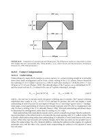
4.6.1 Countermeshing Gear Discriminator
One example of a surface micromachined mechanism is the countermeshing gear discriminator that was
invented by Polosky et al. (1998). This device has two large wheels with coded gear teeth. Counter-rotation
pawls restrain each wheel so that it can rotate counterclockwise and is prevented from rotating clockwise.
The wheels have three levels of teeth that are designed so they will interfere if the wheels are rotated in
the incorrect sequence. Only the correct sequence of drive signals will allow the wheels to rotate and open
an optical shutter. If mechanical interference occurs, the mechanism is immobilized in the counterclock-
wise direction by the interfering gear teeth and by the counter-rotation pawls in the clockwise direction.
A drawing of the device and a close-up of the teeth are shown in Figures 4.24 and 4.25,respectively. The
wheels have three levels of intermeshing gear teeth that will allow only one sequence of rotations out of
the more than the 16 million that are possible. Because the gear teeth on one level are not intended to
interfere with gear teeth on another level and because the actuators must remain meshed with the code
wheels, the vertical displacement of the code wheels must be restricted. This was accomplished with dim-
ples on the underside of the coded wheels that limited the vertical displacement to 0.5 µm. War page of
the large 1.9-mm-diameter coded wheels is reduced by adding ribs with an additional layer of polysilicon.
The large coded wheels are prevented from rotating backward by the counter-rotation pawls. These
devices must be compliant in one direction and capable of preventing rotation in the other direction. The
next example discusses counter-rotation pawls.
4-24 MEMS: Applications
FIGURE 4.23 A surface micromachine encapsulated by a piece of glass. Comb-drives can be seen through the right
side of the mechanically machined cap. This process can be accomplished either on a die or wafer basis. (Photograph
courtesy of A. Oliver, Sandia National Laboratories).
© 2006 by Taylor & Francis Group, LLC
Example
Figure 4.26 shows a counter-rotation pawl. The spring is 180 µm long from the anchor to a stop
(labeled as l) and 20µm long from the stop to the end of the flexible portion (denoted as a), with a width of
2 µm and a thickness of 3 µm. The Young’s modulus is 155 GPa. Assume that the tooth on the free end of
Surface Micromachined Devices 4-25
FIGURE 4.24 The countermeshing gear discriminator. The two code wheels are the large gears with five spokes in the
center of the drawing; the counter-rotation pawls are connected to the comb-drives; and the long beams in the upper
right and lower left portion of the photograph. (Drawing courtesy of M.A. Polosky, Sandia National Laboratories.)
FIGURE 4.25 Teeth in the countermeshing gear discriminator. The gear tooth on the left is on the top level of polysil-
icon and the gear tooth on the right is on the bottom layer. If the gears do not tilt or warp, the teeth should pass with-
out interfering with each other. (Photograph courtesy of Sandia National Laboratories.)
© 2006 by Taylor & Francis Group, LLC
4-26 MEMS: Applications
the beam does not affect the stiffness and that the width of the stop is negligible. Find the spring constant
of the pawl if the gear is rotated in the counterclockwise direction. Comment on the spring constant if
the gear is rotated in the clockwise direction.
In the counterclockwise direction, the spring constant k is:
k ϭ ϭ 0.12 N/m
using a length l ϩ a of 200 µm. In the clockwise direction, it is tempting to redefine the spring length as
20 µm. The resulting spring constant is 116 N/m. Unfortunately, this is an oversimplification because the
beam will deform around the stop. The exact equation is in Timoshenko’s Strength of Materials
[Timoshenko, 1958] and in Equation 4.41:
k ϭ
1
ϩ
(4.41)
This equation results in a spring constant of 15 N/m, which is still very stiff but not as stiff as the results
of the oversimplified calculation.
4.6.2 Microengine
One important element of many polysilicon mechanism designs is the microengine.This device, described
by Garcia and Sniegowski (1995) and shown in Figures 4.27 to 4.29, uses an electrostatic comb-drive
a
2
l
ᎏ
4EI
a
3
ᎏ
3EI
Ew
3
t
ᎏ
4L
3
a
1
FIGURE 4.26 Example of a simple counter-rotation pawl. The stop is assumed to have a width of 0.
© 2006 by Taylor & Francis Group, LLC
connected to a pinion gear by a slider-crank mechanism with a second comb-drive to move the pinion
past the top and bottom dead center. Two comb-drives are necessary because the torque on a pinion pro-
duced by a single actuator has a dependence on angle and is given by the following equation:
Torque ϭ F
0
r|sin(
θ
)| (4.42)
Surface Micromachined Devices 4-27
X
Y
FIGURE 4.27 Mechanical representation of a microengine.
FIGURE 4.28 Drawing of a microengine. The actuator measures 2.2 mm ϫ 2.2 mm and produces approximately
55 pN-m of torque.
© 2006 by Taylor & Francis Group, LLC
where F
0
is the force of the comb-drive,
θ
describes the angle between hub of the output gear and the link-
age, and r is the distance between the hub and the linkage. The torque produced by the “Y” actuator has a
similar dependence on angle. The inertia of the rotating pinion gear is not great enoughtorotate the gear
past the top and bottom dead center. One important feature of this device is that the conversion from linear
motion to rotary motion requires the beams between the actuator and the driven gear to bend. The bending
is permitted by a polysilicon linkage that is 40 µm in length and 1.5µm in width with a thickness of 2.5 µm.
Example
The comb-drive labeled “X” in Figure 4.27 has an actuator arm that must bend 17µm in the lateral
direction as the gear rotates from 0° to 90°. The gear is connected to the comb-drive via a 50-µm-wide
beam that is 500 µm long in series with a thin flexible link that is 1.5 µmwide and 45 µm long. The thin
link is connected to the comb-drive actuator and both beams have a Young’s modulus of 155 GPa. Given
that both beams are 2.5 µm thick, approximately how much force does it take to bend to the flexible link-
age to rotate the gear from q ϭ 0to q ϭ 90° if friction and surface forces are neglected? A drawing of this
linkage is shown in Figure 4.29.
Assume that each segment is a cantilever beam spring that has one end fixed while the other end is
undergoing a small deflection. For each beam:
y
max
ϭ
(4.43)
and
k ϭ ϭ
(4.44)
Recall that for rectangular cross sections:
I ϭ
(4.14)
Using substitution, the equivalent spring constant for the long beam is:
k ϭϭ ϭ97 Nրm
155 GPa ϫ (2.5 µm)(50 µm)
3
ᎏᎏᎏ
4 ϫ (500 µm)
3
Etw
3
ᎏ
4L
3
tw
3
ᎏ
12
3EI
ᎏ
L
3
P
ᎏ
y
MAX
PL
3
ᎏ
3EI
4-28 MEMS: Applications
Linka
g
e connection
Flexible links
Hub
FIGURE 4.29 Detail of Figure 4.28 showing the thin linkages that connect the comb-drives to the gear.
© 2006 by Taylor & Francis Group, LLC
and for the short beam:
k ϭϭ
ϭ
3.6 N/m
By Equation 4.35, the equivalent spring rate is:
ϭ ϩ ϭϩ ϭ
3.5 N/m
We can employ some simple trigonometry and calculus to determine the needed deflection of the flex-
ure. From the section on cantilever beam springs:
y ϭ
(3Lx
2
Ϫ x
3
)
(4.21)
Because the majority of the bending occurs in the thin flexible link the desired slope of the flexible link
at its end is:
ϭ ϭ
(6Lx Ϫ 3x
2
) (4.45)
For the case of the small flexible link, I is equal to:
I ϭϭ ϭ7 ϫ10
Ϫ25
m
4
Because x ϭ L ϭ 45 µm, P can be calculated as:
P ϭ
ϫ 6 ϫ 155 GPa ϫ 7.0 ϫ 10
Ϫ25
m
4
ϫ
ϭ 3.4 µN
4.6.3 Micro-Flex Mirror
The Micro-Flex mirror is a device that deforms out of plane through buckling [Garcia, 1998]. It can be
built in any surface micromachining process that has at least one level of released structural material. This
device can be configured as a mirror, an optical shutter, a valve, or any structure that requires a plate or
beam to move out of the plane of fabrication. A scanning electron microscope (SEM) photograph of the
device is shown in Figure 4.30. The mirror consists of a long flexible beam connected to a plate that in
turn is connected to two anchors via two additional flexible beams. The device operates by buckling.
When a force is placed on the long flexible beam in the direction of the anchors, the structure is placed
under a compressive force. When the force exceeds the critical value described by Equation 4.36, the
structure buckles. Because the long flexible beam is larger in the direction parallel to the plane of the sub-
strate than it is in the direction away from the substrate, it preferentially buckles out of the plane of the sub-
strate. Also, because the plate and the two anchor beams are wider than the long flexible beam, the majority
of the bending occurs in the long flexible beam and not in the plate or the anchor beams. The next example
discusses the buckling criteria.
Example
Determine how much axial force is needed for a micromachined polysilicon mirror to buckle given the
following dimensions. The main beam is 300 µm long, 4 µm wide, and 1 µm thick with a Young’s modu-
lus of 155 GPa. Assume that the beam can be simplified to be a cantilever. Neglect the buckling of the
anchors and the mirror.
1
ᎏᎏᎏᎏ
6 ϫ (45 µm)
2
Ϫ 3 ϫ (45 µm)
2
17 µm
ᎏ
545 µm
2.5 µm ϫ (1.5 µm)
3
ᎏᎏᎏ
12
tw
3
ᎏ
12
P
ᎏ
6EI
17 µm
ᎏ
545 µm
dy
ᎏ
dx
P
ᎏ
6EI
1
ᎏ
3.6 Nրm
1
ᎏ
97 Nրm
1
ᎏ
k
2
1
ᎏ
k
1
1
ᎏ
k
eq
155 GPa ϫ (2.5 µm)(1.5 µm)
3
ᎏᎏᎏ
4 ϫ (45 µm)
3
Etw
3
ᎏ
4L
3
Surface Micromachined Devices 4-29
© 2006 by Taylor & Francis Group, LLC
The moment of inertia for this situation is:
I ϭϭ ϭ3.3 ϫ 10
Ϫ25
m
4
From the mechanics of materials section we know that the minimum force to buckle the beam is:
F
cr
ϭ (4.36)
Substituting this into the equation for force and using 155 GPa as the value of Young’s modulus we have
the following:
F
cr
ϭ ϭ 1.4 µN
As the example shows, it is necessary to have a great deal of force in order to buckle the flexible mir-
ror. In the original paper by Garcia (1998), atransmission (shown in Figure 4.31) was used to increase
the force on the mirror. The transmission traded displacement for force to ensure that the mirror buck-
led. The amount of deflection after buckling is a nonlinear dynamics problem and beyond the scope of
this book. For those readers interested in the subject, good references include the work of Timoshenko
and Gere (1961), Brush and Almroth (1975), and Hutchinson and Koiter (1970). Fang and Wickert
(1994) have examined the subject for micromachined beams. One interesting aspect of buckling is that it
is impossible to determine if the beam will initially buckle toward or away from the substrate. If the beam
buckles away from the substrate, it will continue to deflect away from the substrate. If it initially buckles
toward the substrate, it will contact the substrate and further compression of the beam will result in the
structure buckling away from the substrate.
Example
For the mechanism shown in Figure 4.31, how much mechanical force is made available by the trans-
mission if the microengine output gear has a diameter of 50 µm and an applied torque of 50 pN-m, the
large spoked wheel has a diameter of 1600 µm, and the pin joint that links the spoked wheel to the mirror
π
2
ϫ 155 ϫ 10
9
N/m
2
ϫ 3.3 ϫ 10
Ϫ25
m
4
ᎏᎏᎏᎏᎏ
4 ϫ (300 ϫ 10
Ϫ6
m)
2
π
2
EI
ᎏ
4L
2
4 ϫ 10
Ϫ6
m ϫ (1 ϫ 10
Ϫ6
m)
3
ᎏᎏᎏ
12
wt
3
ᎏ
12
4-30 MEMS: Applications
FIGURE 4.30 A flexible pop-up mirror that operates via buckling. In this photograph the buckling is out of the
plane of the substrate. (Photograph courtesy of E.J. Garcia of Sandia National Laboratories.) A further description of
this device can be found in Garcia, E.J. (1998) “Micro-Flex Mirror and Instability Actuation Technique,” in Proc. 1998
IEEE Conf. on Micro Electro Mechanical Systems (MEMS ’98), pp. 470–474.
© 2006 by Taylor & Francis Group, LLC
is 100 µm from the hub? Determine the maximum force in the direction of the mirror at the pin joint,
neglecting friction, if there is a gap of 0.5 µm between the linkage and the pin joint.
The torque available at the pin joint is:
torque ϭ 50 pNm ϫ ϭ 1600 pNm
and the radial force at the pin joint is:
F
radial
ϭ ϭ 16 µN
If there was no gap in the pin joint the force at the pin joint would be given by:
F
mirror
ϭ
(4.47)
where
θ
is the angle between a line connecting the pin joint and the mirror and a line connecting the pin
joint and the hub. However, there is a gap or slop in the pin joint. Sin(
θ
) is given by:
sin(
θ
) ϭ ϭ 0.005
If the motion of the spoked wheel is assumed to be in a straight line instead of an arc. The resulting
output force is:
F
mirror
ϭ ϭ ϭ 3.2 mN
This example is taken after Garcia (1998), who included a more detailed derivation that accounts for the
rotation of a “c”-shaped linkage.
16 µN
ᎏ
0.005
F
radial
ᎏ
sin(
θ
)
0.5 µm
ᎏ
100 µm
F
radial
ᎏ
sin(
θ
)
1600 pNm
ᎏᎏ
100 µm
1600 µm
ᎏ
50 µm
Surface Micromachined Devices 4-31
Hinge joint
Guides
Hub
Pin joint
C Shaped likage
Pinion of
micro-engine
FIGURE 4.31 A flexible mirror in its initial state and a large gear with spokes. The spoked wheel acts as a transmis-
sion and is used to gain enough mechanical advantage to buckle the beam. Two important features are the hinge joint
and guides which convert the off-axis motion of the “c-shaped” linkage to motion that is aligned with the mirror. The
c-shaped linkage was designed to avoid fabricating the linkage above the rotating joint and thus causing fabrication
problems. (Photograph courtesy of E.J. Garcia, Sandia National Laboratories.)
© 2006 by Taylor & Francis Group, LLC
Example
The large forces produced by the linkage system in the previous example are important for overcom-
ing stiction. Calculate the adhesive force due to van der Waals forces for a 150 µm ϫ150 µm mirror if the
surface of the mirror is separated from the substrate by 8 nm and the surface under the mirror is silicon
dioxide with a Hamaker constant of 5 ϫ10
Ϫ
20
J. Compare this result to a mirror that has four 2 µmby
2 µm dimples that are also 8 nm from the substrate.
From Equation 4.8:
ϭϪ ϭϪ ϭ5180
For a mirror that is 150 µm ϫ 150 µm the force required is:
F ϭ ϫ area ϭ 5180 ϫ (150 ϫ 10
Ϫ6
m)
2
ϭ 120 µN
For a mirror with dimples:
F ϭ ϫ area ϭ 5180 ϫ 4 ϫ (2 µm)
2
ϭ 83 nN
Note that the adhesive forces due to stiction are much smaller when dimples are used.
4.7 Failure Mechanisms in MEMS
For most practioners, the field of MEMS and surface micromachines has a steep learning curve. Often the
learning occurs through repeated iterations of the same design, but this can be very time consuming and
expensive because the time between design completion and testing is usually measured in months and the
price per fabrication run is many thousands of dollars. This section describes some failures in surface
micromachined mechanisms. The hope is that the reader will gain a deeper appreciation for the com-
plexities of surface micromachined mechanism design and learn about some of the pitfalls.
4.7.1 Vertical Play and Mechanical Interference in Out-of-Plane Structures
Surface micromachined parts typically have a thickness that is very small in relationship to their width or
breadth. In the out-of-plane direction, the thickness is limited to a few micrometers due to the limited
deposition rates of deposition systems and the stresses in the deposited films. In the plane of the sub-
strate, structures can be millimeters across. These factors typically lead to surface micromachined struc-
tures that have a very small aspect ratio as well as stiffness issues in the out-of-plane direction due to the
limited thickness of the parts. The result is that designers of surface micromachines need to design struc-
tures in three dimensions and account for potential movements out of the plane of the substrate. A
potential problem occurs when two gears fabricated in the same structural layer of polysilicon fail to
mesh because one or both of the gears are tilted. Another is when structures moving above or below
another structure mechanically interfere with each other when it was intended for them to not touch each
other. Both of these instances will be examined separately.
An example of the out-of-plane movement of gears is illustrated in Figure 4.32.In this instance, the
driven gear in the top of the figure has been wedged underneath the large load gear at the bottom of the
photograph. The way to prevent this situation is to understand the forces that create the out-of-plane motion
and to reduce or restrain them. One way of reducing the relative vertical motion of meshed gears is to
increase the ratio of the radius of the hub to the radius of the gear. Mathematically, the maximum dis-
placement of the outside edge of a gear from its position parallel to the plane of the substrate is:
Y
max
ϭ R ϫ Y/X (4.48)
N
ᎏ
m
2
dΓ
ᎏ
dx
N
ᎏ
m
2
dΓ
ᎏ
dx
N
ᎏ
m
2
5 ϫ10
Ϫ20
Nm
ᎏᎏᎏ
6
π
ϫ (8 ϫ10
Ϫ9
m)
3
A
ᎏ
6
π
x
3
dΓ
ᎏ
dx
4-32 MEMS: Applications
© 2006 by Taylor & Francis Group, LLC
where the radius of the hub is X, the vertical play in the hub is Y, the radius of the gear is R, and the max-
imum vertical displacement is Y
max
.The increase in hub diameter, while it can increase the amount of adhe-
sive forces in the hub, does not increase the amount of frictional forces in the rotating or sliding structure.
The vertical displacement of a gear can also be limited by contact with the substrate.One way of lim-
iting this is to place dimples on the underside of the gear. Dimples are commercially available in several
surface micromachining processes including the MUMPS process offered by MEMSCAP and the
SUMMiT™ process offered by Sandia National Laboratories. The dimples are generally spaced well apart
from each other, depending on the stiffness of the gear and the prevalence of stiction. They typically
occupy less than 1% of the surface area.
Another method of restraining the vertical motion of surface micromachined parts involves the use of
clips above or below the gear or other moving structure as shown in Figure 4.33. Generally three or four
clips are used, which is enoughtorestrain the moving structure while limiting the increase in the amount
of frictional forces on the gear. Dimples on the bottom of the clips can further reduce the amount of play.
Of course, all of these techniques can be combined to reduce vertical play.
Another type of reliability problem is the tendency for mechanical systems to increase their level of
entropy and become disconnected or disengaged. The following example illustrates the point. A pin and
socket joint was the connection between an actuator and an optical shutter. A cross section of the joint is
shown in Figure 4.34.Unfortunately, the side walls of the socket are slightly sloped and the arm is not
restrained in the vertical direction. In Figure 4.35, the force between a pin and the optical shutter was
relieved, not by the horizontal movement of the shutter, but by the vertical movement of the pin, which
slid up the sloped side walls of the shutter and out of the socket. The proper way to design this joint would
be to use an additional layer of polysilicon below the shuttertorestrain the linkage in the vertical direc-
tion. An alternative approach would be to attach the linkage to the shutter and make the linkage compli-
ant to compensate for the rotation of the shutter.
Unintended vertical motion of surface micromachined parts can be exacerbated by structures that are
soft in the vertical direction. Figure 4.36 shows a beam with a dimple that is caught on a gear. There
should have been no interaction between the two elements because the fabricated dimple should have
cleared the gear by 0.5 µm. Unfortunately in this case, neither the gear nor the spring is adequately elec-
trically grounded, which may have caused some electrostatic attractive force between the two. Stiction
Surface Micromachined Devices 4-33
FIGURE 4.32 (See color insert following page 2-12.) The gear teeth of the small gear are wedged underneath the
teeth of the large diameter gear. In this case, gear misalignment is about 2.5 mm in the vertical direction.
© 2006 by Taylor & Francis Group, LLC
may also have contributed to the proximity of the two parts. The spring constant of this beam in the ver-
tical direction is much too soft at 1.5 ϫ 10
Ϫ3
N/m. The solution to the problem is to make the surface
micromachined part stiff in the vertical direction. As noted earlier in Equation 4.44:
k ϭ (4.44)
Ew
3
t
ᎏ
4L
3
4-34 MEMS: Applications
FIGURE 4.33 SEM of clip-over gear. The purpose of the clip is to limit the vertical displacement of the gear and to help
ensure that the gear remains meshed. The line in the center of the clip is a dimple that further reduces the amount of ver-
tical play in the gear. (Photograph courtesy of the Intelligent Micromachine Department at Sandia National Laboratories.)
FIGURE 4.34 A cross section of a pin and socket joint.
FIGURE 4.35 A cross section of the pin and socket joint where the pin has moved out of the joint.
© 2006 by Taylor & Francis Group, LLC
for a rectangular cantilever beam. Therefore, to increase the stiffness in the vertical direction the thick-
ness of the structure should be increased and the length should be decreased. If the spring constant is
increased, it takes more energy to pull the structure down to the substrate. Another less effective option
is to increase the width. A completely different but complementary approach would be to change the size
of the dimple so that it is larger than the space between the gear teeth.
A source of unintended vertical motion in surface micromachined parts is electrostatic forces.
Unintended electrostatic forces in surface micromachines have two basic causes. One is fixed
charge buildup in dielectric layers. Charges in silicon nitride and silicon dioxide, especially silicon nitride,
are not mobile and tend to attract other structures. This can be a great problem in accelerometers or
gyroscopes because they are designed to be sensitive to the vertical displacement of the proof-mass. The
best way to avoid the influences of trapped charge is to minimizing exposure of the dielectrics to radia-
tion and energetic electrons. The other method is to shield the moveable mechanism parts from the
charge buildup in the dielectric by using a conductive ground plane between the movable structure and
the dielectrics.
Unintended electrostatic forces are also important when features and structures in a design are left
electrically floating. In this situation, as in the dielectric charging case, the floating potentials can even-
tually cause attractive forces. The cure for this situation is to fix all potentials to a known level. For
dielectrics, a grounded conductor should shield them from other structures and layers. For rotating gears
or other structures that are not electrically connected to the substrate, the hubs or mechanical restraints
should be connected to the ground. If the restraints and the moving component momentarily touch, the
moving part can discharge through the support to the substrate. Electrostatic attraction of floating com-
ponents can be a maddening problem, as the potentials on the various conductors and dielectrics can
shift randomly and cause structures to be unexpectedly attracted to each other.
4.7.2 Electrical Failures
One problem that is unique to surface micromachines made of conductive materials is that of electrical
shorting between different parts of the machine. One common situation occurs when the fingers of a
Surface Micromachined Devices 4-35
Dimple stuck on gear
FIGURE 4.36 SEM of polysilicon beam with dimples that is caught on surface micromachined gear. The main prob-
lem with the beam is that it was designed to be compliant in the vertical direction. A secondary problem was that the
dimple was small enough to be caught in the gear teeth.
© 2006 by Taylor & Francis Group, LLC
comb-drive touch. Another situation happens when the dimple of a moving structure such as a gear or a
shutter comes in contact with an underlying voltage carrying trace. An example is shown in Figure 4.37.
The problem is that bare polysilicon structures (and silicon–germanium) are neither good conductors
nor good insulators even when coated by a thin anti-stiction coating or native oxides. The native oxide
coatings and anti-stiction coatings are prone to breakdown under the high voltages commonly used to
power electrostatic actuators. Because insulating dielectrics are not normally used between layers, the
designer must resort to minimizing the chances for contact between conductors at different potentials.
One method of doing this is to make structures, especially comb-drives, stiff in all directions but the
direction of intended motion. Another is to use stops or other mechanical restraints to prevent contact
between conductors at different potentials.
Electrostatic discharge (ESD) is another failure mechanism in surface micromachined mechanisms.
One common cause of ESD is static electricity from people from handling devices. While the momentary
shock caused by walking across carpet and touching a metal object may seem harmless, ESD is a common
cause of failure in integrated circuits and can also occur in surface micromachines. ESD events can be
reduced by the consistent use of ground straps by personnel handling the devices, anti-static workplace
furniture and tools, and ESD resistant packaging. Figure 4.38 shows an electrode on a comb-drive that
was partially melted due to an ESD event.
4.7.3 Lithographic Variations
One problem common to all types of mechanism design is tolerances in the manufacturing process. This
is an especially grave problem in surface micromachined mechanisms because the manufacturing toler-
ances approach the size of the parts. For example, assume a cantilever beam spring with a width of 2 µm
4-36 MEMS: Applications
FIGURE 4.37 The blackened trace near the “ϩ” sign was caused by a dimple on a grounded gear touching a high
potential signal line. The color change is probably caused by roughing of the polysilicon surface. (Photograph cour-
tesy of S. Barnes, Sandia National Laboratories.)
© 2006 by Taylor & Francis Group, LLC
and a variation in the width of 0.2 µm. Cantilever beam springs have a spring constant that was given in
Equation 4.44:
k ϭ (4.44)
Due to the cubic relation between w and k, a small change in w will result in a large change in k.For exam-
ple, if the line-width changes by 1%, the resulting spring constant changes by about 3%:
∆k ϭ
∆w ϭ ∆w (4.49)
ϭ 3
(4.50)
There are a few ways of minimizing the effects of features that vary in size. The first is not to design
minimum-sized features. The line-width is not reduced as a fixed percentage of the feature size but
instead all features are reduced by the same amount. For example, a 0.2-µmreduction in the size of a 5-
µm-wide beam spring is only a 4% reduction in the width of the spring and results in approximately a
12% change in the spring-constant, while a 1-µm-wide spring reduced by the same amount changes the
line-width by 20% and the spring constant by 49%.
The second method of minimizing the variation of mechanism performance due to line-width is to
borrow techniques from integrated analog circuit layout techniques. A good introduction to this topic can
be found in the text by Johns and Martin (1997). Probably the most applicable technique they discuss is
to build dummy features adjacent to the intended mechanical features. Dummy features make process-
ing boundary conditions (for example, in reactive ion etching or chemical mechanical polishing) similar
for all parts of the mechanism and reduce the variation in feature size between mechanism parts. An
example of this technique is shown in Figure 4.39, where dummy columns are placed adjacent to the col-
umn on the micro-flex mirror. This will help ensure that the column on the micro-flex mirror is etched
∆w
ᎏ
w
∆k
ᎏ
k
3Ew
2
ᎏ
4L
3
∂k
ᎏ
∂w
Ew
3
t
ᎏ
4L
3
Surface Micromachined Devices 4-37
FIGURE 4.38 SEM of comb-drive electrode damaged by an ESD event. Note the damage to the left most comb and
to the substrate underneath it. (Image courtesy of J.A. Walraven, Sandia National Laboratories.)
© 2006 by Taylor & Francis Group, LLC
to a reproducible width and will be matched to other columns elsewhere on the chip. Care must be taken
however, so that the dummy parts do not interfere with the mechanism parts.
4.8 Conclusion
This chapter has attempted to provide information to the designers of surface micromachines. It is
intended only as a reference and is not intended to supercede information about a particular technology
or application from local fabrication, packaging, testing, and reliability experts. The reader is strongly
encouraged to talk to the local experts in these areas at his or her place of business or study. These peo-
ple can save the designer time and money and greatly increase the chances of a successful design.
Acknowledgments
The authors would like to thank their co-workers at Sandia National Laboratories for their assistance.
Many of the devices and concepts reported here are due to their efforts. Special thanks are due to Maarten
de Boer, Chris Dyck, Jon Custer, Danelle Tanner, Michael Baker, Marc Polosky, Ernie Garcia, Robert
Huber, Leslie Phinney, James Allen, and Fernando Bitsie for helpful discussions and suggestions. Sandia
is a multiprogram laboratory operated by Sandia Corporation, a Lockheed Martin Company, for the
United States Department of Energy’s National Nuclear Security Administration under contract DE-
AC04-94AL85000.
References
Bhushan, B., ed. (1999) Handbook of Micro/Nano Tribology, 2nd ed., CRC Press, Boca Raton, FL.
Brush, D.O., and Almroth, B.O. (1975) Buckling of Bars, Plates, and Shells, McGraw-Hill, New York.
Chironis, N.P., and Sclater, N., eds. (1996) Mechanisms and Mechanical Devices Sourcebook, 2nd ed.,
McGraw-Hill, New York.
Comtois, J.H., Michalicek, M.A., and Barron, C.C. (Oct. 1998) “Electrothermal Actuators Fabricated in
Four-Level Planarized Surface Micromachined Polycrystalline Silicon,” Sensors Actuators A, 70,
pp. 23–31.
Cragun, R., and Howell, L.L. (Nov. 1999) “Linear Thermomechanical Microactuators,” Microelectro-
mechanical Systems (MEMS), at the 1999 ASME International Mechanical Engineering Congress
and Exposition, pp. 181–188.
Dugger, M.T., Poulter, G.A., and Ohlhausen, J.A. (1999) “Surface Passivation for Reduced Friction and
Wear in Surface Micromachined Devices,” in Proc. Fall MRS Symp., Boston, MA.
Fan, L.S., Muller, R.S., Yun, W., Howe, R.T., and Huang, J. (1990) “Spiral Microstructures for the
Measurement of Average Strain Gradients in Thin Films,” in Proc. 1990 IEEE Conf. on Micro Electro
Mechanical Systems (MEMS ’90), pp. 177–181.
4-38 MEMS: Applications
FIGURE 4.39 Dummy columns next to a column on a micro-flex mirror. The structures ensure that the micro-flex
mirror is matched to other micro-flex mirrors on the same substrate and is exposed to similar processing conditions.
© 2006 by Taylor & Francis Group, LLC
Fang, W., and Wickert, J.A. (1994) “Post-Buckling of Micromachined Beams,” J. Micromech. Microeng.,
4(3), pp. 116–122.
Garcia, E.J. (1998) “Micro-Flex Mirror and Instability Actuation Te c hnique,” in Proc. 1998 IEEE Conf. on
Micro Electro Mechanical Systems (MEMS ’98), pp. 470–474.
Garcia, E.J., and Sniegowski, J.J. (1995) “Surface Micromachined Microengine as the Driver for
Micromechanical Gears,” in Digest International Conference on Solid-State Sensors and Actuators,
Stockholm, Sweden, pp. 365–368.
Guckel, H., Klein, J., Christenson, T., Skrobis, K., Laudon, M., and Lovell, E.G. (1992) “Thermo-Magnetic
Metal Flexure Actuators,” in Proc. Solid State Sensor and Actuator Workshop,Hilton Head, pp. 73–75.
Guckel. H. (1991) “Surface Micromachined Pressure Transducers,” Sensors Actuators, APhys., 28,pp.
132–146.
Howell, L.L. (2001) Compliant Mechanisms,John Wiley & Sons, New Yo r k.
Hsu, T. (2004) MEMS Packaging, INSPEC, The Institution of Electrical Engineers, London, United
Kingdom.
Hutchinson, J.W., and Koiter, W.T. (1970) “Postbuckling Theory,” Appl. Mech. Rev., 23,
pp. 1353–1366.
Johns, D.A., and Martin, K. (1997) Analog Integrated Circuit Design,John Wiley & Sons, New Yo r k.
Johnson, K.L. (1985) Contact Mechanics,Cambridge University Press, Cambridge, U.K.
Kovacs, G.T. (1998) Micromachined Transducers Sourcebook,WCB/McGraw-Hill, Boston.
Madou, M. (2002)Fundamentals of Microfabrication: The Science of Miniaturization,CRC Press, Boca
Raton, FL.
Nguyen, C.T C., Katehi, L.P.B ., and Rebeiz, G.M. (Aug., 1998) “Micromachined Devices for Wireless
Communications,” in Proc. IEEE., 86, pp. 1756–1768.
Polosky, M.A., Garcia, E.J., and Allen, J.J. (1998) “Surface Micromachined Counter-Meshing Gears
Discrimination Device,” in SPIE 5th Annual International Symposium on Smart Structures and
Materials,San Diego, CA.
Que, L., Park, J.S., and Gianchandani, Y. B. ( June, 2001) “Bent-Beam Electrothermal Actuators Part I:
Single Beam and Cascaded Devices,” J. Microelectromech. Syst., 10,pp.255–262.
Rai-Choudhury, P. ed. (2000) MEMS and MOEMS: Technology and Applications,SPIE, Bellingham,
Washington.
Roark, R., and Young, W. (1989) Formulas for Stress and Strain,McGraw-Hill, New York.
Senturia, S.D. (2001) Microsystem Design,KluwerAcademic Publishers, Norwell, MA.
Sharpe, W.N., Jr., LaVan, D.A., and Edwards, R.L. (1997) “Mechanical Properties of LIGA-Deposited
Nickel for MEMS Tr ansducers,” in Proc. 1997 International Conference on Sensors and Actuators,
Chicago pp. 607–610.
Shigley, J.E., and Mischke, C.R. (1989) Mechanical Engineering Design, 5th ed.,McGraw-Hill, New York.
Tanner, D.M. (Invited Keynote) (2000) Proc. 22nd Int. Conf. on Microelectronics,Nis, Yugoslavia, pp. 97–104.
Timoshenko, S.P. (1958) Strength of Materials,Van Nostrand, New Yo r k.
Timoshenko, S.P., and Gere, S.P. (1961) Theory of Elastic Stability,McGraw-Hill, New Yo r k.
Wor thman, J.J., and Evans, R.A. (1965) “Young’s Modulus, Shear Modulus and Poisson’s Ratio in Silicon
and Germanium,” J. Appl. Phys., 36,pp.153–156.
Further Reading
Among the several excellent sources of information on surface micromachining and surface micro-
machined devices are the recommended books by Madou (2002), Kovacs (1998), Senturia (2001),
and Rai-Choudhury (2000). There are many conferences in the field including those organized by
IEEE, SPIE, and ASME. Some of the heavily read journals in the field of MEMS include Sensors and
Actuators and the Journal of Microelectromechanical Systems.For information on foundry services
for surface micromachines, both MEMSCAP and Sandia provide information about their processes.
The Internet address for MEMSCAP is www.memsrus.com;for Sandia, the address is
Surface Micromachined Devices 4-39
© 2006 by Taylor & Francis Group, LLC
www.mems.sandia.gov. Good references on mechanical engineering and mechanism design include
Mechanical Engineering Design [Shigley and Mischke, 1989], Mechanisms and Mechanical Devices
Sourcebook [Chironis and Sclater, 1996], Microsystem Design [Senturia, 2001], and Compliant
Mechanisms [Howell, 2001]. References on packaging include MEMS Packaging Hsu (2004).
Information on the testing of surface micromachines is in MEMS Packaging [Hsu, 2004] and MEMS
and MOEMS: Technology and Applications [Rai-Choudhury, 2000].
4-40 MEMS: Applications
© 2006 by Taylor & Francis Group, LLC
5
Microactuators
5.1 Introduction 5-1
Functional Characteristics and Choosing Criteria
5.2 Piezoelectric Actuators 5-8
Properties of Piezoelectric Materials • Properties
of Piezoelectric Actuators
5.3 Electromagnetic Actuators 5-15
Electromagnetic Phenomena • Properties of Electromagnetic
Actuators • DC Mini- and Microactuators • Induction
Mini- and Microactuators • Synchronous Mini- and
Actuators
5.4 Shape Memory Actuators 5-27
Properties of Shape Memory Alloys
• Thermoelectromechanical Models of SMA
Fibers • Control Te c hniques
5.1 Introduction
This chapter will provide the definition of a microactuator within the context of a micromachine. A
micromachine is a system that uses a small control energy to cause an observable (or controllable) per-
turbation to the environment. This chapter will address only machines able to generate an observable
mechanical perturbation to the environment: that is, a machine able to generate a perturbation on
environmental mechanical properties such as position, velocity, acceleration, force, pressure, and work.
These types of machines are defined as “mechanical machines.” Within the group of mechanical
machines, we are specifically interested in machines able to generate microperturbations to the envi-
ronment. Microperturbation is defined as a perturbation in the environmental mechanical properties
that are recorded in micro units, or some multiples of micro units, defined in terms of SI units (for
example, a 1 micron change of the position of an object or a generation of a 1 micronewton force on an
object). Figure 5.1 illustrates how mechanical micromachines fit into the scheme of machines and micro-
machines.
From a functional standpoint, a mechanical machine is a system composed of an actuator, a transmis-
sion, and a user. The actuator generates the mechanical work; the transmission transforms this work and
connects the actuator with the user; and the user acts directly on the environment (Figure 5.2).
A microactuator can have macro dimensions to generate a microenvironmental perturbation; how-
ever, for our purposes, we will consider actuators with at least one dimension in the order of microns (less
than 1 mm), so we are referring to micromechanical actuators in the strictest sense (Figure 5.3).
In this chapter, the term microactuator will be used to describe a micromechanical actuator of less than
1 mm or almost in the strictest sense (a very small micromechanical actuator larger than 1 mm).
5-1
Alberto Borboni
Università degli studi di Brescia
© 2006 by Taylor & Francis Group, LLC
5.1.1 Functional Characteristics and Choosing Criteria
The functional characteristics of an actuator are those of its mechanical output. These can be described
by the relationship between generated torque and angular speed (if the actuator produces a rotary
motion) or by the relationship between generated force and linear speed (if the actuator produces a lin-
ear motion). For this discussion, we will assume a rotary motion. If the motor is operating under steady-
state conditions (input power, load to overcome, and the environment are constant) then the relationship
between generated torque and angular speed can be graphed by a line on the torque-speed plane. This
relationship is called the actuator characteristic (Figure 5.4).
On a bilogarithmic scale, it is possible to define three groups of ideal actuators (see Figure 5.5): torque
generators, described by horizontal straight lines (where T is constant); speed generators, described by
vertical straight lines (where
ω
is constant); and, power generators, described by oblique straight curves
(where T и
ω
is constant).
Usually real actuators differ from ideal actuators; however, in some aspects of its actuator characteris-
tics, ideal actuators can approximate real actuators. Usually the actuator output can be manipulated with
5-2 MEMS: Applications
A
B
C
FIGURE 5.1 Definition of a mechanical micromachine. A is the set of all machines; B is the set of mechanical
machines; and C is the set of micromachines. The intersection of B and C is the set of mechanical micromachines.
A T U
e m up
FIGURE 5.2 Functional definition of a mechanical machine. A is the actuator, T is the transmission, U is the user,
e is an energy, m is a mechanical function, u is a usable mechanical function, and p is an environmental perturbation.
A
B
C
D
FIGURE 5.3 Definition of a micromechanical actuator in strict sense. A is the set of all the actuators; B is the set of
mechanical actuators; C is the set of microactuators; and D is the set of microactuators in the strictest sense. The set
of micromechanical actuators in the strictest sense is the intersection of B, C, and D.
© 2006 by Taylor & Francis Group, LLC