The MEMS Handbook MEMS Applications (2nd Ed) - M. Gad el Hak Episode 2 Part 3 ppt
Bạn đang xem bản rút gọn của tài liệu. Xem và tải ngay bản đầy đủ của tài liệu tại đây (1.73 MB, 30 trang )
10-14 MEMS: Applications
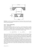
50 µs
55 µs
60 µs
65 µs
70 µs
75 µs
80 µs
85 µs
Satellite droplet
Break-off of droplet 10V (50-85 µs)
100 µm
FIGURE 10.17 Droplet ejection sequence of HP 51626A printhead, courtesy Tseng (1998c).
Satellite
droplets
Main
droplets
FIGURE 10.18 A printed vertical line smeared by satellite droplets, courtesy Tseng (1998c).
One way to eliminate puddle formation is to coat the chamber’s outer surface with a nonwetting material.(The
inner surface of the chamber needs to remain hydrophilic for liquid refill.) However, even with this coating,
there is still no guarantee that puddle will not form. More research is underway to fully understand the
mechanism in the puddle formation process.
© 2006 by Taylor & Francis Group, LLC
Microdroplet Generators 10-15
100 µm
20 µs
30 µs
40 µs
50 µs
60 µs
80 µs
100 µs
120 µs
No
satellite
droplet
FIGURE 10.19 Droplet ejection without satellite droplets, courtesy Tseng (1998a).
Nozzle
Liquid puddle
Droplet
FIGURE 10.20 Liquid puddle formation outside the micronozzles, courtesy Tseng (1998d).
© 2006 by Taylor & Francis Group, LLC
10.3.5 Material Issues
Material issues including stress, erosion, durability, and compatibility are very complex problems in the
design of microdroplet generators.
In the area of processing, material compatibility, stress, and durability problems are commonly discussed.
Material compatibility issues result from the processing temperature, processing environment (oxidation,
reactive gas, etc.), etching method used, and adhesion ability; stress issues usually concern the processing
temperature as well as the doping condition; material durability issues are due either to the material’s intrin-
sicproperties or the mechanical forces induced during the process (i.e., fluid flow force, surface tension
force, vacuum forces, or handling force). To eliminate the material issues, much care needs to be taken in
designing the process flow, such as compensating for material stress during or after the fabrication process;
performing high-temperature processes before introducing the low temperature material; finishing aggres-
sive wet etching before metal film deposition; or using low temperature bonding material and processes to
protect IC and microdevices.
In selecting chamber materials, metals such as nickel and stainless steel have been widely employed for
different microdroplet generators due to their ease of fabrication (such as by wet etching or electroplating),
high mechanical strength, resistance to erosion by certain bases or acids, imperviousness to solvents, and
high durability in cycling operations, etc. However, owing to cost and fabrication-precision considerations,
the chamber materials of many commercial ink-jets have been changed to polymers, such as polyimide or
PMMA in recent years. As a result, chamber formation by bonding a polymer thin plate on the actuator
substrate and nozzle-array formation by laser drilling on those polymer thin plates are nowverycommon
in the ink-jet industry. Nevertheless, the bonding and laser drilling processes may encounter issues such as
bonding nonuniformity, time consuming serial laser drilling processes, and alignment limitations. Therefore,
various polymer-MEMS processes for fabricating multiple embedded chambers integrated with nozzles
have been developed; these not only simplify the fabrication process but also improve the accuracy of align-
ment and nozzle fabrication on the chamber structures. Employing double exposures (one full power, and
the other partial power) on a single SU-8 resist layer with antireflection coating in the resist–substrate inter-
face, Chuang, et al. (2003) demonstrated that embedded microchannel structures can be fabricated easily,
as shown in Figure 10.21.Thethickness of chamber roof can be controlled from 14 to 60 µm in a 2 µm
resolution.
Durability, stress, and erosion issues are the major problems concerning operation. Due to the cycling
nature of the droplet generation process, the materials chosen for actuation face challenges not only from
stress but also from fatigue. The HP Corporation reported that possible reasons for failure of the heater pas-
sivation material are cavitation and thermal stress [Bhaskar et al., 1985]. Silicon, low-stress silicon nitride, sil-
icon carbide, silicon dioxide, and some metals, are usually used to overcome these problems. In addition
to selecting proper materials, reducing sharp corners in the design is an important key to eliminating stress
concentration points and thus preventing material from cracking. The working fluid’s erosion of structural
materials is another serious issue. Lee et al. (1999) reported the erosion of the spacer material in a com-
mercial ink-jet head while using diesel fuel as working fluid. In contrast, materials including silicon and silicon
nitride used by Tseng et al. (1998c, 1998d) and Lee et al. (1999) in the microinjector are free of this problem
and can also be used with a wide variety of fluids including solvents and chemicals. Selecting materials
wisely, ordering them correctly in the process, and properly designing the materials in the microstructures
are the three primary measures for reducing material issues.
10.4 Fabrication of Micro-Droplet Generators
The structures in microdroplet generators commonly include a manifold for storing liquid, microchannels
for transporting liquid, microchambers for holding liquid,nozzles for defining droplet size and direction, and
actuation mechanisms for generating droplets. Occasionally, droplet generators may not have nozzles but gen-
erate droplets locally by energy focusing means, such as acoustic wave droplet generators [Zhu et al., 1996].
Before micromachining processes became widely used, most processes for fabricating microdroplet generators
10-16 MEMS: Applications
© 2006 by Taylor & Francis Group, LLC
followed the same general method: nozzle plates, fluid handling plates, and actuation plates are manufactured
separately and then integrated into a single device. However, as the nozzle resolution becomes finer, bond-
ing processes pose severe alignment, yield, and material problems as well as IC compatibility issues. On
the other hand, the interconnection lines may not have enough space to fan out from each chamber when
nozzle resolution is higher than 600 dpi. As a result, monolithic methods for fabricating high resolution IC
integrated droplet generators have become very important. The following sections introduce examples of
different fabrication techniques.
10.4.1 Multiple Pieces
Figure 10.22 schematically shows the traditional method of fabricating microdroplet generators by bonding
separately fabricated pieces [Tseng, 1998d]. In this process, actuation plates are fabricated separately from
the nozzle plates. In the thermal bubble jet, heaters are usually sputtered or evaporated and then patterned
with an IC circuit on the bottom plate; piezo, thermal buckling, electrostatic, and inertial actuators consist
of more complex structures, such as piezo disks, thin plate structures, or cantilever beams. Nozzles are fabri-
cated by electroforming [Ta et al., 1988], molding, or laser drilling [Keefe et al., 1997]. These separately
processed pieces are assembled either by using intermediate layers of polymer spacer material [Siewell et al.,
1985; Askeland et al., 1988; Hirata et al., 1996; Keefe et al., 1997] or directly adhering several pieces
through anodic bonding [Kamisuki et al., 1998, 2000], fusion bonding [Gruhler et al., 1999], eutectic bond-
ing, or low temperature chemical bonding. However, most of the bonding methods are chip-level rather than
wafer-level processes and face challenges of alignment, bonding quality, and material–process compati-
bility. As the nozzle resolution becomes higher than 600dpi, alignment accuracy approaching 4 µm (10% of
the nozzle pitch) becomes difficult to attain. Higher alignment accuracy significantly increases the fabrication
cost, especially for the chip-level process. Bonding quality is another important issue affecting the fabrication
yield of large array and high-resolution devices. Additionally, the bonding materials (mostly polymers)
Microdroplet Generators 10-17
Anti-reflection coating
SU-8
Anti-reflection coating
Substrate
Standard UV exposure
Partial UV exposure
(a)
(b)
(c)
(d)
Stacked channel
Channel release
(e)
(f)
46.5 µµm
23 µµm
(g)
FIGURE 10.21 (a)–(f) Fabrication process of polymer multiple embedded microchambers and (g) fabricated
chambers, courtesy Chuang et al. (2003).
© 2006 by Taylor & Francis Group, LLC
chosen must be suitable for the application environments and working fluids. Finally, bonding processes
involving heat, pressure, high voltage, or chemical situations restrict IC integration with the droplet gen-
erators, and the IC integration is essential for large-array and high resolution applications.
10.4.2 Monolithic Fabrication
To address the problems inherent in using multiple pieces, monolithic processes utilizing micromachin-
ing technology have been widely employed since the early 1990s. Two primary monolithic methods have
been introduced: one combines bulk and surface micromachining and the other uses bulk microma-
chining and the deep UV lithography associated with electroforming (or UV lithography only).
For example, Tseng et al. (1998d) combined surface and bulk micromachining to fabricate a micro-
droplet generator array with potential nozzle resolution up to 1200 dpi (printing resolution can be 2400
dpi or higher). This design used double bulk micromachining processes to fabricate the fluid handling
system, including the manifold, microchannels, and microchambers. Surface micromachining, on the
other hand, was used for fabricating heaters, interconnection lines, and nozzles. The whole process was
finished on (100) crystal orientation silicon wafers. Figures 10.23 and 10.24 show the three-dimensional
structure of the microinjectors and the monolithic fabrication process respectively. The ejection of 0.9 pl
droplets has also been demonstrated by Tseng et al. (2001b) using the high-resolution microinjectors. The
structural materials used in the microinjector are silicon, silicon nitride, and silicon oxide, which are
durable in high temperature and suitable for various liquids (even some harsh chemicals). Using this
device, ICs can be easily integrated on the same silicon substrate.
10-18 MEMS: Applications
a1: Metal mold fabrication
a2: Sacrificial film pattern
a3: Nozzle plate plating
a4: Nozzle plate de-mold
Nozzle plate and actuator
plate bonding
b1: Substrate passivation
b2: Actuator fabrication
b3: Spacer pattev
FIGURE 10.22 Conventional fabrication process flow of microdroplet generators.
© 2006 by Taylor & Francis Group, LLC
The second primary method can be found in Lee’s (1999) work. This process used multiexposure and sig-
nal development (MESD) lithography to define microchannel and microchamber structures (photoresist
as sacrificial layer) and constructed the physical structures with electroformed metal. The manifold was
manufactured from the wafer’s backside by electrochemical methods [Lee et al., 1995]. This device also
demonstrated a capacity for very high-resolution arrays and compatibility with the IC process. Another
method, using photoresist as sacrificial layer and polyimide as structure layer, was introduced by Chen et al.
(1998) for high resolution and IC compatible applications.
10.5 Characterization of Droplet Generation
Droplet trajectory, volume, ejection direction, and ejection sequence/velocity are four important quanti-
tative measures of the ejection quality of microdroplet generators. The following sections briefly introduce
the basic methods for testing droplet generation.
10.5.1 Droplet Trajectory
Droplet trajectory can be visualized by directing a flashing light on the ejection stream, as shown in
Figure 10.25 [Tseng et al., 1998a]. The white dots in Figure 10.26 show the visualized droplet stream. The
visualized droplet trajectory follows an exponential curve that is very different from the parabolic curve
expected for normal sized objects with a similar initial horizontal velocity. Tseng et al. (1998a) also esti-
mated droplet trajectory by solving a set of ordinary differential equations from the balance of horizon-
tal and vertical forces on a single droplet flying through air.
From this analysis, the vertical position Y and horizontal position X of the droplet can be expressed by
the following equations:
Y ϭ U
v
∞
΄
t Ϫ
ᎏ
U
g
v
∞
ᎏ
1 Ϫ e
ᎏ
Ϫ6
m
πµ
r
0
ᎏ
t
΅
(10.1)
X ϭ
ᎏ
U
6
π
H
µ
0
m
r
0
ᎏ
1 Ϫ e
ᎏ
Ϫ6
m
πµ
r
0
ᎏ
t
(10.2)
where g is the acceleration due to gravity, t is the time, m is the mass and r
0
is the radius of the droplet,
µ
is the viscosity of air,U
v
∞
ϭ
ᎏ
6
m
πµ
g
r
0
ᎏ
is the droplet terminal velocity,and U
H0
is the initial horizontal veloc-
ity. The trajectory determined by the experiment is drawn in Figure 10.26 and fits the visualized tra-
jectory well except at the end, suggesting the interaction among droplets. From this simple analysis,
the maximum flying distance of a droplet with a known diameter can be estimated as:
X
max
ϭ ϭ (U
H0
r
2
0
), (10.3)
2
ρ
liquid
ᎏ
9
µ
air
U
H0
m
ᎏ
6
πµ
r
0
Microdroplet Generators 10-19
Liquid
entrance
Manifold
Narrow
heater
Wide
heater
Nozzle
Chamber
Common
line
Electrode
Liquid
FIGURE 10.23 Schematic three-dimensional structure view of microinjectors, after Tseng (1998c).
© 2006 by Taylor & Francis Group, LLC
when t ϳ ∞. Here the maximum distance is proportional to the droplet velocity and droplet radius
to the second power. For different droplet sizes with the same initial velocity, the maximum flying
distance of smaller droplets decreases very fast. To obtain 1 mm flying distance, the droplet with
10 m/s initial velocity needs a minimum radius of 2.7 µm. From the above estimation, droplet size
should be maintained above a certain value to ensure enough flying distance for printing. Printing
with very fine droplets (diameter smaller than a couple of micrometers) requires either increasing
the droplets’ initial velocity or printing in a special vacuum environment to overcome air drag.
10-20 MEMS: Applications
(d)
(
e
)
Nozzle formation & pad open
KOH etch manifold, PSG remove
(b)
Heater & interconnection formation
KOH etch enlarge chamber depth
(c)
PSG & low-stress-nitride deposition
(a)
Si
Top view
Cross section A-A′
A
A′
FIGURE 10.24 Fabrication process flow of monolithic microinjectors, after Tseng (1998c).
© 2006 by Taylor & Francis Group, LLC
Microdroplet Generators 10-21
CCD camera
Flashlight
Microinjector
Droplet trajectory
FIGURE 10.25 Experimental setup for droplet stream visualization.
U
H
0
0
1
2
3
4
5
cm
Satellite
droplets
Main
droplets
Calculated curve
Calculated
curve
0 2 4 5 6 8
cm
731
FIGURE 10.26 Visualized droplet stream and estimated trajectory of a microdroplet generator, courtesy Tseng (1998a).
10.5.2 Ejection Direction
Droplet direction can be determined by the visualized trajectory. Many parameters, including nozzle shape,
roughness, aspect ratio, and wetting property as well as actuation direction and chamber design,affect droplet
direction. In general, symmetric structure design and accurate alignment can help control droplet direction.
10.5.3 Ejection Sequence/Velocity and Droplet Volume
To characterize the detailed droplet ejection sequence, a visualization system [P H. Chen et al., 1997b, Tseng
et al., 1998c] as shown in Figure 10.27 has been widely used. In this system, an LED was placed under the
© 2006 by Taylor & Francis Group, LLC
droplet generator to back-illuminate the droplet stream. Two signals synchronized with adjustable time
delay were sent to a microinjector and an LED respectively. Droplets were ejected continuously from a
droplet generator, and the droplet images were frozen by the LED’s flashing light at specified time delays,
as shown in Figure 10.17.Droplet volume can be determined from the images by assuming the droplet is
axi-symmetric, or from weighing certain numbers of droplets. Droplet velocity can be estimated by meas-
uring the difference in flying distance of the droplet fronts in two succeeding images.
10.5.4 Flow Field Visualization
Flow field visualization is one of the most direct and effective tools to better understand flow properties
such as cross talk, actuation sequence, liquid refill, and droplet formation inside microdroplet generators.
Flow visualization in small scale presents some difficulties that do not occur in large scale, such as lim-
ited viewing angles, impossible to generate light sheet, reflection from the particles trapped on the wall,
short response time, and small spatial scale. Meinhart et al. (2000) adopted a micrometer resolution par-
ticle image velocimetry system to measure instantaneous velocity fields in an electrostatically actuated
ink-jet head. The system introduced 700 nm diameter fluorescent particles for flow tracing; the spatial as
well as temporal resolutions of the image velocimetry are 5–10 µm and 2–5 µs respectively. The four pri-
mary phases of ink-jet operation — infusion, inversion, ejection, and relaxation — were clearly captured
and quantitatively analyzed.
10.6 Applications
More than a hundred applications for microdroplet generators have been explored. This section sum-
marizes some of them.
10-22 MEMS: Applications
CCD
Camera
VCR
Microscope
LED
Microinjector
Signal A
Signal B
Synchronizer
FIGURE 10.27 Experimental setup for droplet ejection sequence visualization.
© 2006 by Taylor & Francis Group, LLC
10.6.1 Ink-jet Printing
Ink-jet printing, which involves arranging small droplets on a printing medium to form texts, figures, or
images, is the most well-known microdroplet application. The smaller and cleaner the droplets are, the
sharper the printing is. However, smaller droplets cover a smaller printing area and thus require more
printing time. Therefore in printing, high-speed microdroplet generation with stable and clean micro sized
droplets is desired for fast and high quality printing. The printing media can be paper, textile, skin, cans or
other surfaces that can adsorb or absorb printing solutions. Ink-jet printing generated revenues of more
than $10 billion worldwide in 2000 and will keep growing in the future.
10.6.2 Biomedical and Chemical Sample Handling
The application of microdroplet generators in biomedical sample handling is an emerging field that has
drawn much attention in the past few years. Many research efforts have focused on droplet volume control,
droplet size miniaturization, compatibility issues, the variety of samples, and high-throughput parallel
methods.
Luginbuhl et al. (1999), Miliotis et al. (2000), and Wang et al. (1999) developed piezo- and pneumatic-
type droplet injectors respectively for mass spectrometry. Figure 10.28 schematically shows the design of
the injectors,which generate submicron to micron sized bioreagent droplets for sample separation and analy-
sis in a mass spectrometer, as shown in Figure 10.29. Luginbuhl et al. (1999) employed silicon bulk micro-
machining to fabricate silicon nozzle plates and Pyrex glass actuation plates, while Wang et al. (1999)
employed a combination of surface and bulk micromachining to fabricate the droplet generator. These
injectors are part of the lab-on-the-chip system for incorporating microchips with macroinstruments.
Microdroplet generators were also used by Koide et al. (2000), Nilsson et al. (2000), Goldmann et al.
(2000), and Szita et al. (2000) for the accurate dispensing of biological solutions. Piezo- and thermal-type
injectors were used in those investigations for protein, peptide, enzyme, or DNA dispensing. With an oper-
ation principle similar to ink-jet printing, the devices provided for precisely dispensing and depositing a
Microdroplet Generators 10-23
Pressure chamber
Nozzle
Liquid path
PZT disc transducer
Silicon
Glass
FIGURE 10.28 The injector design for mass spectrometry, after Luginbuhl (1999).
MS
inlet
Droplet generators
Droplets
FIGURE 10.29 Operation principle of mass spectrometry using microdroplet generators.
© 2006 by Taylor & Francis Group, LLC
single biological droplet onto a desired medium, and they also could dispense droplet arrays. The arrayed
bioreagents can be bioprocessed further for high-throughput analysis.
Continuous jet-type droplet generators were reported by Asano et al. (1995) to effectively focus and sort
particles by using the electrostatic force. The experimental setup is shown in Figure 10.30. A syringe pump
pressurizes the sample fluid to pass through a nitrogen sheath flow for focusing, and then the sample is
ejected from a piezoelectric transducer disturbed nozzle to form droplets. Droplets containing the desired
particles were charged at the breakup point and deflected into collectors. The reported separation prob-
ability for 5, 10, and 15 µm particles can be as high as 99%. However, the inner jet diameter limits the par-
ticle size for separation. Other than solid particle separation, this method potentially can be applied to
cell sorting for biomedical applications.
In addition to biomedical reagent handling, microdroplet generators were widely used in chemical handling.
For example, Shah et al. (1999) used an ink-jet system to print catalyst patterns for electroless metal deposition.
This system used a commercial ink-jet printhead to ejecte a Pt solution as a seed layer for Cu electroless plating.
The lines produced by this method were reported to be 100 µm wide and 0.2–2µm high.
10.6.3 Fuel Injection and Mixing Control
Microdroplet generators used for fuel injection can dispense controllable and uniform droplets, which
are important for mixing and combustion applications.
10-24 MEMS: Applications
Pressured N
2
Sample
Laser
PMT tube
Charge plate
Deflection plate
Piezo vibrator
Collectors
Droplets
with particles
FIGURE 10.30 Particle sorting using droplet generators, after Asano (1995).
© 2006 by Taylor & Francis Group, LLC
Combustion efficiency depends on the mixing rate of the reactants. The reactants in a shear flow are first
entrained by large vortical structures (Brown and Roshko, 1974) and then mixed by fine scale eddies. The
entrainment can be greatly enhanced by controlling the evolution of large-scale vortices either actively (Ho
et al., 1982) or passively (Ho et al., 1987). The effectiveness of controlling large-scale vortical structures for
increasing combustion efficiency has also been experimentally demonstrated (Shadow et al., 1987). Although
much work has been done on improving the mixing efficiency in combustion chambers, improving the small
scale mixing and reducing the evaporation time of liquid fuel remain great challenges in combustion
research.
Traditional injectors with nozzle diameters of around tens to hundreds of µms can neither supply uni-
form microdroplets for reducing evaporation time and fine scale mixing nor eject droplets that can be
controlled individually to modulate vortex structure [Lee et al., 1999]. To overcome those limitations,
Tseng et al. (1996) proposed a microdroplet injector array fabricated by the micromachining technolo-
gies used for fuel injection. The droplets ejected from microinjectors are uniform and the diameter can
be from µm to tens of µms, which is close to the micro scale of small turbulence eddies. The fine scale
mixing can be carried out by the reaction of the small turbulence eddies directly with the microdroplets.
The smaller, more uniform droplets increase the overall size of the evaporation surface and thus greatly
reduce evaporation time. In addition, an appropriate arrangement of the microinjectors around the noz-
zle of a dump combustor (Figure 10.31) provides spatially coherent perturbations to control the large
vortices. Two types of coherent structures, spanwise and streamwise vortices, can be influenced by impos-
ing subharmonics of the air jet’s most unstable instability frequency. Control of the spanwise vortices can
be accomplished by applying temporal amplitude modulation on injection. If the ejecting phases of the
microdroplets along the azimuthal direction are the same, the mode zero instability (Brown et al., 1974)
is enhanced. Imposing a certain defined phase lag on these microinjectors generates higher mode insta-
bility (Brown et al., 1974) waves, which are usually beneficial for mass transfer enhancement. Since about
1000 injectors are placed around the nozzle, the spatial modulation in the azimuthal direction can per-
turb the streamwise vortices. The interaction of streamwise and spanwise vortices by microinjectors cre-
ates fine scale mixing.
Microdroplet Generators 10-25
Controller
Fuel
Air
Acoustic
driver
Coherent
flow structure
Micro injectors
Fuel droplet
injections
FIGURE 10.31 Control of mixing and fuel injection by microdroplet generators, after Tseng (1996).
© 2006 by Taylor & Francis Group, LLC
10.6.4 Direct Writing and Packaging
Micro droplet generators offer an alternative to lithography for electronics and opto-electronics manufactur-
ing. This approach has the advantages of precise volume control of dispensed materials, data driven flex-
ibility, low cost, high speed, and low environmental impact, as described by Hayes and Cox (1998). The
materials have been demonstrated for the application to manufacturing processes including adhesive for
component bonding, filled polymer systems for direct resistor writing and oxide deposition, and solder for
solder bumping of flip-chips, BGAs (ball grid arrays), PCBs (printed circuit boards), and CSPs (chip-scale-
packages) [Hays et al., 1999; Teng et al., 1988]. In those printings, the desired temperature is 100ϳ200°C,
and the viscosity of the fluids needs to be around 40 cps; in some cases, an inert process environment, such
as nitrogen flow, is required to protect the materials from oxidation.
Through direct writing by ink-jet printing, the difficulty of fabrication from photolithography or screen-
printing processes for solar cell metallization and LEP (light emitting polymer) deposition of LEPD (light
emitting polymer displays) can be easily eliminated. In solar cell metallization, metalo-organic decomposition
(MOD) silver ink was used to ink-jet print directly onto solar cell surfaces and thus avoid p-n junction degra-
dation in the traditional screen printing method requiring firing temperatures of 600–800°C. Ink-jet printing
also provides for the formation of a uniform line film on rough solar cell surfaces [Tang et al., 1988a, 1988b;
Somberg et al., 1990], which is not easy to achieve using traditional photolithography.
On the other hand, organic light emitting devices requiring the deposition of multiple organic layers to
perform full color operation present similar problems. Due to the organic layers’ solubility in many solvents
and aqueous solutions, conventional methods, such as photolithography, screen printing and evaporation,
that require a wet patterning process are not compatible with them on the same substrate [Hebner et al.,1998;
Shimoda et al., 1999; Kobayashi et al., 2000]. Thus direct writing of organic materials by ink-jet printing
becomes one of the promising solutions for providing a safe patternable process without wet etching.
However, owing to the pinholes that appear on the patterned materials, high quality polymer devices may
not be easily ink-jet printed. Yang’s group proposed combining an ink-jet printed layer with a uniform spin
coated polymer layer to overcome this problem [Bharathan et al., 1998]. In such a system, the uniform
layer serves as a buffer layer to seal the pinholes, and the ink-jet-printing layer contains the desired patterns
[Bharathan et al., 1998].
10.6.5 Optical Component Fabrication and Integration
Integrated microoptics has become a revolutionary concept in the optics field because it provides the
advantages of low cost, miniaturization, improved spatial resolution and time response, and a reduced
assembly process that is not possible by traditional means. As a result, fabricating and integrating minia-
turized optical components with performance similar to or better than traditional components are criti-
cal issues in integrated microoptics systems. Standard bulk or surface micromachining provides various
ways to fabricate active/passive micromirrors, wave-guides, and Fresnel lenses, but making a refractive
lens with curved surfaces is not easy. Compared to photolithography, which utilizes a patterned and
melted photoresist column as the lens, the ink-jet printing method allows more flexibility in process
design, material choices, and system integration. Cox et al. employed ink-jet printing technology to eject
heated polymer material in fabricating a micro lenslet array [Cox et al., 1994; Hays et al., 1998]. The shape
of the lens was controlled by the viscosity of the droplets at the impact point, the substrate wetting con-
dition, and the cooling/curing rate of the droplets [Hays et al., 1998]. A 70–150 µm diameter lens has been
successfully fabricated with a density greater than 15,000/cm
2
and focal lengths between 50 and 150 µm.
Wave-guides using ink-jet technology also have been demonstrated by Cox et al. (1994).
Since optical components with varying properties can be selectively deposited onto the desired region,
integration of those components with fabricated ICs or other devices is possible and efficient.
10.6.6 Solid Free Forming
Not only two-dimensional patterns but also three-dimensional solid structures can be generated by
microdroplet generators. Orme et al. (1993) and Marusak et al. (1993) reported the application of molten
10-26 MEMS: Applications
© 2006 by Taylor & Francis Group, LLC
metal drops for solid free form fabrication. Evans’ group demonstrated the application of continuous and
drop-on-demand ink-jets for ceramic printing to fabricate 3-D structures as well as functionally graded
materials [Blasdell et al., 2000; Mott et al., 1999]. Yamaguchi et al. (2000) used metal jets to print func-
tional three-dimensional microstructures; Figure 10.32 shows the operation principle. Yamaguchi et al.
(2000) proposed employing multijets for structure and sacrificial material deposition to print an over-
hanging structure, while Fuller et al. (2000) used laminated PMMA film as the supporting material for
the ejection of metal cantilever beams. The fabrication principle is shown in Figure 10.33.
10.6.7 Manufacturing Process
Droplet generators also provide novel ways of material processing. For example, submicron ceramic par-
ticles can be plasma sprayed for surface coating, as introduced by Blazdell and Juroda [Blazdell et al., 2000].
Microdroplet Generators 10-27
Metal jet
Nozzle
Diaphragm
Piezo disc
Metal chamber
Micro structure
FIGURE 10.32 Operation principle of three-dimensional structure fabrication by microdroplet generator, after
Yamaguchi (2000).
Inkjet head
(a) PMMA deposition
Draw down bar
PMMA
(b) PMMA lamination
(c) Particle deposition
by inkjet
(d) Structure release
FIGURE 10.33 Fabrication of three-dimensional structures by droplet ejection and polymer lamination, after Fuller
(2000).
© 2006 by Taylor & Francis Group, LLC
The operation principle is shown in Figure 10.34. A continuous jet printer was used for droplet formation
from ceramic solution. The ceramic stream was delivered into the hottest part of the plasma jet and then
sprayed onto the working piece. Splats from the plasma spray are claimed to be similar in morphology to
those produced using conventional plasma spraying of a coarse powers, but they are significantly smaller,
which may impart unique characteristics such as extension of solid state solubility, refinement of grain
size, formation of metastable phases, and high concentration of point defects [Blazdell et al., 2000].
10.6.8 IC Cooling
Conventionally, blowing fans and fins are widely used for cooling IC chips, especially in CPUs. Recently, as
heating power has increased greatly with increasing CPU size, more advanced methods, such as heat pipes,
CPL, and impinging air jets, have been introduced for quick heat removal. However, no matter how the
designs improve, the upper limit of of those devices’ heat removal ability is in the order of tens of W/cm
2
. In
addition, as chips become larger, detecting hot spots and selectively removing the heat only from hot regions
10-28 MEMS: Applications
Gas
Inkjet
Droplets
Plasma jet
Deposit
Arc
discharge
FIGURE 10.34 Operation principle of plasma spraying by microdroplet generators, after Blazdell (2000).
2 cm
2 cm
Micro droplet generation chip
IC chip with integrated
surface temperature sensors
Micro injectors
Signal and energy transport bus
Parallel packaging
Droplet
ejection
for cooling
FIGURE 10.35 Conceptual design of IC cooling by microdroplet injections.
© 2006 by Taylor & Francis Group, LLC
to preserve energy is highly desired but difficult to perform using traditional means. Transportating latent
heat through the droplet evaporation process is a promising new way of doing this. This method can in prin-
ciple remove three to four orders more heat than conventional means. Further, the cooling spot can be
selected and monitored by an integrated micro temperature sensor and IC array. The conceptual design by
Tseng (2001c), as shown in Figure 10.35, used a two-dimensional array of microinjectors to selectively deposit
liquid droplets onto the chip surface. The frequency and number of droplets applied can be adjusted to main-
tain a dry chip surface with a constant temperature. The estimated maximum heat removed by this device
is around 300,000 W/cm
2
, more than 1000 times more than by conventional means. The temperature sen-
sors and control circuits can be fabricated on the same chip to form a self-contained smart system.
10.7 Concluding Remarks
Droplet generators are important fluid handling devices for precise liquid dosing control. MEMS tech-
nology makes micro sized droplet generators possible and popular for many applications. Various tech-
niques for droplet generation, including piezoelectric, thermal bubble, thermal buckling, focused acoustic
wave, electrostatic, and inertial actuation, have been employed. Compared to the other methods, thermal
bubble generation has larger actuation deformation, simpler design/fabrication, and fewer limitations on
chamber volume, but it has the drawbacks of temperature sensitivity and of being influenced by the liq-
uid’s properties. The piezo-type jet has the advantages of high frequency response, controllable droplet
size, and free of satellite drops, but its limitations on finite actuation deformation thus restrict the cham-
ber volume’s miniaturization. Electrostatic and thermal bulking jets have size limitations similar to piezo
jets. The electrostatic jet has the benefit of low power consumption, but both it and the thermal bulking
jet have limited frequency response due to their size restrictions. The acoustic wave droplet generator, on
the other hand, is not fully developed and stable enough for commercial applications, while the inertial
actuation method’s operation principle limits its miniaturization. More types of microdroplet generators
are being developed, and they may one day replace the ones we have been using for decades.
Physical properties, design issues, and manufacturing problems are important concerns in the design
and fabrication of microdroplet generators. The associated issues including frequency response, cross
talk, satellite droplets, puddle formation, material selection, and integration require great care at all lev-
els of design and fabrication. MEMS technology provides some key solutions to those practical issues.
Many applications and potential applications have made microdroplet generators important and excit-
ing since their inception. Ink-jet printing, the traditional application, has generated huge amounts of rev-
enue. Moreover, hundreds of promising applications have been emerging, including bioreagent handling,
fine chemical handling, drug delivery, direct writing, solid free form, IC cooling, and fuel injection. Many
exciting applications of microdroplet generators are yet to be discovered.
References
Allen, R.R., Meyer, J.D., and Knight, W.R. (1985) “Thermodynamics and Hydrodynamics of Thermal Ink
Jets,” Hewlett-Packard J., May, pp. 21–27.
Asai, A. (1989) “Application of the Nucleation Theory to the Design of Bubble Jet Printers,” Jpn. J. Appl.
Phys., 28, pp. 909–15.
Asai, A. (1991) “Bubble Dynamics in Boiling under High Heat Flux Pulse Heating,” ASME J. Heat Transfer,
113, pp. 973–79.
Asai, A. (1992) “Three-Dimensional Calculation of Bubble Growth and Drop Ejection in a Bubble Jet
Printer,” Trans. ASME, 114, pp. 638–41.
Asai, A., Hara, T., and Endo, I. (1987) “One Dimensional Model of Bubble Growth and Liquid Flow in
Bubble Jet Printers,” Jpn. J. Appl. Phys., 26, pp. 1794–1801.
Asai, A., Hirasawa, S., and Endo, I. (1988) “Bubble Generation Mechanism in the Bubble Jet Recording
Process,” J. Imag. Tech., 14, pp. 120–24.
Microdroplet Generators 10-29
© 2006 by Taylor & Francis Group, LLC
Asano, K., Funayama, Y., Yatsuzuka, K., and Higashiyama, Y. (1995) “Spherical Particle Sorting by Using
Droplet Deflection Technology,” J. Electrostat., 35, pp. 3–12.
Ashley, C.T., Edds, K.E., and Elbert, D.L. (1977) “Development and Characterization of Ink for an
Electrostatic Ink Jet Printer,” IBM J. Res. Dev., 21, pp. 69–74.
Askeland, R A., Childers W D., and Sperry, W R. (1988) “The Second-Generation Thermal InkJet
Structure,” Hewlett-Packard J., August, pp. 28–31.
Bharathan, J., and Yang, Y. (1998) “Polymer Electroluminescent Devices Processed by Inkjet Printing: 1.
Polymer Light-Emitting Logo,” Appl. Phys. Lett., 72, pp. 2660–62.
Bhaskar, E.V., and Aden, J.S. (1985) “Development of the Thin-film Structure for the Thinkjet Printhead,”
Hewlett-Packard J., May, pp. 27–33.
Blazdell, P.F., and Evans, J.R.G. (2000) “Application of a Continuous Ink Jet Printer to Solid Freefroming
of Ceramics,” J. Mater. Process. Technol., 99, pp. 94–102.
Blazdell, P., and Kuroda, S. (2000) “Plasma Spraying of Submicron Ceramic Suspensions Using a
Continuous Ink Jet Printer,” Surf. Coat. Technol., 123, pp. 239–46.
Bogy, D.B., and Talke, F.E. (1984) “Experimental and Theoretical Study of Wave Propagation Phenomena
in Drop-On Demand Ink Jet Devices,” IBM J. Res. Dev., 28, pp. 314–21.
Brown, G.L., and Roshko, A. (1974) “On Density Effects and Large Structure in Turbulent Mixing Layers,”
J. Fluid Mech., 64, pp. 775–816.
Buehner, W.L., Hill, J.D., Williams, T.H., and Woods, J.W. (1977) “Application of Ink Jet Technology to a
Word Processing Output Printer,” IBM J. Res. Dev., 21, pp. 2–9.
Bugdayci, N., Bogy. D.B., and Talke, F.E. (1983) “Axisymmetric Motion of Radially Polarized Piezoelectric
Cylinders Used in Ink jet Printing,” IBM J. Res. Dev., 27, pp. 171–80.
Buskirk, W A., Hackleman, D E., Hall, S T., Hanarek, P H., Low, R N., Trueba, K E., and Van de
Poll, R R. (1988) “Development of a High-Resolution Thermal Inkjet Printhead,” Hewlett-Packard
J., Oct., pp. 55–61.
Carmichael, J.M. (1977) “Controlling Print Height in an Ink Jet Printer,” IBM J. Res. Dev., 21, pp. 52–55.
Chen, J K., and Wise, K.D. (1995) “A High-Resolution Silicon Monolithic Nozzle Array for Inkjet
Printing,” The 8th International Conference on Solid-State Sensors and Actuators, and Eurosensors 9,
June 25–29, Stockholm, pp. 321–24.
Chen, J K., Juan, W., Kubby, J., and Hseih, B C. (1998) “A Monolithic Polyimide Nozzle Aray for Inkjet
Printing,” Tech. Dig. IEEE Solid State Sensor and Actuator Workshop, pp. 308–11, June 8–11, Hilton
Head Island, SC.
Chen, P H., Chen, W C., and Chang, S H. (1997a) “Bubble Growth and Ink Ejection Process of a
Thermal Ink Jet Printhead,” Int. J. Mech. Sci., 39, pp. 687–95.
Chen, P H., Chen, W C., and Chang, S H. (1997b) “Visualization of Drop Ejection Process of a Thermal
Bubble Ink Jet Printhead,” Proc. The 1st Pacific Symp. Flow Visualization and Image Processing,
Honolulu, pp. 132–37, February 22–26.
Chen, P H., Chen, W C., Ding, P P., and Chang, S H. (1998) “Droplet Formation of a Thermal
Sideshooter Inkjet Printhead,” Int. J. Heat Fluid Flow, 19, pp. 382–90.
Chen, P H., Peng, H Y., Liu, H Y., Chang, S L., Wu, T I., and Cheng C H. (1999) “Pressure Response
and Droplet Ejection of a Piezoelectric Inkjet Printhead,” Int. J. Mec. Sci., 41, pp. 235–48.
Chuang, Y J., Tseng, F G., Cheng, J H., and Lin, W K. (2003) “A Novel Fabrication Method of SU-8
Stacked Micro Channels By UV Dosage Control,” Sensors Actuators A, 103, pp. 64–69.
Cox, W.R., Chen, T., Hayes, D.J., MacFarlane, D.L., Narayan, V., and Jatum, J.A. (1994) “Microjet
Fabrication of Microlens Arrays,” IEEE Photon. Technol. Lett., 6, pp. 1112–14.
Curry, S.A., and Portig, H. (1977) “Scale Model of an Ink Jet,” IBM J. Res. Dev., 21, pp. 10–20.
Darling, R.H., Lee, C H., and Kuhn, L. (1984) “ Multiple-Nozzle Ink Jet Printing Experiment,” IBM J. Res.
Dev., 28, pp. 300–6.
Fromm, J.E. (1984) “Numerical Calculation of the Fluid Dynamics of Drop-On Demand Jets,” IBM J. Res.
Dev., 28, pp. 322–33.
Fuller, S., and Jacobson, J. (2000) “Ink Jet Fabricated Nanoparticle MEMS,” Proc. IEEE MEMS Conference,
pp. 138–41, January 23–27, Kyoto, Japan.
10-30 MEMS: Applications
© 2006 by Taylor & Francis Group, LLC
Goldmann, T., and Gonzalez, J.S. (2000) “DNA-Printing: Utilization of a Standard Inkjet Printer for the
Transfer of Nucleic Acids to Solid Supports,” J. Biochem. Biophys. Methods, 42, pp. 105–10.
Gruhler, H., Hey, N., Muller, M., Bekesi, S., Freygang, M., Sandmaier, H., and Zengerle, R. (1999)
“Topspot: A New Method for the Fabrication of Biochips,” Proc. IEEE MEMS ’99, pp. 7413–17,
January 17–21, Orlando, Florida.
Hays, D.J., and Cox, W.R. (1998) “Micro Jet Printing of Polymers for Electronics Manufacturing,”
Proceedings of 3rd international Conference on Adhesive Joining and Coating Technology in Electronics
Manufacturing, pp. 168–73, September 21–30, Binghamton, NY.
Hayes, D.J., Grove, M.E., and Cox, W.R. (1999) “Development and Application by Ink-Jet Printing of
Advanced Packaging Materials,” 1999 International Symposium on Advanced Packaging Materials,
pp. 88–93, March 14–17, Chateau Elan, Braelton, Georgia.
Hebner, T.R., Wu, C.C., Marcy, D., Lu, M.H., and Sturm, J.C. (1998) “Ink-Jet Printing of Doped Polymer
for Organic Light Emitting Devices,” Appl. Phys. Lett., 72, pp. 519–21.
Hirata, S., Ishii, Y., Matoba, H., and Inui, T. (1996) “An Ink-Jet Head Using Diaphragm Microactuator,”
Proc. of the 9th IEEE Micro Electro Mechanical Systems Workshop, pp. 418–23, February 11–15, San
Diego.
Ho, C.M., and Gutmark, E. (1987) “Vortex Induction and Mass Entrainment in a Small Aspect Ratio
Elliptic Jet,” J. Fluid Mech., 179, pp. 383–405.
Ho, C.M., and Huang, L.S. (1982) “Subharmonics and Vortex Merging in Mixing Layers,” J. Fluid Mech.,
119, pp. 443–73.
Kamisuki, S., Fuji, M, Takekoshi, T., Tezuka, C., and Atobe, M. (2000) “A High Resolution,
Electrostatically-Driven Commercial Inkjet Head,” Proc. IEEE MEMS ’00, pp. 793–98, January
23–27, Miyazaki, Japan.
Kamisuki, S., Hagata, T., Tezuka, C., Nose, Y., Fuji, M., and Atobe, M. (1998) “A Low Power, Small,
Electrostatically-Driven Commercial Inkjet Head,” Proc. IEEE MEMS ’98, pp. 63–68, January
25–29, Heidelberg, Germany.
Karz, R.S., O’Neill, J.F., and Daneile, J.J. (1994) “Ink Jet Printhead with Ink Flow Direction Valves,” U. S.
Patent No. 5,278,585.
Keefe, B J., Ho, M F., Courian, K J., Steinfield, S W., Childers, W D., Tappon, E R., Trueba, K E.,
Chapman, T I., Knight, W R., and Moritz, J G. (1997) “Inkjet Printhead Architecture for High
Speed and High Resolution Printing,” U.S. Patent No. 5,648,805.
Kobayashi, H., et al. (2000) “A Novel RGB Multicolor Light-Emitting Polymer Display,” Synth. Met.,
111–112, pp. 125–28.
Koide, A., Sasaki, Y., Yoshimura, Y., Miyake R., and Terayama, T. (2000) “Micromachined Dispenser with
High Flow Rate and High Resolution,” Proc. IEEE MEMS ’00, pp. 424–28, January 23–27, Miyazaki,
Japan.
Krause, P., Obermeier, E., and Wehl, W. (1995) “Backshooter: A New Smart Micromachined Single-Chip
Inkjet Printhead,” The 8th International Conference on Solid-State Sensors and Actuators, and
Eurosensors 9, pp. 325–28, June 25–29, Stockholm.
Lee, F.C., Mills, R.N., and Talke, F.E. (1984) “The Application of Drop-On Demand Ink Jet Technology to
Color Printing,” IBM J. Res. Dev., 28, pp. 307–13.
Lee, H.C. (1977) “Boundary Layer Around a Liquid Jet,” IBM J. Res. Dev., 21, pp. 48–51.
Lee, J D., Lee H D., Lee H J., Yoon, J B., Han, K H., Kim, J K., Kim, C K., and Han, C H. (1995)
“A Monolithic Thermal Inkjet Printhead Utilizing Electrochemical Etching and Two-Step
Electroplating Techniques,” J. MEMS, 8, pp. 601–04.
Lee, J D., Yoon, J B., Kim, J K., Chung, H J., Lee, C S., Lee, H D., Lee, H J., Kim, C K., and Han, C H.
(1999) “A Thermal Inkjet Printhead with a Monolithically Fabricated Nozzle Plate and Self-Aligned
Ink Feed Hole,” J. MEMS, 8, pp. 229–36.
Lee, Y K., Yi, U., Tseng, F G., Kim, C.J., and Ho, C M. (1999) “Diesel Fuel Injection by a Thermal
Microinjector,” Proc. MEMS, ASME IMECE ’99, pp. 419–25, November 14–19, Nashville, Tennessee.
Levanoni, M. (1977) “Study of Fluid Flow through Scaled-Up Ink Jet Nozzles,” IBM J. Res. Dev., 21, pp.
56–68.
Microdroplet Generators 10-31
© 2006 by Taylor & Francis Group, LLC
Luginbuhl, P. et al. (1999) “Micromachined Injector for DNA Spectrometry,” IEEE Transducers ’99, pp.
1130–33, June 7–10, Sendai, Japan.
Marusak, R.E. (1993) “Picoliter Solder Droplet Dispensing,” Proceedings of The Solid Freeform Fabrication
Symposium, pp. 81–87, August 9–11, Austin.
Meinhart, C D., and Zhang H. (2000) “The Flow Structure Inside a Microfabricated Inkjet Printhead,”
J. MEMS, 9, pp. 67–75.
Miliotis, T., Eficsson, D., Marko-Varga, G., Ekstrom, S., Nilsson, J., and Laurell, T. (2000) “Interfacing
Protein and Peptide Separation to Maldi-tof MS Using Microdispensing and On-Target
Enrichment Strategies,” Proc.
µ
TAS ’00, pp. 387–91, May 14–18, Enschede, The Netherlands.
Mirfakhraee, A. (1989) Growth and Collapse of Vapor Bubbles in Ink-Jet Printers, Ph.D. dissertation,
Univeristy of California, Berkeley.
Mott, M., and Evans, J.R.G. (1999) “Zirconia/Alumina Functionally Graded Material Made by Ceramic
Ink Jet Printing,” Mater. Sci. Eng. A, 271, pp. 344–52.
Myers, R.A., and Tamulis, J.C. (1984) “Introduction to Topical Issue on Non-Impact Printing
Technologies,” IBM J. Res. Dev., 28, pp. 234–40.
Nielsen, N.J. (1985) “History of ThinkJet Printhead Development,” Hewlett-Packard J., May, pp. 4–10.
Nilsson, J., Bergkvist, J., and Laurell, T. (2000) “Optimization of the Droplet Formation in a Piezo-Electric
Flow-Through Microdispenser,” Proc.
µ
TAS ’00, pp. 75–78, May 14–18.
Orme, M., and Huang, C. (1993) “Thermal Design Parameters Critical to the Development of Solid
Freefrom Fabrication of Structural Materials with Controlled Nano-Liter Droplets,” Proceedings of
The Solid Freeform Fabrication Symposium, pp. 88–94, August 9–11, Austin.
Pimbley, W.T., and Lee, H.C. (1977) “Satellite Droplet Formation in a Liquid Jet,” IBM J. Res. Dev., 21, pp.
21–30.
Rembe, C., Siesche, S.A.D., and Hofer, E.P. (2000) “Thermal Ink Jet Dynamics: Modeling, Simulation, and
Testing,” Microelectron. Reliab., 40, pp. 525–32.
Shadow, K.C., Gutmark, E., Wilson, K.J., Parr, D.M., Mahan, V.A., and Ferrell, G.B. (1987) “Effect of Shear-
Flow Dynamics in Combustion Processes,” Combust. Sci. Technol., 54, pp. 103–16.
Shah, P., Kevrekides, Y., and Benziger J. (1999) “Ink-Jet Printing of Catalyst Patterns for Electroless Metal
Deposition,” Langmuir, 15, pp. 1584–87.
Shimoda, T., Kimura M., Seki S., Kobayashi, H., Kanbe, S., and Miyahita, S. (1999) “Technology for Active
Matrix Light Emitting Polymer Displays,” IEEE IEDM ’99, pp. 107–10, December 5–8, Washington,
DC.
Siewell, G L., Boucher, W.R., and McClelland, P.H. (1985) “The ThinkJet Orifice Plate: A Part with Many
Functions,” Hewlett-Packard J., May, pp. 33–37.
Somberg, H. (1990) “Inkjet Printing for Metallization on Very Thin Solar Cells,” Photovoltaic Specialists
Conference, Conference Record of the Twenty First IEEE, pp. 666–67, May 21–25, Kissimmee,
Florida.
Sweet, R.G. (1964) “High Frequency Recording with Electrostatically Deflected Ink Jets,” Stanford
Electronics Laboratories Technical Repost No. 1722-1, Stanford University.
Sweet, R.G. (1971) “Fluid Droplet Recorder,” U. S. Patent No. 3,576,275.
Szita, N., Sutter, R., Dual, J., and Buser, R. (2000) “A Fast and Low-Volume Pipettor with Integrated
Sensors for High Precision,” Proc. IEEE MEMS ’00, pp. 409–13, January 23–27, Miyazaki, Japan.
Ta, C C., Chan, L W.,Wield, P J., and Nevarez R. (1988) “Mechanical Design of Color Graphics Printer,”
Hewlett-Packard J., August, pp. 21–27.
Teng, K.F., Azadpour, M.A., and Yang, H.Y. (1988) “Rapid Prototyping of Multichip Packages Using
Computer-Controlled, Ink Jet Direct-Write,” Proceedings of the 38th Electronics Components
Conference, pp. 168–73, May 9–11, LA, CA.
Teng, K.F., and Vest, R.W. (1988a) “Metallization of Solar Cells with Ink Jet Printing and Silver Metallo-
Organic Inks,” IEEE Trans. Components, Hybrids, Manuf. Technol., 11, pp. 291–97.
Teng, K.F., and Vest, R.W. (1988b) “Application of Ink Jet Technology on Photovoltaic Metallization,” IEEE
Electron. Device Lett., 9, pp. 591–93.
10-32 MEMS: Applications
© 2006 by Taylor & Francis Group, LLC
Tseng, F G., Linder, C., Kim, C J., and Ho, C M (1996) “Control of Mixing with Micro Injectors for
Combustion Application,” Micro-Electro-Mechanical Systems (MEMS) DSC-ASME IMECE, pp.
183–87, November 17–22, Atlanta.
Tseng, F G., Kim, C J., and Ho, C M (1998a) “A Microinjector Free of Satellite Drops and
Characterization of the Ejected Droplets,” Proc. MEMS, ASME IMECE ’98, pp. 89–95, November
15–20, Anaheim, CA.
Tseng, F G., Shih, C., Kim, C J., and Ho, C M (1998b) “Characterization of Droplet Injection Process of
a Microinjector,” in Abstract Book of 13th U.S. Congress of Applied Mechanics, pp. TB3, University of
Florida.
Tseng, F G., Kim, C J., and Ho, C M (1998c) “A Novel Microinjector with Virtual Chamber Neck,”
Technical Digest of The 11th IEEE International Workshop on Micro Electro Mechanical Systems,
pp. 57–62, January 25–29, Heidelberg, Germany.
Tseng, F G. (1998d) A Micro Droplet Generation System, Ph.D. dissertation, University of California, Los
Angeles.
Tseng, F G., Kim, C J., and Ho, C M (2000) “Apparatus and Method for Using Bubble as Virtual Valve
in Micro Injector to Eject Fluid,” U.S. and international patents pending.
Tseng, F G., Kim, C J., and Ho, C M (2001a) “A Monolithic, High Frequency Response, High-
Resolution Microinjector Array Ejecting Sub Pico-Liter Droplets Without Satellite Drops: Part 1.
Concepts, Designs and Molding,” J. Microelectromech. Syst., 11, pp. 427–36.
Tseng, F G., Kim, C J., and Ho, C M (2001b) “A Monolithic, High Frequency Response, High-
Resolution Microinjector Array Ejecting Sub Pico-Liter Droplets Without Satellite Drops: Part 2.
Fabrication, Characterization, and Performance Comparison,” J. Microelectromech. Syst., 11, pp.
437–47.
Tseng, F G. (2001c) “Droplet Impinging Micro Cooling Arrays,” proposal for NSC project.
Twardeck, T.G (1977) “Effect of Parameter Variations on Drop Placement in an Electrostatic Ink Jet
Printer,” IBM J. Res. Dev., 21, pp. 31–36.
Yamaguchi, K., Sakai, K.,Ymanaka, T., and Hirayama, T. (2000) “Generation of Three-Dimensional Micro
Structure Using Metal Jet,” Precision Eng., 24, pp. 2–8.
Yang, I D., Tseng, F G., and Chieng, C C. (2004) “Micro Bubble Formation Dynamic under High Heat
Flux on Heaters with Different Aspect Ratios,” submitted to Microscale Thermophysical Engineering.
Wang, X.Q., Desai, A., Tai, Y.C., Licklider, L., and Lee, T.D. (1999) “Polymer-Based Electrospray Chips for
Mass Spectrometry,” Proc. IEEE MEMS ’99, pp. 523–28, January 17–21, Orlando, Florida.
Zhu, X., Tran, E., Wang, W., Kim, E.S., and Lee, S.Y. (1996) “Micromachined Acoustic-Wave Liquid
Ejector,” Solid-State Sensor and Actuator Workshop, pp. 280–82, June 2–6, Hilton Head, South
Carolina.
Microdroplet Generators 10-33
© 2006 by Taylor & Francis Group, LLC
11
Micro Heat Pipes and
Micro Heat Spreaders
11.1 Introduction 11-1
Fundamentals of Heat Pipe Operation
11.2 Individual Micro Heat Pipes 11-10
Modeling Micro Heat Pipe Performance • Testing of
Individual Micro Heat Pipes
11.3 Arrays of Micro Heat Pipes 11-19
Modeling of Heat Pipe Arrays • Testing of Arrays of Micro
Heat Pipes • Fabrication of Arrays of Micro Heat Pipes • Wire
Bonded Micro Heat Pipe Arrays
11.4 Flat Plate Micro Heat Spreaders 11-25
Modeling of Micro Heat Spreaders • Testing of Micro Heat
Spreaders • Fabrication of Micro Heat Spreaders
11.5 New Designs 11-28
11.6 Summary and Conclusions 11-32
11.1 Introduction
A heat pipe is a device with very high effective thermal conductivity that is capable of transferring large quan-
tities of heat over considerable distances without an appreciable temperature gradient. The high effective
thermal conductance of the heat pipe maintains the vapor core temperature at an almost uniform tempera-
ture while transferring heat,making it capable of being used also as a “heat spreader.”As described by Peterson
(1994), a heat pipe operates in a closed two-phase cycle in which heat added to the evaporator region causes
the working fluid to vaporize and move to the cooler condenser region, where the vapor condenses, giv-
ing up its latent heat of vaporization. In traditional heat pipes, the capillary forces existing in a wicking struc-
ture pump the liquid back to the evaporator. While the concept of utilizing a wicking structure as part of
a device capable of transferring large quantities of heat with a minimal temperature drop was first introduced
by Gaugler (1944), it was not until much more recently that the concept of combining phase change heat
transfer and microscale fabrication techniques (i.e., MEMS devices for the dissipation and removal of
heat), was first proposed by Cotter (1984). This initial introduction envisioned a series of very small
“micro” heat pipes incorporated as an integral part of semiconductor devices. While no experimental
results or prototype designs were presented, the term micro heat pipe was first defined as a heat pipe “so
small that the mean curvature of the liquid–vapor interface is necessarily comparable in magnitude to the
11-1
G.P. Peterson
Rensselaer Polytechnic Institute
Choondal B. Sobhan
National Institute of Technology Calicut
© 2006 by Taylor & Francis Group, LLC
reciprocal of the hydraulic radius of the total flow channel” [Babin et al., 1990]. Early proposed applica-
tions of these devices included the removal of heat from laser diodes [Mrácek, 1988] and other small
localized heat generating devices [Peterson, 1988a, 1988b]; the thermal control of photovoltaic cells
[Peterson, 1987a, 1987b]; the removal or dissipation of heat from the leading edge of hypersonic aircraft
[Camarda et al., 1997]; applications involving the nonsurgical treatment of cancerous tissue through
either hyper- or hypothermia [Anon., 1989; Fletcher and Peterson, 1994]; and space applications in which
heat pipes are embedded in silicon radiator panels to dissipate the large amounts of waste heat generated
[Badran et al., 1993].
While not all of these applications have been implemented, micro heat pipes ranging in size from 30m
to 1mm in characteristic cross-sectional dimensions and from 10 mm to 60mm in length have been ana-
lyzed, modeled, and fabricated; the larger of these are currently commonplace in commercially available
products, such as laptop computers or high precision equipment where precise temperature control is
essential. Reported studies include those on individual micro heat pipes and micro heat pipe arrays made
as an integral part of silicon substrates. Theoretical and experimental analysis has led to the characteri-
zation of the influence of geometrical and operational parameters on the performance of these devices.
Determination of the operating limitations of micro heat pipes also has been an objective of the research
on micro heat pipes. More recently, this work has been expanded to include micro heat spreaders fabri-
cated in silicon or in new metallized polymeric materials, which can be used to produce highly conductive,
flexible heat spreaders capable of dissipating extremely high heat fluxes over large areas, thereby reducing
the source heat flux by several orders of magnitude.
Since the initial introduction of the micro heat pipe concept, the study of micro scale heat transfer has
grown enormously and has encompassed not only phase change heat transfer but the entire field of heat
transfer, fluid flow, and in particular, a large number of fundamental studies in thin film behavior, as
described elsewhere in this book. Microscale fluid behavior and heat transfer at the microscale, along with
the variations between the behavior of bulk thermophysical properties and those that exist at the micro-
or nano-scale levels are all areas of considerable interest. While the division between micro- and
macroscale phase-change behavior is virtually indistinguishable, in applications involving phase change
heat transfer devices, such as micro heat pipes and micro heat spreaders, it can best be described by apply-
ing the dimensionless expression developed by Babin and Peterson (1990) and described later in this
chapter. This expression relates the capillary radius of the interface and the hydraulic radius of the pas-
sage and provides a good indicator of when the forces particular to the microscale begin to dominate.
A number of previous reviews have summarized the literature published prior to 2000 [Peterson and
Ortega, 1990; Peterson, 1992; Cao et al., 1993; Peterson et al. 1996; Faghri, 2001; Garimella and Sobhan,
2001]; however, significant advances have been made over the past few years, particularly in developing a
better understanding of the thin film behavior that governs the operation of these devices. The following
review begins with a very brief overview of the early work in this area and then looks at advances made
in individual micro heat pipes and arrays of micro heat pipes and more recent investigations of flat plate
microscale heat spreaders.
For heat pipes operating in steady state, a number of fundamental mechanisms limit the maximum heat
transfer. These have been summarized and described by Marto and Peterson (1988) in a concise format
that will be summarized here; they include the capillary wicking limit, viscous limit, sonic limit, entrain-
ment limit, and boiling limit. The first two of these deal with the pressure drops occurring in the liquid
and vapor phases. The sonic limit results from pressure gradient induced vapor velocities that may result
in choked vapor flow, while the entrainment limit focuses on the entrainment of liquid droplets in the
vapor stream, which inhibits the return of the liquid to the evaporator and ultimately leads to dry-out.
Unlike these limits, which depend upon the axial transport, the limit is reached when the heat flux
applied in the evaporator portion is high enough that nucleate boiling occurs in the evaporator wick, cre-
ating vapor bubbles that partially block the return of fluid.
While a description of the transient operation and start-up dynamics of these devices is beyond the scope
of this work, it is appropriate to include a brief description of the fundamentals of heat pipe operation
and the methods for determining the steady-state limitations. For additional information on the theory and
11-2 MEMS: Applications
© 2006 by Taylor & Francis Group, LLC
fundamental phenomena that cause each of these limitations, refer to Tien (1975), Chi (1976), Dunn and
Reay (1982), Peterson (1994), and Faghri (1995).
11.1.1 Fundamentals of Heat Pipe Operation
The heat pipe is a passive, two-phase heat transfer device that utilizes the liquid–vapor phase change processes
occurring in working fluid to transfer heat and then to pump the working fluid through the capillary
action of the wick. In a conventional heat pipe, the required capillary action, or wicking, is obtained by
the use of a capillary wick, which could be, for example, a metallic screen wick or a porous wick. Many
kinds of wick structures have been tested and utilized in the conventional heat pipe. The heat added exter-
nally at the evaporator section of the heat pipe vaporizes the liquid inside the heat pipe, which is at the
saturation temperature. The vapor moves to the condenser section as more and more liquid evaporates
along the evaporator section. At the condenser section, due to external heat transfer from the heat pipe
body, the vapor condenses and the liquid is circulated back to the evaporator section through the capil-
lary wick. Thus the working fluid undergoes a thermodynamic cycle, and the physical processes involved
in the working of a heat pipe are heat transfer, phase change, and capillary induced fluid flow. The effec-
tive thermal conductivity of the heat pipe is normally many times that of the wall material, as most of the
heat is transferred by the thermodynamic cycle that the working fluid undergoes.
Though the basic working principles of both micro heat pipes and larger, conventional heat pipes are very
similar, there is an essential difference in that the micro heat pipe typically does not employ a wicking struc-
ture for the circulation of the working fluid but depends upon small liquid arteries. The micro heat pipe is
essentially a channel of a polygonal cross-section that contains a small, predetermined quantity of saturated
working fluid. Heat added to the evaporator section of the micro heat pipe results in the vaporization of a
portion of the working fluid. The vapor then flows through the central portion of the channel cross-section.
The return flow of the liquid formed in the condenser is accomplished by utilizing the capillary action at the
narrow corner regions of the passage. Thus, in the micro heat pipe, wicking is provided by the corners of
the passage, thus avoiding the need for a wick structure for liquid recirculation. The vapor and liquid flow
in the micro heat pipe are also characterized by the varying cross-sectional areas of the two fluid paths, unlike
the flow of the vapor and liquid confined to the core and the wick regions of the conventional heat pipe.
The required condition for micro heat pipe operation is that the average radius of the liquid–vapor
meniscus formed at the corners of the channel is comparable in magnitude with the reciprocal of the
hydraulic radius (i.e., the characteristic dimension) of the total flow channel [Cotter, 1984]. The operation
of the micro heat pipe will be described in detail under Section 11.2.
11.1.1.1 Operating Limits
The major limitations on the operation of micro heat pipes as well as conventional heat pipes are the cap-
illary, viscous, sonic, entrainment, and boiling limitations. These limitations and the methods to determine
them are explained in the sections that follow.
11.1.1.1.1 Capillary Limitation
The operation and performance of heat pipes depend on many factors including the shape, working fluid,
and wick structure. The primary mechanism by which these devices operate results from the difference in
the capillary pressure across the liquid–vapor interfaces in the evaporator and condenser. The pressure dis-
tributions that prevail in the heat pipe are shown in Figure 11.1.To operate properly, this pressure difference
must exceed the sum of all the pressure losses throughout the liquid and vapor flow paths. This relationship
can be expressed as
∆P
c
у ∆P
ϩ
ϩ ∆P
Ϫ
ϩ ∆P
1
ϩ ∆P
v
(11.1)
With the liquid and vapor pressure drops in differential form, Equation (11.1) can be written as:
∆P
c
у ∆P
ϩ
ϩ ∆P
Ϫ
ϩ ͵
L
eff
dx ϩ ͵
L
eff
dx ϩ ∆P
v
(11.1.1)
∂P
v
ᎏ
∂x
∂P
l
ᎏ
∂x
Micro Heat Pipes and Micro Heat Spreaders 11-3
© 2006 by Taylor & Francis Group, LLC
where
∆P
c
ϭ net capillary pressure difference,
∆P
ϩ
ϭ normal hydrostatic pressure drop,
∆P
Ϫ
ϭ axial hydrostatic pressure drop,
∆P
l
ϭ ͵
L
eff
ᎏ
∂
∂
P
x
l
ᎏ
dx ϭ viscous pressure drop occurring in the liquid phase, and
∆P
v
ϭ ͵
L
eff
ᎏ
∂
∂
P
x
v
ᎏ
dx ϭ viscous pressure drop occurring in the vapor phase.
As long as this condition is met, liquid is returned to the evaporator. For situations where the summation
of the viscous pressure losses, ∆P
l
and ∆P
v
, and the hydrostatic pressure losses, ∆P
ϩ
and ∆P
Ϫ
, is greater
than the capillary pressure difference between the evaporator and condenser, the wicking structure
becomes starved of liquid and dries out. This condition, referred to as the capillary wicking limitation,
varies according to the wicking structure, working fluid, evaporator heat flux, and operating temperature.
11.1.1.1.1.1 Capillary Pressure The capillary pressure difference at a liquid–vapor interface ∆P
c
is defined
by the Laplace–Young equation, which for most heat pipe applications reduces to
∆P
c,m
ϭ
Ϫ
(11.2)
where r
c,e
and r
c,c
represent the radii of curvature in the evaporator and condenser regions respectively.
During normal heat pipe operation, the vaporization occurring in the evaporator causes the liquid menis-
cus to recede into the wick, reducing the local capillary radius,r
c,e
, while condensation in the condenser results
in increases in the local capillary radius r
c,c
. It is this difference in the two radii of curvature that “pumps” liq-
uid from the condenser to the evaporator. During steady-state operation, it is generally assumed that the cap-
illary radius in the condenser r
c,c
approaches infinity, so that the maximum capillary pressure for a heat pipe
operating at steady-state can be expressed as a function of only the capillary radius of the evaporator wick,
2
σ
ᎏ
r
c,c
2
σ
ᎏ
r
c,e
11-4 MEMS: Applications
Heat addition
(Evaporator)
Heat rejection
(Condenser)
Adiabatic region
Liquid phase
w/o body
forces
Liquid phase
w/o body
forces
∆p
l
f
,e
∆p
l
f,e
∆p
v
f,e
∆p
l
f,c
∆p
v
l,e
∆p
v
f,e
∆p
v
l,c
Vapor
phase
∆p
c
∆p
c,
c
∆p
b
∆
p
v
ph,e
∆p
v
ph,c
FIGURE 11.1 Pressure distribution in operating heat pipes. (Reprinted with permission from Peterson, G.P. [1994]
An Introduction to Heat Pipes: Modeling, Testing and Applications, John Wiley & Sons, New York.)
© 2006 by Taylor & Francis Group, LLC
∆P
c,m
ϭ
(11.3)
Values for the effective capillary radius r
c,e
can be found theoretically for simple geometries [Chi, 1976] or
experimentally for other more complicated structures.
11.1.1.1.1.2 Hydrostatic Pressure Drops The normal and axial hydrostatic pressure drops ∆P
ϩ
and ∆P
Ϫ
are the result of the local gravitational body force. The normal and axial hydrostatic pressure drop can be
expressed as
∆P
ϩ
ϩ
ρ
l
gd
v
cos
ψ
(11.4)
and
∆P
Ϫ
ϭ
ρ
l
gL sin
ψ
(11.5)
where
ρ
l
is the density of the liquid, g is the gravitational acceleration, d
v
is the diameter of the vapor por-
tion of the pipe,
ψ
is the angle the heat pipe makes with respect to the horizontal, and L is the length of
the heat pipe.
In a gravitational environment, the axial hydrostatic pressure term may either assist or hinder the cap-
illary pumping process depending upon whether the tilt of the heat pipe promotes or hinders the flow of
liquid back to the evaporator (i.e., whether the evaporator lies either below or above the condenser). In a
zero-g environment or in cases where the surface tension forces dominate, such as micro heat pipes, both
of these terms can be neglected.
11.1.1.1.1.3 Liquid Pressure Drop As the liquid returns from the condenser to the evaporator, it experi-
ences a viscous pressure drop ∆P
l
, which can be written in terms of the frictional drag,
ϭ Ϫ (11.6)
where
τ
l
is the frictional shear stress at the liquid–solid interface and r
h,l
is the hydraulic radius, defined
as twice the cross-sectional area divided by the wetted perimeter.
This pressure gradient is a function of the Reynolds number Re
l
and drag coefficient f
l
defined as
Re
l
ϭ (11.7)
and
f
l
ϭ (11.8)
respectively, where V
l
is the local liquid velocity, which is related to the local heat flow
V
l
ϭ (11.9)
A
w
is the wick cross-sectional area;
ε
is the wick porosity; and
λ
is the latent heat of vaporization.
Combining these expressions yields an expression for the pressure gradient in terms of the Reynolds
number, drag coefficient, and thermophysical properties
ϭ
q
(11.10)
(f
l
Re
l
)
µ
l
ᎏᎏ
2
ε
A
w
(r
h,l
)
2
λρ
l
dP
l
ᎏ
dx
q
ᎏ
ε
A
w
ρ
l
λ
2
τ
l
ᎏ
ρ
l
V
2
l
2(r
h,l
)
ρ
l
V
l
ᎏᎏ
µ
l
2
τ
l
ᎏ
(r
h,l
)
dP
l
ᎏ
dx
2
σ
ᎏ
r
c,e
Micro Heat Pipes and Micro Heat Spreaders 11-5
© 2006 by Taylor & Francis Group, LLC