The MEMS Handbook MEMS Applications (2nd Ed) - M. Gad el Hak Episode 2 Part 4 pptx
Bạn đang xem bản rút gọn của tài liệu. Xem và tải ngay bản đầy đủ của tài liệu tại đây (1.3 MB, 30 trang )
differential and then combined with the continuity expression. The result was a first order ordinary dif-
ferential equation that related the radius of curvature of the liquid–vapor interface to the axial position
along the pipe. Building upon this model, Peterson (1988a) and Babin et al. (1990) developed a steady-state
model for a trapezoidal micro heat pipe using the conventional steady-state modeling techniques outlined
by Chi (1976) and described earlier in this chapter. The resulting model demonstrated that the capillary
pumping pressure governed the maximum heat transport capacity of these devices.
The performance limitations resulting from the models presented by Cotter (1984) and by Babin et al.
(1990) were compared and indicated significant differences in the capillary limit predicted by the two
models. These differences have been analyzed and found to be the result of specific assumptions made in
the initial formulation of the models [Peterson, 1992].
A comparative analysis of these two early models was performed by Gerner et al. (1992), who indicated
that the most important contributions of Babin et al. (1990) were the inclusion of the gravitational body
force and the recognition of the significance of the vapor pressure losses. In addition, the assumption that
the pressure gradient in the liquid flow passages was similar to that occurring in Hagen–Poiseuille flow was
questioned, and a new scaling argument for the liquid pressure drop was presented. In this development,
it was assumed that the average film thickness was approximately one-fourth the hydraulic radius, result-
ing in a modified expression for the capillary limitation.
Micro Heat Pipes and Micro Heat Spreaders 11-11
Evaporator
Condense
r
Heat input Heat output
Liquid
Side view
End view
Vapor
20 mm
120 µm
FIGURE 11.4 Micro heat pipe operation. (Reprinted with permission from Peterson, G.P., Swanson, L.W., and
Gerner, F.M. (1996) “Micro Heat Pipes,” in Microscale Energy Transport, C.L. Tien, A. Majumdar, and F.M. Gerner eds.,
Taylor-Francis Publishing Co., Washington D.C.)
© 2006 by Taylor & Francis Group, LLC
A significant contribution made by Gerner et al. (1992) was the recognition that the capillary limit may
never actually be reached due to Kelvin–Helmholtz type instabilities occurring at the liquid–vapor interface.
Using stability analysis criteria for countercurrent flow in tubes developed by Tien et al. (1979) and mini-
mizing the resulting equations, the wavelength was found to be approximately 1cm for atmospheric water
and methanol. Since this length was long with respect to the characteristic wavelength, it was assumed that
gravity was the dominant stabilizing mechanism. The decision as to whether to use the traditional capillary
limit proposed by Babin et al. (1990) or the interfacial instability limit proposed by Gerner (1992) should be
governed by evaluating the shape and physical dimensions of the specific micro heat pipe being considered.
Khrustalev and Faghri (1994) presented a detailed mathematical model of the heat and mass transfer
processes in micro heat pipes that described the distribution of the liquid and the thermal characteristics
as a function of the liquid charge. The liquid flow in the triangular corners of a micro heat pipe with poly-
gonal cross-section was considered by accounting for the variation of the curvature of the free liquid sur-
face and the interfacial shear stresses due to the liquid vapor interaction. The predicted results were compared
with the experimental data obtained by Wu and Peterson (1991) and Wu et al. (1991) and indicated the
importance of the liquid charge, the contact angle, and the shear stresses at the liquid vapor interface in
predicting the maximum heat transfer capacity and thermal resistance of these devices.
Longtin et al. (1994) developed a one-dimensional steady-state model for the evaporator section of the
micro heat pipe. The governing equations were solved, assuming a uniform temperature along the heat
pipe. The solution indicated that the maximum heat transport capacity varied with respect to the cube of
the hydraulic diameter of the channel.
An analytical model for the etched triangular micro heat pipe developed by Duncan and Peterson (1995)
is capable of calculating the curvature of the liquid–vapor meniscus in the evaporator. This model was
used to predict the capillary limit of operation of the heat pipe and to arrive at the optimal value of the
liquid charge. In a subsequent work, a hydraulic diameter was defined, incorporating the frictional effects
of the liquid and the vapor, and was used in a model for predicting the minimum meniscus radius and
maximum heat transport in triangular grooves [Peterson and Ma, 1996b]. The major parameters influ-
encing the heat transport capacity of the micro heat pipe were found to be the apex angle of the liquid arter-
ies, the contact angle, heat pipe length, vapor velocity and the tilt angle. Ma and Peterson (1998) presented
analytical expressions for the minimum meniscus radius and the maximum capillary heat transport limit
in micro heat pipes that were validated with experimental data.
A detailed steady-state mathematical model for predicting the heat transport capability of a micro heat
pipe and the temperature gradients that contribute to the overall axial temperature drop as a function
of the heat transfer was developed by Peterson and Ma (1999). The unique nature of this model was that it
considered the governing equation for fluid flow and heat transfer in the evaporating thin film region. The
model also consisted of an analytical solution of the two dimensional heat conduction in the macro evapo-
rating regions in the triangular corners. The effects of the vapor and liquid flows in the passage,
the flow and condensation of the thin film caused by the surface tension in the condenser, and the capillary
flow along the axial direction of the micro heat pipe were considered in this model. The predicted axial
temperature distribution was compared with experimental data, with very good agreement. The model was
capable of calculating both the heat transfer distribution through the thin film region and the heat transfer-
operating temperature dependence of the micro heat pipe. It was concluded from the study that the evap-
orator temperature drop was considerably larger than that at the condenser and that the temperature
drops increased with an increase in input power when the condenser is kept at a constant temperature.
The maximum heat transfer capacity of copper–water micro heat pipes was also explored by Hopkins
et al. (1999) using a one-dimensional model for predicting the capillary limitation. In this analysis, the
liquid–vapor meniscus was divided into two regions depending on whether the contact angle can be
treated as a constant at the evaporator or as a variable along the adiabatic and condenser sections.
11.2.1.2 Transient Modeling
As heat pipes diminish in size, the transient nature becomes of increasing interest. The ability to respond to
rapid changes in heat flux coupled with the need to maintain constant evaporator temperature in modern
11-12 MEMS: Applications
© 2006 by Taylor & Francis Group, LLC
high-powered electronics necessitates a complete understanding of the temporal behavior of these devices.
The first reported transient investigation of micro heat pipes was conducted by Wu and Peterson (1991). This
initial analysis utilized the relationship developed by Collier (1981) and used later by Colwell and Chang
(1984) to determine the free molecular flow mass flux of evaporation. The most interesting result from
this model was the observation that reverse liquid flow occurred during the start-up of micro heat pipes.
As explained in the original reference [Wu et al., 1990], this reverse liquid flow is the result of an imbalance
in the total pressure drop and occurs because the evaporation rate does not provide an adequate change
in the liquid–vapor interfacial curvature to compensate for the pressure drop. As a result, the increased
pressure in the evaporator causes the meniscus to recede into the corner regions forcing liquid out of the
evaporator and into the condenser. During start-up, the pressure of both the liquid and vapor are higher
in the evaporator and gradually decrease with position, promoting flow away from the evaporator. Once
the heat input reaches full load, the reverse liquid flow disappears and the liquid mass flow rate into the
evaporator gradually increases until a steady-state condition is reached. At this time the change in the liquid
mass flow rate is equal to the change in the vapor mass flow rate for any given section [Wu and Peterson,
1991]. The flow reversal in the early transient period of operation of a micro heat pipe has also been cap-
tured by Sobhan et al. (2000) using their numerical model.
Several more-detailed transient models have been developed. Badran et al. (1993) developed a conjugate
model to account for the transport of heat within the heat pipe and conduction within the heat pipe case.
This model indicated that the specific thermal conductivity of micro heat pipes (effective thermal con-
ductivity divided by the density) could be as high as 200 times that of copper and 100 times that of Gr/Cu
composites.
Ma et al. (1996) developed a closed mathematical model of the liquid friction factor for flow occurring
in triangular grooves. This model, which built upon the earlier work of Ma et al. (1994), considered the inter-
facial shear stresses due to liquid–vapor frictional interactions for countercurrent flow. Using a coordinate
transformation and the Nachtsheim–Swigert iteration scheme, the importance of the liquid vapor inter-
actions on the operational characteristics of micro heat pipes and other small phase change devices was
demonstrated. The solution resulted in a method by which the velocity distribution for countercurrent
liquid–vapor flow could be determined, and it allowed the governing liquid flow equations to be solved for
cases where the liquid surface is strongly influenced by the vapor flow direction and velocity. The results of
the analysis were verified using an experimental test facility constructed with channel angles of 20, 40, and
60 degrees. The experimental and predicted results were compared and found to be in good agreement [Ma
and Peterson 1996a, 1996b; Peterson and Ma 1996a].
A transient model for a triangular micro heat pipe with an evaporator and condenser section was pre-
sented by Sobhan et al. (2000). The energy equation as well as the fluid flow equations were solved numer-
ically, incorporating the longitudinal variation of the cross-sectional areas of the vapor and liquid flows, to
yield the velocity, pressure, and temperature distributions. The effective thermal conductivity was com-
puted and characterized with respect to the heat input and the cooling rate under steady and transient
operation of the heat pipe. The reversal in the liquid flow direction as discussed by Wu and Peterson (1991)
was also obvious from the computational results.
11.2.1.3 Transient One-Dimensional Modeling of Micro Heat Pipes
A flat micro heat pipe heat sink consisting of an array of micro heat pipe channels was used to form a com-
pact heat dissipation device to remove heat from electronic chips. Each channel in the array served as an
independent heat transport device. The analysis presented here examined an individual channel in such
an array. The individual micro heat pipe channel analyzed had a triangular cross-section. The channel was
fabricated on a copper substrate and the working fluid used was ultrapure water.
11.2.1.3.1 The Mathematical Model
The micro heat pipe consisted of an externally heated evaporator section and a condenser section subjected
to forced convective cooling. A one-dimensional model was sufficient for the analysis, as the variations in the
field variables were significant only in the axial direction, due to the geometry of the channels. A transient
Micro Heat Pipes and Micro Heat Spreaders 11-13
© 2006 by Taylor & Francis Group, LLC
model that proceeded until steady-state was utilized to analyze the problem completely. In this problem,
the flow and heat transfer processes are governed by the continuity, momentum, and energy equations for
the liquid and vapor phases.A nonconservative formulation can be utilized because the problem deals with
low velocity flows. As phase change occurs, the local mass rates of the individual liquid and vapor phases
are coupled through a mass balance at the liquid–vapor interface. The cross-sectional areas of the vapor
and liquid regions and the interfacial area vary along the axial length due to the progressive phase change
occurring as the fluid flows along the channel. These variations in the area can be incorporated into the
model through the use of suitable geometric area coefficients, as described in Longtin et al. (1994). The local
meniscus radii at the liquid–vapor interface are calculated using the Laplace–Young equation. The friction
factor, which appears in the momentum and energy equations is incorporated through appropriate models
for fluid friction in varying area channels, as described in the literature.
The governing differential equations can be described as follows:
11.2.1.3.2 Laplace–Young Equation
P
v
Ϫ P
l
ϭ (11.30)
11.2.1.3.3 Vapor phase equations
Vapor continuity equation: evaporator section
d
2
Ϫ
β
l
r
2
Ϫ 2
β
l
u
v
r ϩ
β
i
rV
il
ϭ 0 (11.31)
Vapor continuity equation: condenser section
d
2
Ϫ
β
l
r
2
Ϫ 2
β
l
u
v
r Ϫ
β
i
rV
il
ϭ 0 (11.32)
It should be noted that the vapor continuity equation incorporates the interfacial mass balance equation.
ρ
l
V
il
ϭ
ρ
v
V
iv
(11.33)
Vapor momentum equation:
ρ
v
d
2
Ϫ
β
l
r
2
ϭ 2
ρ
v
d
2
Ϫ
β
l
r
2
u
v
Ϫ 2
ρ
v
β
l
ru
2
v
ϩ
d
2
Ϫ
β
l
r
2
Ϫ
ρ
v
u
2
v
f
vw
(3d Ϫ
β
lw
r)
Ϫ
ρ
2
v
u
2
v
f
vi
β
l
r (11.34)
Vapor energy equation: evaporator section
d
2
Ϫ
β
l
r
2
ϩ
΄
u
v
d
2
Ϫ
β
l
r
2
(E
v
ϩ P
v
)
΅
ϭ
Ά
µ
v
d
2
Ϫ
β
l
r
2
u
v
ϩ k
v
d
2
Ϫ
β
l
r
2
·
ϩ q(3d Ϫ
β
lw
r) ϩ h
fg
V
il
ρ
l
β
l
r ϩ
ρ
v
u
2
v
f
vw
u
v
(3d Ϫ
β
lw
r) ϩ
ρ
v
u
2
v
f
vi
u
v
β
l
r (11.35)
1
ᎏ
2
1
ᎏ
2
∂T
v
ᎏ
∂x
͙
3
ෆ
ᎏ
4
∂u
v
ᎏ
∂x
͙
3
ෆ
ᎏ
4
4
ᎏ
3
∂
ᎏ
∂x
͙
3
ෆ
ᎏ
4
∂
ᎏ
∂x
∂E
v
ᎏ
∂t
͙
3
ෆ
ᎏ
4
1
ᎏ
2
1
ᎏ
2
∂P
v
ᎏ
∂x
͙
3
ෆ
ᎏ
4
∂r
ᎏ
∂x
∂u
v
ᎏ
∂x
͙
3
ෆ
ᎏ
4
∂u
v
ᎏ
∂t
͙
3
ෆ
ᎏ
4
ρ
l
ᎏ
ρ
v
∂r
ᎏ
∂x
∂u
v
ᎏ
∂x
͙
3
ෆ
ᎏ
4
ρ
l
ᎏ
ρ
v
∂r
ᎏ
∂x
∂u
v
ᎏ
∂x
͙
3
ෆ
ᎏ
4
σ
ᎏ
r
11-14 MEMS: Applications
© 2006 by Taylor & Francis Group, LLC
Vapor Energy equation: condenser section
d
2
Ϫ
β
l
r
2
ϩ
΄
u
v
d
2
Ϫ
β
l
r
2
(E
v
ϩ P
v
)
΅
ϭ
Ά
µ
v
d
2
Ϫ
β
l
r
2
u
v
ϩ k
v
d
2
Ϫ
β
l
r
2
·
ϩ h
fg
V
il
ρ
l
β
l
r Ϫ h
o
(3d Ϫ
β
lw
r)∆T ϩ
ρ
v
u
2
v
f
vw
u
v
(3d Ϫ
β
lw
r) ϩ
ρ
v
u
2
v
f
vi
u
v
β
i
r (11.36)
11.2.1.3.4 Liquid Phase Equations
Liquid continuity equation: evaporator section
r ϩ 2u
l
Ϫ V
il
ϭ 0 (11.37)
Liquid continuity equation: condenser section
r ϩ 2u
l
ϩ V
il
ϭ 0 (11.38)
Liquid momentum equation:
ρ
l
r ϭ Ϫ2
ρ
l
ru
l
ϩ u
2
l
Ϫ r Ϫ
ρ
l
u
2
l
f
lw
Ϫ
ρ
l
u
2
l
f
li
(11.39)
Liquid energy equation: evaporator section
β
l
r
2
ϩ [u
l
β
l
r
2
(E
l
ϩ P
l
)] ϭ
΄
µ
l
u
l
β
l
r
2
ϩ k
β
l
r
2
΅
ϩ q
β
lw
r Ϫ h
fg
V
il
ρ
l
β
i
r ϩ
ρ
l
u
2
l
f
lw
u
l
β
lw
r
ϩ
ρ
l
u
2
l
f
li
u
l
β
i
r (11.40)
Liquid energy equation: condenser section
β
l
r
2
ϩ [u
l
β
l
r
2
(E
l
ϩ P
l
)] ϭ
΄
µ
l
u
l
β
l
r
2
ϩ k
β
l
r
2
΅
ϩ h
fg
V
il
ρ
l
β
i
r Ϫ h
o
β
lw
r∆T ϩ
ρ
l
u
2
l
f
lw
u
l
β
lw
r
ϩ
ρ
l
u
2
l
f
li
u
l
β
i
r (11.41)
The vapor and liquid pressures can be computed as follows:
1. The ideal gas equation of state is utilized for computing the pressure in the vapor. Because the vapor
is either saturated or super heated, the ideal gas state equation is reasonably correct and is used exten-
sively in the analysis.
1
ᎏ
2
1
ᎏ
2
∂T
l
ᎏ
∂x
∂u
l
ᎏ
∂x
4
ᎏ
3
∂
ᎏ
∂x
∂
ᎏ
∂x
∂E
l
ᎏ
∂t
1
ᎏ
2
1
ᎏ
2
∂T
l
ᎏ
∂x
∂u
l
ᎏ
∂x
4
ᎏ
3
∂
ᎏ
∂x
∂
ᎏ
∂x
∂E
l
ᎏ
∂t
β
i
ᎏ
β
l
1
ᎏ
2
β
lw
ᎏ
β
l
1
ᎏ
2
∂P
l
ᎏ
∂x
∂r
ᎏ
∂x
∂u
l
ᎏ
∂x
∂u
l
ᎏ
∂t
β
i
ᎏ
β
l
∂r
ᎏ
∂x
∂u
l
ᎏ
∂x
β
i
ᎏ
β
l
∂r
ᎏ
∂x
∂u
l
ᎏ
∂x
1
ᎏ
2
1
ᎏ
2
∂T
v
ᎏ
∂x
͙
3
ෆ
ᎏ
4
∂u
v
ᎏ
∂x
͙
3
ෆ
ᎏ
4
4
ᎏ
3
∂
ᎏ
∂x
͙
3
ෆ
ᎏ
4
∂
ᎏ
∂x
∂E
v
ᎏ
∂t
͙
3
ෆ
ᎏ
4
Micro Heat Pipes and Micro Heat Spreaders 11-15
© 2006 by Taylor & Francis Group, LLC
2. For the liquid phase the Hagen–Poiseuille equation is used as a first approximation, with the local
hydraulic diameter for the wetted portion of the liquid-filled region adjacent to the corners. The val-
ues of pressure obtained from this first approximation are substituted into the momentum equations
and iterated for spatial convergence.
11.2.1.3.5 State Equations
Equation of state for the vapor:
P
v
ϭ
ρ
v
R
v
T
v
(11.42)
Hagen–Poiseuielle Equation as first approximation for the liquid flow
8
µ
l
u
l
ϭ Ϫ
(11.43)
The boundary conditions are
at x ϭ 0 and x ϭ L
u
l
ϭ 0; u
v
ϭ 0; ∂T/∂x ϭ 0
The initial conditions are
at t ϭ 0 and for all x
P
l
ϭ P
v
ϭ P
sat
; T
l
ϭ T
v
ϭ T
amb.
At x ϭ 0
P
v
Ϫ P
l
ϭ (11.44)
The value of r
o
, the initial radius of curvature of the interface meniscus for the copper–water system, was
adopted from the literature.
A numerical procedure based on the finite difference method was used to solve the above system of
equations to obtain the transient behavior and field distributions in the micro heat pipe, and the results
of computation have been discussed in the literature [Sobhan and Peterson, 2004]. Parametric studies
were also presented in this paper.
11.2.1.3.6 Area Coefficients in the Computational Model
Figure 11.5 illustrates the geometric configuration of the vapor and liquid flow in the cross-section of the
micro heat pipe, along with the meniscus idealized as an arc of a circle at any longitudinal location. The
definitions of the area coefficients, as derived for this configuration, are given below:
Referring to Figure 11.5, the cross section is an equilateral triangle with
φ
ϭ
π
/3 Ϫ
α
, and
η
ϭ r sin
φ
.
The total area of the liquid in the cross section is
A
l
ϭ
β
l
r
2
(11.45)
Where,
β
l
ϭ 3
΄
͙
3
ෆ
sin
2
Ϫ
α
ϩ 0.5 sin 2
Ϫ
α
Ϫ
Ϫ
α
΅
π
ᎏ
3
π
ᎏ
3
π
ᎏ
3
σ
ᎏ
r
o
D
2
H
ᎏ
4
∂P
l
ᎏ
∂x
11-16 MEMS: Applications
© 2006 by Taylor & Francis Group, LLC
The total area of interface in length dx is
A
i
ϭ
β
i
rdx, where
β
i
ϭ 6
Ϫ
α
(11.46)
The total wetted perimeter for the three corners ϭ
β
lw
r,
where
β
lw
ϭ
π
sin
Ϫ
α
(11.47)
11.2.2 Testing of Individual Micro Heat Pipes
As fabrication capabilities have developed, experimental investigations on individual micro heat pipes
have been conducted on progressively smaller and smaller devices, beginning with early investigations on
what now appear to be relatively large micro heat pipes, approximately 3 mm in diameter and progress-
ing to micro heat pipes in the 30 m diameter range. These investigations have included both steady-state
and transient investigations.
11.2.2.1 Steady-State Experimental Investigations
The earliest experimental tests of this type reported in the open literature were conducted by Babin et al.
(1990), who evaluated several micro heat pipes approximately 1mm in external diameter. The primary
purposes of this investigation were to determine the accuracy of the previously described steady-state mode-
ling techniques, to verify the micro heat pipe concept, and to determine the maximum heat transport
capacity. The fabrication techniques used to produce these test articles were developed by Itoh Research and
Development Company, Osaka, Japan (Itoh, 1988). As reported previously, a total of four test articles were
evaluated, two each from silver and copper. Two of these test pipes were charged with distilled deionized
water, and the other two were used in an uncharged condition to determine the effect of the vaporization–
condensation process on these devices’ overall thermal conductivity. Steady-state tests were conducted over
a range of tilt angles to determine the effect of the gravitational body force on the operational characteris-
tics. An electrical resistance heater supplied the heat into the evaporator. Heat rejection was achieved through
the use of a constant temperature ethyl–glycol solution, which flowed over the condenser portion of the heat
pipe. The axial temperature profile was continuously monitored by five thermocouples bonded to the
π
ᎏ
3
π
ᎏ
3
Micro Heat Pipes and Micro Heat Spreaders 11-17
d
2
r
FIGURE 11.5 Cross-sectional geometry of the triangular micro heat pipe for determining the area coefficients.
(Reprinted with permission from Longtin, J.P., Badran, B., and Gerner, F.M. [1994] “A One-Dimensional Model of a
Micro Heat Pipe During Steady-State Operation,” ASME J. Heat Transfer 116, pp. 709–15.)
© 2006 by Taylor & Francis Group, LLC
outer surface of the heat pipe using a thermally conductive epoxy. Three thermocouples were located on
the evaporator, one on the condenser, and one on the outer surface of the adiabatic section. Throughout
the tests, the heat input was systematically increased and the temperature of the coolant bath adjusted to
maintain a constant adiabatic wall temperature (Babin et al., 1990).
The results of this experiment have been utilized as a basis for comparison with a large number of heat
pipe models. As previously reported [Peterson et al., 1996], the steady-state model of Babin et al. (1990)
over-predicted the experimentally determined heat transport capacity at operating temperatures below
40°C and under-predicted it at operating temperatures above 60°C. These experimental results represented
the first successful operation of a micro heat pipe that utilized the principles outlined in the original con-
cept of Cotter (1984) and, as such, paved the way for numerous other investigations and applications.
There has been a large amount of experimental research work on micro heat pipes under steady-state
operation following the early experimental studies reported by Babin et al. (1990). Fabricating micro heat
pipes as an integral part of silicon wafers provided a means of overcoming the problems imposed by the
thermal contact resistance between the heat pipe heat sink and the substrate material, and Peterson et al.
(1991) in their first attempt to study the performance of an integral micro heat pipe, compared the tem-
perature distributions in a silicon wafer with and without a charged micro heat pipe channel. The wafer with
the integral micro heat pipe showed as much as an 11% reduction of the maximum chip temperature,
which worked out to a 25% increase in effective thermal conductivity, at a heat flux rate of 4 W/cm
2
. More
extensive experimental work and detailed discussions on triangular and rectangular micro heat pipes and
on micro heat pipe arrays fabricated on silicon wafers can be found in Mallik et al. (1992) and Peterson
et al. (1993). Peterson (1994) further discussed the fabrication, operation, modeling, and testing aspects of
integral micro heat pipes in silicon. Steady-state experiments on a micro heat pipe array fabricated in silicon
using the vapor deposition technique were also reported by Mallik and Peterson (1995).
In an attempt to conduct visualization experiments on micro heat pipes, Chen et al. (1992) fabricated a
heat transport device by attaching a wire insert to the inner wall of a glass capillary tube, so that capillary
action is obtained at the corners formed by the two surfaces. This was also modeled as a porous medium.
The device was highly influenced by gravity, as revealed by comparisons of the experimental and pre-
dicted results for maximum heat flow with horizontal and vertical orientations. It appears that this device
functioned more like a thermosyphon than a capillary driven heat pipe.
Experimental studies were performed on triangular grooves fabricated in a copper substrate with
methanol as the working fluid in order to determine the capillary heat transport limit [Ma and Peterson,
1996a]. A parameter, “the unit effective area heat transport,” was defined for the grooves (q
eff
ϭ q/A
eff
,
where A
eff
ϭ D
H
/Le) to be used as a performance index. An optimum geometry was found that gave the
maximum unit effective area heat transport. Further, this maximum depended on the geometrical
parameters, namely the tilt angle and the effective length of the heat pipe.
Modifying the analytical model for the maximum heat transport capacity of a micro heat pipe developed
by Cotter (1984), a semiempirical correlation was proposed by Ha and Peterson (1998b). The method
used was to compare the results predicted by Cotter’s model with experimental data and then modify the
model to incorporate the effects of the intrusion of the evaporator section into the adiabatic section of
the heat pipe under near dry-out conditions. With the proposed semiempirical model, a better agreement
between the predicted and experimental results was obtained.
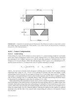
Hopkins et al. (1999) experimentally determined the maximum heat load for various operating tempera-
tures of copper–water micro heat pipes.These micro heat pipes consisted of trapezoidal or rectangular micro
grooves and were positioned in vertical or horizontal orientations. The dry-out condition also was studied
experimentally. The effective thermal resistance was found to decrease with an increase in the heat load.
11.2.2.2 Transient Experimental Investigations
While the model developed by Babin et al. (1990) was shown to predict the steady-state performance limi-
tations and operational characteristics of the trapezoidal heat pipe reasonably well for operating temper-
atures between 40 and 60°C, little was known about the transient behavior of these devices. As a result,
Wu et al. (1991) undertook an experimental investigation of the devices’ transient characteristics. This
11-18 MEMS: Applications
© 2006 by Taylor & Francis Group, LLC
experimental investigation again utilized micro heat pipe test articles developed by Itoh (1988); however,
this particular test pipe was designed to fit securely under a ceramic chip carrier and had small fins at the
condenser end of the heat pipe for removal of heat by free or forced convection, as shown in Figure 11.3.
Start-up and transient tests were conducted in which the transient response characteristics of the heat pipe
as a function of incremental power increases, tilt angle, and mean operating temperature were measured.
Itoh and Polásek (1990a, 1990b), presented the results of an extensive experimental investigation on a
series of micro heat pipes ranging in size and shape from 1 to 3 mm in diameter and 30 to 150mm in length.
The investigation utilized both cross-sectional configurations, similar to those presented previously or a
conventional internal wicking structure (Polásek, 1990; Fejfar et al., 1990). The unique aspect of this par-
ticular investigation was the use of neutron radiography to determine the distribution of the working fluid
within the heat pipes [Itoh and Polásek, 1990a; Itoh and Polásek, 1990b; Ikeda, 1990]. Using this tech-
nique, the amount and distribution of the working fluid and noncondensale gases were observed during
real time operation along with the boiling and/or reflux flow behavior. The results of these tests indicated
several important results [Peterson, 1992];
●
As is the case for conventional heat pipes, the maximum heat transport capacity is principally
dependent upon the mean adiabatic vapor temperature.
●
Micro heat pipes with smooth inner surfaces were found to be more sensitive to overheating than
those with grooved capillary systems.
●
The wall thickness of the individual micro heat pipes had greater effect on the thermal performance
than did the casing material.
●
The maximum transport capacity of heat pipes utilizing axial channels for return of the liquid to
the evaporator were found to be superior to those utilizing a formal wicking structure.
The experimental work on the micro heat pipe array fabricated in silicon using vapor deposition tech-
nique [Mallik and Peterson, 1995] was extended to also include the performance under transient condi-
tions. The results of this study were presented in Peterson and Mallik (1995).
11.3 Arrays of Micro Heat Pipes
Apart from theoretical and experimental research on individual micro heat pipes, modeling, fabrication,
and testing of micro heat pipe arrays of various designs also have been undertaken. Significant work on
these subjects is presented in the following sections.
11.3.1 Modeling of Heat Pipe Arrays
The initial conceptualization of micro heat pipes by Cotter (1984) envisioned fabricating micro heat pipes
directly into the semiconductor devices as shown schematically in Figure 11.6.While many of the previously
discussed models can be used to predict the performance limitations and operational characteristics of indi-
vidual micro heat pipes, it is not clear from the models or analyses how the incorporation of an array of these
devices might affect the temperature distribution or the resulting thermal performance. Mallik et al. (1991)
Micro Heat Pipes and Micro Heat Spreaders 11-19
x
y
z
FIGURE 11.6 Array of micro heat pipes fabricated as an integral part of a silicon wafer.
© 2006 by Taylor & Francis Group, LLC
developed a three-dimensional numerical model capable of predicting the thermal performance of an array
of parallel micro heat pipes constructed as an integral part of semiconductor chips similar to that illustrated
in Figure 11.7. In order to determine the potential advantages of this concept, several different thermal
loading configurations were modeled and the reductions in the maximum surface temperature, the mean
chip temperature,and the maximum temperature gradient across the chip were determined [Peterson, 1994].
Although the previous investigations of Babin et al. (1990), Wu and Peterson (1991), and Wu et al. (1991)
indicated that an effective thermal conductivity greater than ten times that of silicon could be achieved, addi-
tional analyses were conducted to determine the effect of variations in this value. Steady-state analyses were
performed using a heat pipe array comprised of nineteen parallel heat pipes. Using an effective thermal con-
ductivity ratio of five, the maximum and mean surface temperatures were 37.69°C and 4.91°C respectively.
With an effective thermal conductivity ratio of ten, the maximum and mean surface temperatures were
35.20°C and 4.21°C respectively. Using an effective thermal conductivity ratio of fifteen, the maximum and
mean surface temperatures were 32.67°C and 3.64°C respectively [Peterson,1994].These results illustrate how
the incorporation of an array of micro heat pipes can reduce the maximum wafer temperature, reduce the
temperature gradient across the wafers, and eliminate localized hot spots. In addition, this work high-
lighted the significance of incorporating these devices into semiconductor chips, particularly those con-
structed in materials with thermal conductivities significantly less than that of silicon,such as gallium arsenide.
This work was further extended to determine transient response characteristics of an array of micro heat
pipes fabricated into silicon wafers as a substitute for polycrystalline diamond or other highly thermally
conductive heat spreader materials [Mallik and Peterson 1991; Mallik et al. 1992]. The resulting transient
three-dimensional numerical model was capable of predicting the time dependent temperature distribu-
tion occurring within the wafer when given the physical parameters of the wafer and the locations of the
heat sources and sinks. The model also indicated that significant reductions in the maximum localized wafer
temperatures and thermal gradients across the wafer could be obtained through the incorporation of an
array of micro heat pipes. Utilizing heat sinks located on the edges of the chip perpendicular to the axis of
the heat pipes and a cross-sectional area porosity of 1.85%, reductions in the maximum chip temperature
of up to 40% were predicted.
11-20 MEMS: Applications
FIGURE 11.7 (See color insert following page 2-12.)Silicon wafer into which an array of micro heat pipes has been
fabricated.
© 2006 by Taylor & Francis Group, LLC
11.3.2 Testing of Arrays of Micro Heat Pipes
Peterson et al. (1991) fabricated, charged, and tested micro heat pipe arrays incorporated as an integral part of
semiconductor wafers. These tests represented the first successful operation of these devices reported in the
open literature. In this investigation, several silicon wafers were fabricated with distributed heat sources on
one side and an array of micro heat pipes on the other as illustrated in Figure 11.7.Since that time, anumber
of experimental investigations have been conducted to verify the micro heat pipe array concept and determine
the potential advantages of constructing an array of micro heat pipes as an integral part of semiconductor
devices [Peterson et al. 1993; Peterson 1994]. The arrays tested have typically been fabricated in silicon and
have ranged in size from parallel rectangular channels 30 µm wide,80µm deep,and 19.75 mm long,machined
into a silicon wafer 20mm square and 0.378 mm thick with an interchannel spacing of 500µm to etched arrays
of triangular channels 120 µm wide and 80 µm deep machined into 20 mm square silicon wafers 0.5 mm
thick [Peterson et al. 1993]. In addition, arrays of micro heat pipes fabricated using a vapor deposition
process first proposed by Peterson (1990) and illustrated in Figure 11.8 were tested by Mallik et al. (1995).
In this work, wafers with arrays of 34 and 66 micro heat pipes were evaluated using an IR thermal
imaging system in conjunction with a VHS video recorder. These arrays occupied 0.75% and 1.45% of
the wafer cross-sectional area respectively. The wafers with micro heat pipe arrays demonstrated a 30%
to 45% reduction in the thermal time constant when compared to that obtained for plain silicon wafers,
which led to a significant reduction in the maximum wafer temperature. The experimental results were
then used to validate the transient numerical model described previously [Peterson and Mallik, 1995].
11.3.3 Fabrication of Arrays of Micro Heat Pipes
Considerable information is available on the methods used to fabricate micro heat pipes with hydraulic
diameters on the order of 20 to 150 µm in diameter into silicon or gallium arsenide wafers. These early inves-
tigations included the use of conventional techniques such as the machining of small channels [Peterson,
1988b; Peterson et al., 1991]; the use of directionally dependent etching processes to create rectangular or
triangular shaped channels [Peterson, 1988b; Gerner, 1990; Mallik et al., 1991; Gerner et al., 1992]; or other
more elaborate techniques that utilize a multisource vapor deposition process illustrated in Figure 11.8
[Mallik et al., 1991; Weichold et al., 1992] to create an array of long narrow channels of triangular
cross-section lined with a thin layer of copper. Peterson (1994) has summarized these. The earliest fabricated
Micro Heat Pipes and Micro Heat Spreaders 11-21
Metallic layer
Square grooves
Step 3
Seal ends and charge
Step 2
Vapor deposit metallic layer
Silicon
Step 1
Machine square grooves
Construction process
FIGURE 11.8 Vapor deposition process for fabricating micro heat pipes.
© 2006 by Taylor & Francis Group, LLC
arrays were machined into a silicon wafer 2 cm square and 0.378 mm thick, with an interchannel spacing
of 500 µm. Somewhat later, Adkins et al. (1994) reported on a different fabrication process used for an
array of heat pipes with a segmented vapor space. Peterson (1988b), Gerner (1990), Peterson et al. (1993),
Ramadas et al. (1993), and Gerner et al. (1994) have described other processes. All of these techniques were
similar in nature and typically utilized conventional photolithography masking techniques coupled with
an orientation dependent etching technique.
Perhaps the most important aspects of these devices are the shape and relative areas of the liquid and
vapor passages. A number of investigations have been directed at the optimization of these grooves. These
include investigations by Ha and Peterson (1994), which analytically evaluated the axial dry-out of the
evaporating thin liquid film; one by Ha and Peterson (1996), which evaluated the interline heat transfer; and
others that examined other important aspects of the problem [Ha and Peterson 1998a, 1998b; Peterson
and Ha, 1998; Ma and Peterson 1998]. These studies and others have shown both individual micro heat pipes
and arrays of micro heat pipes to be extremely sensitive to flooding [Peterson, 1992]. For this reason, several
different charging methods have been developed and described in detail [Duncan and Peterson, 1995].
These vary from those that are similar to the methods utilized on larger more conventional heat pipes to
one in which the working fluid is added and then the wafer is heated to above the critical temperature of
the working fluid so that the working fluid is in the supercritical state and exists entirely as a vapor. The
array is then sealed and allowed to cool to below the critical temperature, allowing the vapor to cool and
condense. When in the critical state, the working fluid is uniformly distributed throughout the individ-
ual micro heat pipes, so the exact charge can be carefully controlled and calculated.
11.3.4 Wire Bonded Micro Heat Pipe Arrays
One of the designs that has been developed and evaluated for use in both conventional electronic appli-
cations and for advanced spacecraft applications consists of a flexible micro heat pipe array fabricated by
sintering an array of aluminum wires between two thin aluminum sheets as shown in Figure 11.9.In this
design, the sharp corner regions formed by the junction of the plate and the wires act as the liquid arteries.
When made of aluminum with ammonia or acetone as the working fluid, these devices become excellent
candidates for use as flexible radiator panels for long-term spacecraft missions, and they can have a ther-
mal conductivity that greatly exceeds the conductivity of an equivalent thickness of any known material.
A numerical model combining both conduction and radiation effects to predict the heat transfer per-
formance and temperature distribution of these types of radiator fins in a simulated space environment has
been developed [Wang et al., 2001]. Three different configurations were analyzed, experimentally evaluated,
and the results compared. Each of the three configurations were modeled both with and without a working
fluid charge in order to determine the reduction in the maximum temperature,mean temperature, and tem-
perature gradient on the radiator surface. Table 11.1 lists the physical specifications of the three micro heat
pipe arrays fabricated.Acetone was used as the working fluid in both the modeling effort and also in the actual
experimental tests. The flexible radiator with the array of micro heat pipes was found to have an effective ther-
mal conductivity of more than 20 times that of the uncharged version and 10 times that of a solid material.
The results of the preliminary tests conducted on these configurations are shown in Figure 11.10.As indi-
cated, the heat transport was proportional to the temperature difference between the evaporator and con-
denser; that is, the effective thermal conductivity of the micro heat pipe array was constant with respect to
the temperature. From the temperature difference and heat transport obtained as shown in Figure 11.10,
the effective conductivity was calculated. As illustrated in Figure 11.11, the effective thermal conductivities
of micro heat pipe arrays No. 1, No. 2, and No. 3 were 1446.2W/Km, 521.3 W/Km, and 3023.1W/Km, respec-
tively. For the micro heat pipe arrays without any working fluid, the effective conductivities in the x-direction
were 126.3 W/Km, 113.0 W/Km, and 136.2 W/Km respectively. Comparison of the predicted and experi-
mental results indicated these flexible radiators with the arrays of micro heat pipes have an effective thermal
conductivity of between fifteen and twenty times that of the uncharged version. This results in a more uni-
form temperature distribution that could significantly improve the overall radiation effectiveness, reduce the
overall size, and meet or exceed the baseline design requirements for long-term manned missions to Mars.
11-22 MEMS: Applications
© 2006 by Taylor & Francis Group, LLC
Wang and Peterson (2002a) presented an analysis of wire-bonded micro heat pipe arrays using a one-
dimensional steady state analytical model that incorporated the effects of the liquid–vapor phase interactions
and the variation in the cross-section area. The model was used to predict the heat transfer performance
and optimum design parameters. An experimental facility was fabricated, and tests were conducted to
Micro Heat Pipes and Micro Heat Spreaders 11-23
Wires
Condenser
Al
Av.
a
R
R
Al
Al
Al
a
R
Av.
Al
R
Cross-section
Evaporator
FIGURE 11.9 Flexible wire bonded heat pipe. (Reprinted with permission from Wang, Y., Ma, H.B., and Peterson,
G.P. (2001) “Investigation of the Temperature Distributions on Radiator Fins with Micro Heat Pipes,” AIAA J.
Thermophysics and Heat Transfer 15(1), pp. 42–49.)
TABLE 11.1 Configuration of Micro Heat Pipe. Reprinted with Permission from
[Wang, Y., Ma, H.B., and Peterson, G.P. (2001) “Investigation of the Temperature
Distributions on Radiator Fins with Micro Heat Pipes,” AIAA J. Thermophysics and
Heat Transfer 15(1), pp. 42–49.]
Prototype
No. 1 No. 2 No. 3
Material Aluminum Aluminum Aluminum
Working fluid Acetone Acetone Acetone
Total dimension (mm) 152 ϫ 152.4 152 ϫ 152.4 152 ϫ 152.4
Thickness of sheet (mm) 0.40 0.40 0.40
Diameter of wire (mm) 0.50 0.80 0.50
Number of wires 43 43 95
© 2006 by Taylor & Francis Group, LLC
11-24 MEMS: Applications
0
40
80
120
160
200
240
280
0 5 10 15 20 25 30 35 40 45 50
Power input (W)
Temperature difference (°C)
With working fluid
Without working fluid
FIGURE 11.10 (See color insert following page 2-12.)Temperature difference of micro heat pipe arrays with or with-
out working fluid. (Reprinted with permission from Wang, Y., Ma, H.B., and Peterson, G.P. (2001) “Investigation of the
Temperature Distributions on Radiator Fins with Micro Heat Pipes,” AIAA J. Thermophysics and Heat Transfer 15(1),
pp. 42–49.)
0
500
1000
1500
2000
2500
3000
3500
0 20 40 60 80 100 120 140
Power input (W)
Effective conductivity (W/mK)
Test article No.2 (Exp. average)
Test article No.1
Test article No.3
MHP without working fluid
FIGURE 11.11 (See color insert following page 2-12.) Effective thermal conductivity of micro heat pipe arrays.
(Reprinted with permission from Wang, Y., Ma, H.B., and Peterson, G.P. (2001) “Investigation of the Temperature
Distributions on Radiator Fins with Micro Heat Pipes,” AIAA J. Thermophysics and Heat Transfer 15(1), pp. 42–49.)
© 2006 by Taylor & Francis Group, LLC
verify the concept as well as to validate the proposed model. The results indicated that the maximum heat
transport capacity increased with increases in wire diameter and that the overall value was proportional
to the square of the wire diameter. The numerical model indicated that the maximum heat transport
capacity increased with increases in the wire spacing and predicted the existence of an optimal configu-
ration for the maximum heat transfer capacity. Further optimization studies on a wire-bonded micro
heat pipe radiator in a radiation environment were reported in Wang and Peterson (2002b). A combined
numerical and experimental investigation was performed in order to optimize the heat transfer per-
formance of the radiator. The optimal charge volume was found to decrease with increasing heat flux. The
overall maximum heat transport capacity of the radiator was found to be strongly governed by the spacing
of the wires, the length of the radiator, and the radiation capacity of the radiator surface. The numerical
results were consistent with experimental results, which indicated that the uniformity of the temperature
distribution and the radiation efficiency both increased with increasing wire diameter. Among the speci-
mens tested, the maximum heat transport capacity of 15.2 W was found to exist for radiators utilizing a
wire diameter of 0.635 mm. Comparison of the proposed micro heat pipe radiators with solid conductors
and uncharged versions indicated significant improvements in the temperature uniformity and overall radia-
tion efficiency. Aluminum–acetone systems of wire-bonded micro heat pipes were tested in this study.
A flat heat pipe thermal module for use as a cooling device for mobile computers was analyzed by Peterson
and Wang (2003). It consisted of a wire-bonded heat pipe and a fin structure to dissipate heat. The tem-
perature and heat flux distributions were calculated, and a performance analysis was done using a resis-
tance model. Effects of the wire diameter, mesh number of the wire configuration, and the tilt angle of the
heat pipe on the maximum heat transport capacity were investigated. The effect of the air flow rate on
the thermal resistance and the influence of the operating temperature and air flow velocities on the heat
dissipation capacity were also studied. Larger wire diameters were found to lead to a significant increase
in the maximum heat transport capacity.
11.4 Flat Plate Micro Heat Spreaders
While arrays of micro heat pipes can significantly improve the effective thermal conductivity of silicon wafers
and other conventional heat spreaders, they are of limited value in that they provide heat transfer only along
the axial direction of the individual heat pipes. To overcome this problem, flat plate heat spreaders capable
of distributing heat over a large two-dimensional surface have been proposed by Peterson (1992, 1994). In
this application, a wicking structure is fabricated in silicon multichip module substrates to promote the distri-
bution of the fluid and the vaporization of the working fluid (Figure 11.12). This wick structure is the key ele-
ment in these devices, and several methods for wick manufacture have been considered [Peterson et al. 1996].
In the most comprehensive investigation of these devices to date, a flat plate micro heat pipe similar to that
described by Peterson et al. (1996) was fabricated in silicon multichip module (MCS) substrates 5 mm ϫ
5 mm square [Benson et al. 1996a; Benson et al. 1996b]. These devices, which are illustrated in Figure 11.12,
utilized two separate silicon wafers. On one of the two wafers, the wick pattern was fabricated leaving
a small region around the perimeter of the wafer unpatterned to allow the package to be hermetically
sealed. The other silicon wafer was etched in such a manner that a shallow well was formed corresponding
to the wick area. The two pieces were then wafer bonded together along the seal ring. Upon completion
of the fabrication, the flat plate micro heat pipe was filled through a small laser drilled port located in one
corner of the wafer. Because the entire wicking area was interconnected, the volume of the liquid required to
charge was of sufficient volume that conventional charging techniques could be utilized [Benson et al. 1996].
11.4.1 Modeling of Micro Heat Spreaders
Analytical investigations of the performance of these micro heat spreaders or flat plate heat pipes have been
underway for some time; Benson et al. (1996a), Benson et al. (1996b), and Peterson (1996) have summarized
the results. These investigations have demonstrated that these devices can provide an effective mechanism
for distributing the thermal load in semiconductor devices and reducing the localized hot spots resulting
Micro Heat Pipes and Micro Heat Spreaders 11-25
© 2006 by Taylor & Francis Group, LLC
from active chip sites [Peterson, 1996]. The models indicate that the performance of these devices is excel-
lent. In addition, because these devices can be made from silicon, Kovar, or a wide variety of other materi-
als, an excellent match between the coefficient of thermal expansion (CTE) can be achieved while keeping
the material and fabrication costs very low. A number of different wicking structures have been consi-
dered. Among these are wicks fabricated using a silicon dicing saw (Figure 11.13), wicks fabricated using
conventional anisotropic etching techniques (Figure 11.14), and wicks fabricated using a deep plasma
etching technique (Figure 11.15). Recent modeling has focused on the development of optimized wicking
structures that could be fabricated directly into the wafer and provide maximum capillary pumping while
optimizing the thin film region of the meniscus in order to maximize the heat flux [Wayner et al. 1976;
Peterson and Ma, 1996b, 1999; Peterson and Ma 1999].
11-26 MEMS: Applications
Laser drilled
fill port
Chemically
etched vapor
well (bottom
surface)
Glass
bond
area
Wick surface
Silicon wafers
4.8 × 4.8 cm
0.065 cm thick
FIGURE 11.12 Flat plate micro heat spreader. (Reprinted with permission from Benson, D.A., Mitchell, R.T., Tuck,
M.R., Adkins, D.R., and Palmer, D.W. (1996a) “Micro-machined Heat Pipes in Silicon MCM Substrates,” Proc. IEEE
Multichip Module Conference, 6–7 February, Santa Cruz, CA.)
FIGURE 11.13 Wick pattern prepared with bidirectional saw cuts on a silicon wafer. (Reprinted with permission
from Benson, D.A., Mitchell, R.T., Tuck, M.R., Adkins, D.R., and Palmer, D.W. (1996a) “Micro-machined Heat Pipes
in Silicon MCM Substrates,” Proc. IEEE Multichip Module Conference, 6–7 February, Santa Cruz, CA.)
© 2006 by Taylor & Francis Group, LLC
Micro Heat Pipes and Micro Heat Spreaders 11-27
FIGURE 11.14 Chemically etched orthogonal, triangular groove wick. (Reprinted with permission from Mallik, A.K.,
and Peterson, G.P. [1991] “On the Use of Micro Heat Pipes as an Integral Part of Semiconductors,” 3rd ASME-JSME
Thermal Engineering Joint Conference Proc., vol. 2, pp. 394–401, March 17–22, Reno, Nevada.)
FIGURE 11.15 Wick pattern on silicon prepared by a photomask and deep plasma etch technique. Wick features are
25 microns wide and 50 microns deep wafer. (Reprinted with permission from Benson, D.A., Mitchell, R.T., Tuck,
M.R., Adkins, D.R., and Palmer, D.W. (1996a) “Micro-machined Heat Pipes in Silicon MCM Substrates,” Proc. IEEE
Multichip Module Conference, 6–7 February, Santa Cruz, CA.)
The results of these optimization efforts have demonstrated that these micro scale flat plate heat
spreaders allow the heat to be dissipated in any direction across the wafer surface, thereby vastly improv-
ing performance. The resulting effective thermal conductivities can approach and perhaps exceed that of
diamond coatings of equivalent thicknesses. Table 11.2 [Benson et al. 1998] illustrates the relative com-
parison of these flat plate heat pipes and other types of materials traditionally utilized in the electronics
industry for heat spreading. In this comparison, it is important to note that the ideal heat spreader would
have the thermal conductivity of diamond, a coefficient of thermal expansion of silicon, and a cost com-
parable to aluminum. As shown, flat plate heat pipes fabricated in either silicon or Kovar compare very
favorably with diamond in terms of thermal conductivity, have a close coefficient of thermal expansion
of silicon relatively (or exactly in the case of silicon), and a projected cost that is quite low. Based upon
this comparison, it would appear that these flat plate heat pipes have tremendous commercial potential.
11.4.2 Testing of Micro Heat Spreaders
As described by Benson et al. (1998) a number of different flat plate micro heat pipe test articles have been
evaluated using an IR camera to determine the spatially resolved temperature distribution. Using this
information and a technique initially described by Peterson (1993) for arrays of micro heat pipes, the
effective thermal conductivity of charged and uncharged flat plate micro heat pipes, a series of micro heat
spreaders were evaluated experimentally. The results indicated that an effective thermal conductivity
© 2006 by Taylor & Francis Group, LLC
between 10 and 20 W/cm-K was possible over a fairly broad temperature range. These values of thermal
conductivity approach that of polycrystalline diamond substrates, or more than five times that of a solid
silicon substrate, even at elevated temperatures (50°C) and power levels (15 W/cm
2
). The cost of such
advanced silicon substrates is estimated at $.60/cm
2
(see Table 11.2). Any other inexpensive material with
a CTE close to that of the chip may also be a potential option for the heat pipe case material. For example,
many alloys in the Fe/Ni/Co family have CTEs closely matching those of semiconductor materials [Benson
et al. 1996].
As noted by Peterson (1992) several aspects of the technology remain to be examined before flat plate micro
heat spreaders can come into widespread use, but it is clear from the results of these early experimental tests
that spreaders such as those discussed here, fabricated as an integral part of silicon chips, present a feasible
alternative cooling scheme that merits serious consideration for a number of heat transfer applications.
11.4.3 Fabrication of Micro Heat Spreaders
The fabrication of these micro heat spreaders is basically just an extension of the methods used by sev-
eral early investigations to fabricate individual micro heat pipes with hydraulic diameters on the order of
20 to 150 µm. As discussed previously, a number of different wicking structures have been utilized. These
wicking structures included Kovar, silicon, or gallium arsenide and employed conventional techniques such
as the machining, directionally dependent etching, plasma etching or multisource vapor deposition processes.
Charging of these devices is somewhat easier than for the individual arrays of micro heat pipes, and while
these devices are still sensitive to undercharge, they can accommodate an overcharge much more readily.
11.5 New Designs
In addition to the designs described above, several new designs are currently being developed and evalu-
ated for use in conventional electronic applications, advanced spacecraft applications, and biomedical
applications. In electronic applications, the function of the heat pipe design may entail collecting heat
from a microprocessor and transporting it to a conventional heat spreader or to a more readily available
heat sink, such as the screen of a laptop computer. In the advanced spacecraft applications, these devices
may be used to fabricate highly flexible radiator fin structures for use on long-term spacecraft missions.
A design currently being investigated consists of an array of flexible micro heat pipes fabricated in a
polymer material; as illustrated in Figure 11.16a.This material is extruded in such a fashion that it has a
series of large rectangular grooves that serve as the actual heat pipes, each approximately 200 microns
11-28 MEMS: Applications
TABLE 11.2 Thermal Conductivity, Coefficient of Thermal Expansion, Cost Estimates, and Scaling Trends of
Current and Potential Substrate Materials. Reprinted with Permission from Benson, D.A., Adkins, D.R.,
Mitchell, R.T., Tuck, M.R., Palmer, D.W., and Peterson, G.P. (1998) “Ultra High Capacity Micro Machined
Heat Spreaders,” Microscale Thermophys. Eng., 2(1), pp. 21–29
Therm. Conduct. CTE Cost Substrate
Materials (W/cm-K) (10
Ϫ6
/K) ($/Square Inch) Scaling with Area Cost Trend
Alumina 0.25 6.7 $0.09 6Љ limit
FR-4 Depends on copper 13.0 $0.07 Constant to 36Љ
A1N 1.00–2.00 4.1 $0.35 6Љ limit
Silicon 1.48 4.7 $1.00 6Љ–10Љ limit
Heat pipe in silicon 8.00 → 20.00(?) 4.7 $3.00 6Љ–10Љ limit
A1 2.37 41.8 $0.0009 Scales as area
Cu 3.98 28.7 $0.0015 Scales as area
Diamond 10.00–20.00 1.0–1.5 $1000.00 Scales as area
2
Kovar 0.13 5.0 $0.027 Scales as area
Heat pipe in Kovar Ͼ8.00 5.0 $0.10 Scales as area
A1SiC 2.00 (at 70%) 7.0 (?) $1.00 Casting size limited
© 2006 by Taylor & Francis Group, LLC
wide. Within each of these micro heat pipes is a series of smaller grooves that serve as the liquid arteries
(see inset). These grooves can be either rectangular or trapezoidal, as shown in Figure 11.16a or Figure
11.16b. In both cases, the material is polypropylene, and the internal dimension of the individual heat
pipes is approximately 200 microns. The smaller grooves within each of the individual heat pipes are
designed to transport the fluid from the evaporator to the condenser.
While only preliminary experimental test data are available, this design appears to hold great promise for
both spacecraft radiator applications and flexible heat spreaders used in earth-based electronic applications.
In order to understand the heat transfer and fluid flow mechanisms in the microwick structures of flexi-
ble micro membrane/thin film heat pipes, experimental and theoretical studies were performed [Wang
and Peterson, 2002c; Wang and Peterson, 2003]. Experimental tests were conducted to evaluate the evapo-
ration heat transfer limit in the polymer microfilm with 26 µm capillary grooves. The experiments indi-
cated that the maximum heat transport capacity decreased significantly as the effective length of the
Micro Heat Pipes and Micro Heat Spreaders 11-29
FIGURE 11.16 Flexible polymer micro heat pipe: (a) rectangular grooves, (b) trapezoidal grooves.
© 2006 by Taylor & Francis Group, LLC
polymer film increased. The experimental observations also indicated that the maximum liquid menis-
cus radius occurred in the microgrooves just prior to dry-out.
An analytical model based on the Darcy law was used to obtain the pressure gradients, and the experi-
mental results were validated. Two models for predicting the maximum heat transport capacity were
developed — one assuming that the liquid fills only the micro grooves, and the other considering flood-
ing of the space above the micro grooves — and the calculated results were compared with experimental
values. It was found that the experimentally determined maximum capillary evaporation heat transfer
agreed better with the second model, which took into account the flooding effect. Figure 11.17 shows the
comparison of the experimental and analytical results.
The analytical model, based on parametric studies, indicated that decreasing the bottom width of trap-
ezoidal grooves very slightly can improve the evaporation heat transfer performance significantly. The
analytical models were also used to determine the optimal half-angle of the groove for the best heat trans-
fer performance.
Investigations of polymer-based flexible micro heat pipes for applications in spacecraft radiators have also
been undertaken [McDaniels and Peterson, 2001]. Building upon the demonstrated effectiveness of micro
heat pipe arrays as heat spreaders in electronics applications, the possibility of use of regions of micro heat
pipe arrays in flexible radiators was tested.Analytical modeling suggested that a lightweight polymeric mate-
rial with imbedded micro heat pipe arrays can meet heat dissipation requirements while contributing less mass
than other flexible materials. The capillary pumping limit was estimated as a function of the operating tem-
perature, using the analytical model, with water and methanol as the working fluid. For water, the maximum
heat transport was found to be 18 mW per channel, at around 160°C, while for methanol it was 2.2mW per
channel at 120°C. It was shown that the obtained radiator capacity in the range 6.0 kW to 12.2 kW, at source
temperatures of 40°C or higher, met or exceeded the dissipation requirements of a reference spacecraft design.
The focus of this investigation consisted of micro heat pipe arrays that were made from a composite of
two layers: an ungrooved metal foil and a grooved polymer film. A low heat bonding between a polymer
coating of the foil and the raised points of the grooved film formed the micro heat pipe channels. The analy-
sis was used to compute the capillary pumping pressure and the dynamic and frictional pressure drops in the
11-30 MEMS: Applications
Methanol, =10 degree
0.0
4.0
8.0
12.0
16.0
20.0
24.0
0 20 40 60 80 100 120 140 160
Length of the film, mm
Exp.
Model 2
Model 1
Q
max
, W
FIGURE 11.17 Comparison of the modeling and experimental results on microchanneled polymer films.(Reprinted with
permission from Wang, Y.X., and Peterson, G.P. (2002c) “Capillary Evaporation in Microchanneled Polymer Films,” paper
no. AIAA-2002-2767, 8th AMSE/AIAA Joint Thermophysics and Heat Transfer Conference, 24–27 June, St. Louis, MO.)
© 2006 by Taylor & Francis Group, LLC
liquid and the vapor. The results showing the variation of the capillary limit with respect to the temperature
for the two working fluids are shown in Figure 11.18. Selected results were used, with Reynolds number as
the criterion, to assess the validity of the model simplifications regarding the liquid and vapor flow
regimes, which assumed laminar flow for liquid and vapor.
Diverse uses for the micro heat pipe and micro heat spreader can be found in biomedical applications.
One such application is in catheters that provide a hyperthermia or hypothermia source for use in the
treatment of tumors and cancers. Two U.S. patents have been granted for micro heat pipe catheters
[Fletcher and Peterson 1990, 1993]. In the first of these, the micro heat pipe catheter enables the hypo-
or hyperthermic treatment of cancerous tumors or other diseased tissue. The heat pipe is about the size
Micro Heat Pipes and Micro Heat Spreaders 11-31
0
4
8
12
16
20
20 60 100 140 180
Temperature,
°
C
Capillary limit, qc, mW
Temperature,
°
C
0.0
0.4
0.8
1.2
1.6
2.0
2.4
0
40 80 120 160
Capillary limit, qc, mW
(a)
(b)
FIGURE 11.18 (a) Capillary limitation for the polymer micro heat pipe for a single channel as a function of tempera-
ture for the contact angle in the range 0–20 deg. Methanol is the working fluid. (b) Capillary limitation for the poly-
mer micro heat pipe for a single channel as a function of temperature for the contact angle in the range 0–20 deg. With
water as the working fluid.
© 2006 by Taylor & Francis Group, LLC
of a hypodermic needle, and is thermally insulated along a substantial portion of its length. The heat pipe
includes a channel that is partially charged with an appropriate working fluid. The device provides the deliv-
ery or removal of thermal energy directly to or from the tumor or diseased tissue site. In a second design,
the catheter uses a variety of passive heat pipe structures alone or in combination with feedback devices.
This catheter is particularly useful in treating diseased tissue that cannot be removed by surgery, such as
a brain tumor. Another biomedical application under development is the polymer-based micro heat pipe
heat spreader, which is being proposed for the treatment of neocortical seizures by implanting a device that
can provide localized cooling.
11.6 Summary and Conclusions
It is clear from the preceding review that the concept of using micro scale heat pipes and/or flat plate micro
heat pipe heat spreaders is feasible, practical, and cost effective. A number of different concepts and sizes
have been shown to be acceptable from both an experimental and theoretical perspective, and a number
of these devices are already in widespread use. Steady-state and transient models have been developed and
verified experimentally and are capable of predicting the operational limits and performance character-
istics of micro heat pipes with diameters less than 100 microns with a high degree of reliability. These
models are currently being expanded for use in both individual heat pipes and arrays of heat pipes con-
structed as an integral part of semiconductor devices.
In addition to the analytical work, experimental evaluation has indicated that these devices can be effec-
tive in dissipating and transporting heat from localized heat sources and are presently being used in a num-
ber of commercial applications.Arrays of micro heat pipes on the order of 35 microns have been successfully
fabricated, charged, tested, and incorporated as an integral part of semiconductor devices. Extensive test-
ing has indicated that these heat pipes can provide an effective method for dissipating localized heat fluxes,
eliminating localized hot spots, reducing the maximum wafer temperatures, and thereby improving the
wafer reliability.
Finally, several new designs have been and continue to be developed with uses ranging from spacecraft
radiator applications to land-based electronics applications. These new designs incorporate optimized
wicking structures and clever new fabrication schemes along with materials not previously utilized for
heat pipe applications.
Nomenclature
A ϭ area, m
2
C ϭ constant, defined in text, specific heat, J/kg K
d ϭ diameter, m, side of the triangular channel, m
D
H
ϭ hydraulic mean diameter of the channel, m
E ϭ total energy per unit volume, J/m
3
[E ϭ ρ(CT ϩ ½u
2
)]
f ϭ drag coefficient, dimensionless
h
fg
ϭ latent heat of vaporization, J/kg
h
o
ϭ heat transfer coefficient at the condenser, W/m
2
K
k ϭ thermal conductivity, W/m K
k* ϭ thermal conductivity ratio with respect to copper
K ϭ wick permeability, m
2
L ϭ length, length of the heat pipe, m
Ma ϭ Mach number, dimensionless
P ϭ pressure, Pa
q ϭ heat flow rate, W
q
in
ϭ heat flux into the heat sink, W/m
2
R ϭ thermal resistance, K/W; or universal gas constant, J/kg-K
Re ϭ Reynolds number, dimensionless
11-32 MEMS: Applications
© 2006 by Taylor & Francis Group, LLC
r ϭ radius, radius of curvature of the meniscus, m
r
o
ϭ initial radius of curvature of the meniscus, m
t ϭ time, s
T ϭ temperature, K
∆T ϭ temperature difference, T Ϫ T
amb
, K
u ϭ axial velocity, m/s
V ϭ velocity, m/s
w ϭ groove width, m; or wire spacing, m
We ϭ Weber number, dimensionless
x ϭ axial co-ordinate
Greek Symbols
β
ϭ geometric area coefficient in the micro heat pipe model
λ
ϭ latent heat of vaporization, J/kg
µ
ϭ dynamic viscosity, kg/m-s
ρ
ϭ density, kg/m
3
σ
ϭ surface tension, N/m
τ
ϭ shear stress, N/m
2
ψ
ϭ angle of inclination, degrees or radians
Subscripts
amb ϭ ambient
b ϭ boiling
c ϭ capillary, capillary limitation, condenser, cross section
e ϭ entrainment, evaporator section
eff ϭ effective
f ϭ fin
h ϭ hydraulic
i ϭ inner, interface
l ϭ liquid
li ϭ liquid-interface
lw ϭ liquid-wall
m ϭ maximum
o ϭ outer
p ϭ pipe
s ϭ sonic
sat ϭ saturation
v ϭ vapor
vi ϭ vapor-interface
vw ϭ vapor-wall
w ϭ wire spacing, wick
Ϫ ϭ axial hydrostatic pressure
ϩ ϭ normal hydrostatic pressure
References
Adkins, D.R., Shen, D.S., Palmer, D.W., and Tuck, M.R., (1994) “Silicon Heat Pipes for Cooling Electronics,”
Proc. 1st Annual Spacecraft Thermal Control Symp., November 16–18, Albuquerque, NM.
Anon. (1989) “Application of Micro Heat Pipes in Hyperthermia,” Annual Report of the Itoh Research
and Development Laboratory, Osaka.
Micro Heat Pipes and Micro Heat Spreaders 11-33
© 2006 by Taylor & Francis Group, LLC
Babin, B.R., and Peterson, G.P. (1990) “Experimental Investigation of a Flexible Bellows Heat Pipe for
Cooling Discrete Heat Sources,” ASME J. Heat Transfer, 112, pp. 602–7.
Babin, B.R., Peterson, G.P., and Wu, D. (1990) “Steady-State Modeling and Testing of a Micro Heat Pipe,”
ASME J. Heat Transfer, 112, pp. 595–601.
Badran, B., Albayyari, J.M., Gerner, F.M., Ramadas, P., Henderson, H.T., and Baker, K.W. (1993) “Liquid
Metal Micro Heat Pipes,” 29th National Heat Transfer Conference, HTD, Vol. 236, pp. 71–85,
August, 8–11, Atlanta, Georgia.
Benson, D.A., Mitchell, R.T., Tuck, M.R., Adkins, D.R., and Palmer, D.W. (1996a) “Micro-Machined Heat
Pipes in Silicon MCM Substrates,” Proc. IEEE Multichip Module Conference, pp. 127–29, February,
6–7, Santa Cruz, CA.
Benson, D.A., Adkins, D.R., Peterson, G.P., Mitchell, R.T., Tuck, M.R., and Palmer, D.W. (1996b) “Turning
Silicon Substrates into Diamond: Micromachining Heat Pipes,” Advances in Design, Materials, and
Processes for Thermal Spreaders and Heat Sinks Workshop, April 19–21, Vail, CO.
Benson, D.A., Adkins, D.R., Mitchell, R.T., Tuck, M.R., Palmer, D.W., and Peterson, G.P. (1998) “Ultra
High Capacity Micro Machined Heat Spreaders,” Microscale Thermophys. Eng., 2, pp. 21–29.
Camarda, C.J., Rummler, D.R., and Peterson, G.P. (1997) “Multi Heat Pipe Panels,” NASA Tech Briefs,
LAR-14150.
Cao, Y, Faghri, A., and Mahefkey, E.T. (1993) “Micro/Miniature Heat Pipes and Operating Limitations,”
Heat Pipes and Capillary Pumped Loops, ASME HTD, 236, pp. 55–62.
Chen, H., Groll, M., and Rosler, H. (1992) “Micro Heat Pipe: Experimental Investigation and Theoretical
Modeling,” Proc. 8th Int’l. Heat Pipe Conf., pp. 396–400, 14–18 September, Beijing.
Chi, S.W. (1976) Heat Pipe Theory and Practice, McGraw-Hill, New York.
Collier, J.G. (1981) Convective Boiling and Condensation, McGraw-Hill, New York.
Colwell, G.T., and Chang, W.S. (1984) “Measurements of the Transient Behavior of a Capillary Structure
Under Heavy Thermal Loading,” Int. J. Heat Mass Transfer, 27, pp. 541–51.
Cotter, T.P. (1984) “Principles and Prospects of Micro Heat Pipes,” Proc. 5th Int. Heat Pipe Conf.,
pp. 328–35, 14–17 May, Tsukuba, Japan.
Duncan, A.B., and Peterson, G.P. (1995) “Charge Optimization of Triangular Shaped Micro Heat Pipes,”
AIAA J. Thermophys. Heat Transfer, 9, pp. 365–67.
Dunn, P.D., and Reay, D.A. (1982) Heat Pipes, 3rd ed., Pergamon Press, New York.
Faghri, A. (1995) Heat Pipe Science and Technology, Taylor and Francis, Washington, DC.
Faghri, A. (2001) “Advances and Challenges in Micro/Miniature Heat Pipes,” Ann. Rev. Heat Transfer,
12, pp. 1–26.
Fejfar, K., Polásek, F., and Stulc, P. (1990) “Tests of Micro Heat Pipes,” Ann. Report of the SVÚSS, Prague.
Fletcher, L.S., and Peterson, G.P. (1993) “A Micro Heat Pipe Catheter for Local Tumor Hyperthermia,”
U.S. Patent No. 5,190,539.
Garimella, S.V., and Sobhan, C.B. (2001) “Recent Advances in the Modeling and Applications of
Nonconventional Heat Pipes,” Adv. Heat Transfer, 35, pp. 249–308.
Gerner, F.M. (1990) “Micro Heat Pipes,” AFSOR Final Report No. S-210-10MG-066, Wright-Patterson
AFB, Dayton, Ohio.
Gerner, F.M., Badran, B., Henderson, H.T., and Ramadas, P. (1994) “Silicon-Water Micro Heat Pipes,”
Therm. Sci. Eng., 2, pp. 90–97.
Gerner, F.M., Longtin, J.P., Ramadas, P., Henderson, T.H., and Chang, W.S. (1992) “Flow and Heat
Transfer Limitations in Micro Heat Pipes,” 28th National Heat Transfer Conference, San Diego, Ca.,
pp. 99–104, August 9–12.
Ha, J.M., and Peterson, G.P. (1994) “Analytical Prediction of the Axial Dryout of an Evaporating Liquid
Film in Triangular Micro Channels,” ASME J. Heat Transfer, 116, pp. 498–503.
Ha, J.M., and Peterson, G.P. (1996) “The Interline Heat Transfer of Evaporating Thin Films along a Micro
Grooved Surface,” ASME J. Heat Transfer, 118, pp. 747–55.
Ha, J.M., and Peterson, G.P. (1998a) “Capillary Performance of Evaporating Flow in Micro Grooves: An
Analytical Approach for Very Small Tilt Angles,” ASME J. Heat Transfer, 120, pp. 452–57.
11-34 MEMS: Applications
© 2006 by Taylor & Francis Group, LLC
Ha, J.M., and Peterson, G.P. (1998b) “The Heat Transport Capacity of Micro Heat Pipes,” ASME J. Heat
Transfer, 120, pp. 1064–71.
Hopkins, R., Faghri, A., and Khrustalev, D. (1999) “Flat Miniature Heat Pipes with Micro Capillary
Grooves,” ASME J. Heat Transfer, 121, pp. 102–9.
Ikeda, Y. (1990) “Neutron Radiography Tests of Itoh’s Micro Heat Pipes,” private communications of the
Nagoya University to F. Polásek.
Itoh, A. (1988) “Micro Heat Pipes,” Prospectus of the Itoh R and D Laboratory, Osaka.
Itoh, A., and Polásek, F. (1990a) “Development and Application of Micro Heat Pipes,” Proc. 7th
International Heat Pipe Conf., pp. 93–110, May 21–25, Minsk, USSR.
Itoh, A., and Polásek, F. (1990b) “Micro Heat Pipes and Their Application in Industry,” Proc. of the
Czechoslovak-Japanese Symposium on Heat Pipes, Rícany, Czechoslovakia.
Kendall, D.L. (1979) “Vertical Etching of Silicon at Very High Aspect Ratios,” Ann. Rev. Mater. Sci.,
pp. 373–403.
Khrustalev, D., and Faghri, A. (1994) “Thermal Analysis of a Micro Heat Pipe,” ASME J. Heat Transfer,
116, vol. 9, pp. 189–98.
Longtin, J.P., Badran, B., and Gerner, F.M. (1994) “A One-Dimensional Model of a Micro Heat Pipe
During Steady-State Operation,” ASME J. Heat Transfer, 116, pp. 709–15.
Ma, H.B., Peterson, G.P., and Lu, X.J. (1994) “The Influence of the Vapor–Liquid Interactions on the Liquid
Pressure Drop in Triangular Microgrooves,” Int. J. Heat Mass Transfer, 37, pp. 2211–19.
Ma, H.B., Peterson, G.P., and Peng, X.F. (1996) “Experimental Investigation of Countercurrent Liquid–Vapor
Interactions and its Effect on the Friction Factor,” Exp. Therm. Fluid Sci., 12, pp. 25–32.
Ma, H.B., and Peterson, G.P. (1996a) “Experimental Investigation of the Maximum Heat Transport in
Triangular Grooves,” ASME J. Heat Transfer, 118, pp. 740–46.
Ma, H.B., and Peterson, G.P. (1996b) “Temperature Variation and Heat Transfer in Triangular Grooves
with an Evaporating Film,” AIAA J. Thermophys. Heat Transfer, 11, pp. 90–98.
Ma, H.B., and Peterson, G.P. (1998) “Disjoining Pressure Effect on the Wetting Characteristics in a
Capillary Tube,” Microscale Thermophys. Eng., 2, pp. 283–97
Mallik, A.K., and Peterson, G.P. (1991) “On the Use of Micro Heat Pipes as an Integral Part of
Semiconductors,” 3rd ASME-JSME Thermal Engineering Joint Conference Proc., vol. 2, pp. 394–401,
March 17–22, Reno, Nevada.
Mallik, A.K., and Peterson, G.P. (1995) “Steady-State Investigation of Vapor Deposited Micro Heat Pipe
Arrays,” ASME J. Electron. Packag., 117, pp. 75–81.
Mallik, A.K., Peterson, G.P., and Weichold, M.H. (1991) “Construction Processes for Vapor Deposited
Micro Heat Pipes,” 10th Symp. on Electronic Materials Processing and Characteristics, June 3–4, 1991,
Richardson, TX.
Mallik, A.K., Peterson, G.P., and Weichold, M.H. (1992) “On the Use of Micro Heat Pipes as an Integral
Part of Semiconductor Devices,” ASME J. Electron. Packaging, 114, pp. 436–42.
Mallik, A.K., Peterson, G.P., and Weichold, M.H. (1995) “Fabrication of Vapor Deposited Micro Heat Pipes
Arrays as an Integral Part of Semiconductor Devices,”ASME J. Micromech. Syst., 4, pp. 119–31.
Marto, P.J., and Peterson, G.P. (1988) “Application of Heat Pipes to Electronics Cooling,” in Advances in
Thermal Modeling of Electronic Components and Systems, chapter 4, pp. 283–336, Bar-Cohen, A.,
and Kraus, A. D., eds., Hemisphere Publishing Corporation, New York.
McDaniels, D., and Peterson, G.P. (2001) “Investigation Polymer Based Micro Heat Pipes for Flexible
Spacecraft Radiators,” Proc. ASME Heat Transfer Div., HTD-Vol. 142, New York.
Mrácek, P. (1988) “Application of Micro Heat Pipes to Laser Diode Cooling,” Annual Report of the
VÚMS, Prague, Czechoslovakia.
Peterson, G.P. (1987a) “Analysis of a Heat Pipe Thermal Switch,” Proc. 6th International Heat Pipe
Conference, vol. 1, pp. 177–83, May 25–28, Grenoble, France.
Peterson, G.P. (1987b) “Heat Removal Key to Shrinking Avionics,” Aerosp. Am., 8, no. 10, pp. 20–22.
Peterson, G.P. (1988a) “Investigation of Miniature Heat Pipes,” Final Report, Wright Patterson AFB,
Contract No. F33615-86-C-2733, Task 9.
Micro Heat Pipes and Micro Heat Spreaders 11-35
© 2006 by Taylor & Francis Group, LLC