Where.Am.I-Sensors.and.methods.for.mobile.robot.positioning.-.Borenstein(2001) Part 6 pot
Bạn đang xem bản rút gọn của tài liệu. Xem và tải ngay bản đầy đủ của tài liệu tại đây (1.65 MB, 20 trang )
ECHO
BLANKING (INT)
BINH
TRANSMIT (INT)
BLNK
INIT
16 Pulses
Chapter 4: Sensors for Map-Based Positioning 101
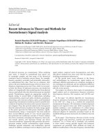
Figure 4.6: Timing diagram for the 6500-
Series Sonar Ranging Module
executing a
multiple-echo-mode cycle with blanking input. (Courtesy of Polaroid Corp.)
For multiple-echo processing, the blanking (BLNK) input must be toggled high for at least 0.44
milliseconds after detection of the first return signal to reset the echo output for the next return.
4.1.2 Laser-Based TOF Systems
Laser-based TOF ranging systems, also known as laser radar or lidar, first appeared in work
performed at the Jet Propulsion Laboratory, Pasadena, CA, in the 1970s [Lewis and Johnson, 1977].
Laser energy is emitted in a rapid sequence of short bursts aimed directly at the object being ranged.
The time required for a given pulse to reflect off the object and return is measured and used to
calculate distance to the target based on the speed of light. Accuracies for early sensors of this type
could approach a few centimeters over the range of 1 to 5 meters (3.3 to 16.4 ft) [NASA, 1977;
Depkovich and Wolfe, 1984].
4.1.2.1 Schwartz Electro-Optics Laser Rangefinders
Schwartz Electro-Optics, Inc. (SEO), Orlando, FL, produces a number of laser TOF rangefinding
systems employing an innovative time-to-amplitude-conversion scheme to overcome the sub-
nanosecond timing requirements necessitated by the speed of light. As the laser fires, a precision
capacitor begins discharging from a known set point at a constant rate. An analog-to-digital
conversion is performed on the sampled capacitor voltage at the precise instant a return signal is
detected, whereupon the resulting digital representation is converted to range using a look-up table.
SEO LRF-200 OEM Laser Rangefinders
The LRF-200 OEM Laser Rangefinder shown in Figure 4.7 features compact size, high-speed
processing, and the ability to acquire range information from most surfaces (i.e., minimum 10-
percent Lambertian reflectivity) out to a maximum of 100 meters (328 ft). The basic system uses a
pulsed InGaAs laser diode in conjunction with an avalanche photodiode detector, and is available
with both analog and digital (RS-232) outputs. Table 4.3 lists general specifications for the sensor's
performance [SEO, 1995a].
102 Part I Sensors for Mobile Robot Positioning
Parameter Value Units
Range (non-cooperative
target)
1 to 100
3.3-328
m
ft
Accuracy ±30
±12
cm
in
Range jitter ±12
±4.7
cm
in
Wavelength 902 nm
Diameter 89
3.5
mm
in
Length 178
7
mm
in
Weight 1
2.2
kg
lb
Power 8 to 24
5
VDC
W
Table 4.3: Selected specifications for the
LRF 200
OEM Laser Rangefinder
. (Courtesy of Schwartz
Electro-Optics, Inc.)
Parameter Value Units
Range 1-100
3.3-330
m
ft
Accuracy ±30
±12
cm
in
Scan angle ±30
Scan rate 24.5- 30.3 kHz
Samples per scan 175
Wavelength 920 nm
Diameter 127
5
mm
in
Length 444
17.5
mm
in
Weight 5.4
11.8
kg
lb
Power 8-25 VDC
Table 4.4: Selected specifications for the SEO
Scanning Laser Rangefinder
. (Courtesy of Schwartz
Electro-Optics, Inc.)
Figure 4.7: The
LRF-200 OEM Laser Rangefinder.
(Courtesy of Schwartz Electro-Optics,
Inc.)
Another adaptation of the LRF-200 involved the addition of a mechanical single-DOF beam
scanning capability. Originally developed for use in submunition sensor research, the Scanning Laser
Rangefinder is currently installed on board a remotely piloted vehicle. For this application, the
sensor is positioned so the forward motion of the RPV is perpendicular to the vertical scan plane,
since three-dimensional target profiles are required [SEO, 1991b]. In a second application, the
Scanning Laser Rangefinder was used by the Field Robotics Center at Carnegie Mellon University
as a terrain mapping sensor on their unmanned autonomous vehicles.
Chapter 4: Sensors for Map-Based Positioning 103
Figure 4.8: The
Scanning Helicopter Interference
Envelope Laser Detector (SHIELD)
. (Courtesy of
Schwartz Electro-Optics, Inc.)
Parameter Value Units
Maximum range
(hemispherical envelope)
>60
>200
m
ft
Accuracy <30
1
cm
ft
Wavelength 905 nm
Scan angle 360
Scan rate 18 Hz
Length 300
11.75
mm
in
Weight 15 lb
Power 18
<5
VDC
A
Table 4.5: Selected specifications for the
Scanning
Helicopter Interference Envelope Laser Detector
(SHIELD).
(Courtesy of Schwartz Electro-Optics, Inc.)
SEO Scanning Helicopter Interference Envelope Laser Detector (SHIELD)
This system was developed for the U.S. Army [SEO, 1995b] as an onboard pilot alert to the presence
of surrounding obstructions in a 60-meter radius hemispherical envelope below the helicopter. A
high-pulse-repetition-rate GaAs eye-safe diode emitter shares a common aperture with a sensitive
avalanche photodiode detector. The transmit and return beams are reflected from a motor-driven
prism rotating at 18 rps (see Figure 4.9). Range measurements are correlated with the azimuth angle
using an optical encoder. Detected obstacles are displayed on a 5.5-inch color monitor. Table 4.5
lists the key specifications of the SHIELD.
SEO TreeSense
The TreeSense system was developed by SEO for
automating the selective application of pesticides
to orange trees, where the goal was to enable individual spray nozzles only when a tree was detected
within their associated field of coverage. The sensing subsystem (see Figure 4.9) consists of a
horizontally oriented unit mounted on the back of an agricultural vehicle, suitably equipped with a
rotating mirror arrangement that scans the beam in a vertical plane orthogonal to the direction of
travel. The scan rate is controllable up to 40 rps (35 rps typical). The ranging subsystem is gated on
and off twice during each revolution to illuminate two 90-degree fan-shaped sectors to a maximum
range of 7.6 meters (25 ft) either side of the vehicle as shown in Figure 4.10. The existing hardware
is theoretically capable of ranging to 9 meters (30 ft) using a PIN photodiode and can be extended
further through an upgrade option that incorporates an avalanche photodiode detector.
The TreeSense system is hard-wired to a valve manifold to enable/disable a vertical array of
nozzles for the spraying of insecticides, but analog as well as digital (RS-232) output can easily be
made available for other applications. The system is housed in a rugged aluminum enclosure with
a total weight of only 2.2 kilograms (5 lb). Power requirements are 12 W at 12 VDC. Further details
on the system are contained in Table 4.6.
104 Part I Sensors for Mobile Robot Positioning
Figure 4.9: The SEO
TreeSense
. (Courtesy of
Schwartz Electro-Optics, Inc.)
Figure 4.10: Scanning pattern of the SEO
TreeSense
system. (Courtesy of Schwartz Electro-Optics, Inc.)
Parameter Value Units
Maximum range 9
30
m
ft
Accuracy
(in % of measured range)
1%
Wavelength 902 nm
Pulse repetition frequency 15 KHz
Scan rate 29.3 rps
Length 229
9
mm
in
Width 229
9
mm
in
Height 115
4.5
mm
in
Weight 5 lbs
Power 12
12
V
W
Table 4.6: Selected specifications for the
TreeSense
system. (Courtesy of Schwartz Electro-
Optics, Inc.)
Figure 4.11: Color-coded range image created by
the SEO
TreeSense
system. (Courtesy of
Schwartz Electro-Optics, Inc.)
SEO AutoSense
The AutoSense I system was developed by SEO under a Department of Transportation Small
Business Innovative Research (SBIR) effort as a replacement for buried inductive loops for traffic
signal control. (Inductive loops don’t always sense motorcyclists and some of the smaller cars with
fiberglass or plastic body panels, and replacement or maintenance can be expensive as well as
disruptive to traffic flow.) The system is configured to look down at about a 30-degree angle on
moving vehicles in a traffic lane as illustrated in Figure 4.12.
AutoSense I uses a PIN photo-diode detector and a pulsed (8 ns) InGaAs near-infrared laser-diode
source with peak power of 50 W. The laser output is directed by a beam splitter into a pair of
cylindrical lenses to generate two fan-shaped beams 10 degrees apart in elevation for improved
target detection. (The original prototype projected
only a single spot of light, but ran into problems
due to target absorption and specular reflection.)
As an added benefit, the use of two separate beams
makes it possible to calculate the speed of moving
vehicles to an accuracy of 1.6 km/h (1 mph). In
addition, a two-dimensional image (i.e., length and
Chapter 4: Sensors for Map-Based Positioning 105
Figure 4.12: Two fan-shaped beams look down on moving vehicles for improved
target detection. (Courtesy of Schwartz Electro-Optics, Inc.)
Figure 4.13:
The AutoSense II
is SEO's active-infrared overhead vehicle
imaging sensor. (Courtesy of Schwartz Electro-Optics, Inc.)
width) is formed of each vehicle as it passes through the sensor’s field of view, opening the door for
numerous vehicle classification applications under the Intelligent Vehicle Highway Systems concept.
AutoSense II is an improved second-generation unit (see Figure 4.13) that uses an avalanche
photodiode detector instead of the PIN photodiode for greater sensitivity, and a multi-faceted
rotating mirror with alternating pitches on adjacent facets to create the two beams. Each beam is
scanned across the traffic lane 720 times per second, with 15 range measurements made per scan.
This azimuthal scanning action generates a precise three-dimensional profile to better facilitate
vehicle classification in automated toll booth applications. An abbreviated system block diagram is
depicted in Figure 4.14.
amplitude
Time to
converter
processor
Micro-
RS 422
RS 232
Laser
driver
Laser trigger
Lens
Optical
filter
Detector
Scanner
interface
Lens
FO line
diode
Laser
Start
Stop
Peak
detector
Range
gate
Detector
Trigger
circuit
Threshold
detector
Ref
106 Part I Sensors for Mobile Robot Positioning
Figure 4.14:
Simplified block diagram of the
AutoSense II
time-of-flight 3-D ranging system. (Courtesy of
Schwartz Electro-Optics, Inc.)
Parameter Value Units
Range 0.61-1.50
2-50
m
ft
Accuracy 7.5
3
cm
in
Wavelength 904 nm
Pulse repetition rate 86.4 kHz
Scan rate 720 scans/s/scanline
Range readings per scan 30
Weight 11.4
25
kg
lb
Power 115
75
VAC
W
Table 4.7:
Selected specifications for the AutoSense II
ranging system. (Courtesy of Schwartz Electro-Optics,
Inc.)
Figure 4.15:
Output sample from a scan
with the
AutoSense II
.
a. Actual vehicle with trailer (photographed
with a conventional camera).
b. Color-coded range information.
c. Intensity image.
(Courtesy of Schwartz Electro-Optics, Inc.)
Intensity information from the reflected signal is used to correct the “time-walk” error in
threshold detection resulting from varying target reflectivities, for an improved range accuracy of
7.6 cm (3 in) over a 1.5 to 15 m (5 to 50 ft) field of regard. The scan resolution is 1 degree, and
vehicle velocity can be calculated with an accuracy of 3.2 km/h (2 mph) at speeds up to 96 km/h
(60 mph). A typical scan image created with the Autosense II is shown in Figure 4.15.
A third-generation AutoSense III is now under development for an application in Canada that
requires 3-dimensional vehicle profile generation at
speeds up to 160 km/h (100 mph). Selected specifications
for the AutoSense II package are provided in Table 4.7.
Chapter 4: Sensors for Map-Based Positioning 107
Figure 4.16: The RIEGL
LD90-3 series
laser rangefinder. (Courtesy of Riegl
USA.)
4.1.2.2 RIEGL Laser Measurement Systems
RIEGL Laser Measurement Systems, Horn, Austria, offers a number of commercial products (i.e.,
laser binoculars, surveying systems, “speed guns,” level sensors, profile measurement systems, and
tracking laser scanners) employing short-pulse TOF laser ranging. Typical applications include lidar
altimeters, vehicle speed measurement for law enforcement, collision avoidance for cranes and
vehicles, and level sensing in silos. All RIEGL products are distributed in the United States by
RIEGEL USA, Orlando, FL.
LD90-3 Laser Rangefinder
The RIEGL LD90-3 series laser rangefinder (see Figure 4.16) employs a near-infrared laser diode
source and a photodiode detector to perform TOF ranging out to 500 meters (1,640 ft) with diffuse
surfaces, and to over 1,000 meters (3,281 ft) in the case of co-operative targets. Round-trip
propagation time is precisely measured by a quartz-stabilized clock and converted to measured
distance by an internal microprocessor using one of two available algorithms. The clutter suppression
algorithm incorporates a combination of range measurement averaging and noise rejection
techniques to filter out backscatter from airborne particles, and is therefore useful when operating
under conditions of poor visibility [Riegl, 1994]. The standard measurement algorithm, on the other
hand, provides rapid range measurements without regard for noise suppression, and can subsequently
deliver a higher update rate under more favorable environmental conditions. Worst-case range
measurement accuracy is ±5 centimeters (±2 in), with typical values of around ±2 centimeters (±0.8
in). See Table 4.8 for a complete listing of the LD90-3's features.
The pulsed near-infrared laser is Class-1 eye safe under all operating conditions. A nominal beam
divergence of 0.1 degrees (2 mrad) for the LD90-3100 unit (see Tab. 4.9 below) produces a
20 centimeter (8 in) footprint of illumination at 100 meters (328 ft) [Riegl, 1994]. The complete
system is housed in a small light-weight metal enclosure weighing only 1.5 kilograms (3.3 lb), and
draws 10 W at 11 to 18 VDC. The standard output format is serial RS-232 at programmable data
Scan Axis
Receive lens
Transmit lens
Top view
180 mm
36
Front view
100
100
mm
O
108 Part I Sensors for Mobile Robot Positioning
Parameter LD90-3100 LD90-3300 Units
Maximum range (diffuse) 150
492
400
1,312
m
ft
(cooperative) >1000
>3,280
>1000
>3,280
m
ft
Minimum range 1 3-5 m
Accuracy (distance) 2
¾
5
2
cm
in
(velocity) 0.3 0.5 m/s
Beam divergence 2 2.8 mrad
Output (digital) RS-232, -422 RS-232, -422
(analog) 0-10 0-10 VDC
Power 11-18 11-18 VDC
10 10 W
Size 22×13×7.6
8.7×5.1×3
22×13×7.6
8.7×5.1×3
cm
in
Weight 3.3 3.3 lb
Table 4.8: Selected specifications for the RIEGL LD90-3 series laser rangefinder. (Courtesy of RIEGL
Laser Measurement Systems.)
Figure 4.17: The LRS90-3 Laser Radar Scanner consists of an electronics unit (not shown) connected via
a duplex fiber-optic cable to the remote scanner unit depicted above. (Courtesy of RIEGL USA.)
rates up to 19.2 kilobits per second, but RS-422 as well as analog options (0 to 10 VDC and 4 to 20
mA current-loop) are available upon request.
Scanning Laser Rangefinders
The LRS90-3 Laser Radar Scanner is an adaptation of the basic LD90-3 electronics, fiber-optically
coupled to a remote scanner unit as shown in Figure 4.17. The scanner package contains no internal
electronics and is thus very robust under demanding operating conditions typical of industrial or
robotics scenarios. The motorized scanning head pans the beam back and forth in the horizontal plane
at a 10-Hz rate, resulting in 20 data-gathering sweeps per second. Beam divergence is 0.3 degrees
(5 mrad) with the option of expanding in the vertical direction if desired up to 2 degrees.
Chapter 4: Sensors for Map-Based Positioning 109
Parameter LRS90-3 LSS390 Units
Maximum range 80
262
60
197
m
ft
Minimum range 2
6.5
1
3.25
m
ft
Accuracy 3
1.2
10
4
cm
ft
Beam divergence 5 3.5 mrad
Sample rate 1000 2000 Hz
Scan range 18 10
Scan rate 10 10 scans/s
Output (digital) RS-232, -422 parallel, RS-422
Power 11-15 9-16 VDC
880 mA
Size (electronics) 22×13×7.6
8.7×5.1×3
22×13×7.6
8.7×5.1×3
cm
in
(scanner) 18×10×10
7×4×4
18×10×10
7×4×4
cm
in
Weight (electronics) 7.25 2.86 lb
(scanner) 3.52 2 lb
Table 4.9: Typical specifications for the
LRS90-3 Laser Radar Scanner
and the
LSS390 Laser
Scanner System
. (Courtesy of RIEGL USA.)
The LSS390 Laser Scanning System is very similar to the LRS90-3, but scans a more narrow field
of view (10) with a faster update rate (2000 Hz) and a more tightly focused beam. Range accuracy
o
is 10 centimeters (4 in) typically and 20 centimeters (8 in) worst case. The LSS390 unit is available
with an RS-422 digital output (19.2 kbs standard, 150 kbs optional) or a 20 bit parallel TTL interface.
4.1.2.3 RVSI Long Optical Ranging and Detection System
Robotic Vision Systems, Inc., Haupaugue, NY, has conceptually designed a laser-based TOF ranging
system capable of acquiring three-dimensional image data for an entire scene without scanning. The
Long Optical Ranging and Detection System (LORDS) is a patented concept incorporating an optical
encoding technique with ordinary vidicon or solid state camera(s), resulting in precise distance
measurement to multiple targets in a scene illuminated by a single laser pulse. The design
configuration is relatively simple and comparable in size and weight to traditional TOF and phase-
shift measurement laser rangefinders (Figure 4.18).
Major components will include a single laser-energy source; one or more imaging cameras, each
with an electronically implemented shuttering mechanism; and the associated control and processing
electronics. In a typical configuration, the laser will emit a 25-mJ (millijoule) pulse lasting 1
nanosecond, for an effective transmission of 25 mW. The anticipated operational wavelength will
lie between 532 and 830 nanometers, due to the ready availability within this range of the required
laser source and imaging arrays.
The cameras will be two-dimensional CCD arrays spaced closely together with parallel optical
axes resulting in nearly identical, multiple views of the illuminated surface. Lenses for these cameras
will be of the standard photographic varieties between 12 and 135 millimeters. The shuttering
Range gate
CCD array
Timing generator
Cone shaped object
Laser
Range gate 2 (B)
Range gate 3 (C)
Schematic of portion
Illuminated vs time
Schematic of portion
Range gate 1 (A)
received vs time
Object to lens delay
Transmitted pulse
7654321
(delayed)
110 Part I Sensors for Mobile Robot Positioning
Figure 4.18: Simplified block diagram of a three-camera configuration of the
LORDS
3-D laser TOF
rangefinding system. (Courtesy of Robotics Vision Systems, Inc.)
Figure 4.19: Range ambiguity is reduced by increasing the number of binary range gates. (Courtesy of
Robotic Vision Systems, Inc.)
function will be performed by microchannel plate image intensifiers (MCPs) 18 or 25 millimeters in
size, which will be gated in a binary encoding sequence, effectively turning the CCDs on and off
during the detection phase. Control of the system will be handled by a single-board processor based
on the Motorola
MC-68040
.
LORDS
obtains three-dimensional image information in real time by employing a novel time-of-
flight technique requiring only a single laser pulse to collect all the information for an entire scene.
The emitted pulse journeys a finite distance over time; hence, light traveling for 2 milliseconds will
illuminate a scene further away than light traveling only 1 millisecond.
The entire sensing range is divided into discrete distance increments, each representing a distinct
range plane. This is accomplished by simultaneously gating the MCPs of the observation cameras
according to their own unique on-off encoding pattern over the duration of the detection phase. This
binary gating alternately blocks and passes any returning reflection of the laser emission off objects
within the field-of-view. When the gating cycles of each camera are lined up and compared, there
exists a uniquely coded correspondence which can be used to calculate the range to any pixel in the
scene.
Range gate 2Range gate 1
21 34567
Range gate 3 Composite
Chapter 4: Sensors for Map-Based Positioning 111
Figure 4.20:
Binary coded images from range gates 1-3 are combined to generate
the composite range map on the far right. (Courtesy of Robotics Vision Systems, Inc.)
For instance, in a system configured with only one camera, the gating MCP would be cycled on
for half the detection duration, then off the remainder of the time. Figure 4.19 shows any object
detected by this camera must be positioned within the first half of the sensor’s overall range (half
the distance the laser light could travel in the allotted detection time). However, significant distance
ambiguity exists because the exact time of detection of the reflected energy could have occurred
anywhere within this relatively long interval.
This ambiguity can be reduced by a factor of two through the use of a second camera with its
associated gating cycled at twice the rate of the first. This scheme would create two complete
on-off
sequences, one taking place while the first camera is on and the other while the first camera is off.
Simple binary logic can be used to combine the camera outputs and further resolve the range. If the
first camera did not detect an object but the second did, then by examining the instance when the
first camera is off and the second is on, the range to the object can be associated with a relatively
specific time frame. Incorporating a third camera at again twice the gating frequency (i.e., two cycles
for every one of camera two, and four cycles for every one of camera one) provides even more
resolution. As Figure 4.20 shows, for each additional CCD array incorporated into the system, the
number of distance divisions is effectively doubled.
Alternatively, the same encoding effect can be achieved using a single camera when little or no
relative motion exists between the sensor and the target area. In this scenario, the laser is pulsed
multiple times, and the gating frequency for the single camera is sequentially changed at each new
transmission. This creates the same detection intervals as before, but with an increase in the time
required for data acquisition.
LORDS
is designed to operate over distances between one meter and several kilometers. An
important characteristic is the projected ability to range over selective segments of an observed
scene to improve resolution in that the depth of field over which a given number of range increments
is spread can be variable. The entire range of interest is initially observed, resulting in the maximum
distance between increments (coarse resolution). An object detected at this stage is thus localized
to a specific, abbreviated region of the total distance.
The sensor is then electronically reconfigured to cycle only over this region, which significantly
shortens the distance between increments, thereby increasing resolution. A known delay is
introduced between transmission and the time when the detection/gating process is initiated. The
laser light thus travels to the region of interest without concern for objects positioned in the
foreground.
Rx
x
d
n=1 n=2
n=8
Tx
n=7
Liquid
n=3
n=4
Surface
n=5n=6
4 d
112 Part I Sensors for Mobile Robot Positioning
Figure 4.21: Relationship between outgoing and reflected waveforms, where x is the
distance corresponding to the differential phase. (Adapted from [Woodbury et al.,
1993].)
(4.1)
4.2 Phase-Shift Measurement
The phase-shift measurement (or phase-detection) ranging technique involves continuous wave
transmission as opposed to the short pulsed outputs used in TOF systems. A beam of amplitude-
modulated laser, RF, or acoustical energy is directed towards the target. A small portion of this wave
(potentially up to six orders of magnitude less in amplitude) is reflected by the object's surface back
to the detector along a direct path [Chen et al., 1993]. The returned energy is compared to a
simultaneously generated reference that has been split off from the original signal, and the relative
phase shift between the two is measured as illustrated in Figure 4.21 to ascertain the round-trip
distance the wave has traveled. For high-frequency RF- or laser-based systems, detection is usually
preceded by heterodyning the reference and received signals with an intermediate frequency (while
preserving the relative phase shift) to allow the phase detector to operate at a more convenient lower
frequency [Vuylsteke, 1990].
The relative phase shift expressed as a function of distance to the reflecting target surface is
[Woodbury et al., 1993]:
where
= phase shift
d = distance to target
= modulation wavelength.
d
4
c
4 f
lim
T
1
T
T
0
sin
2 c
t
4 d
sin
2 c
dt
V
1
V
2
Phase
V
p
XOR Gate
R
V
C
Figueroa.ds4, .wmf
Acos
4 d
Chapter 4: Sensors for Map-Based Positioning 113
(4.2)
(4.3)
Figure 4.22: At low frequencies typical of ultrasonic
systems, a simple phase-detection circuit based on an
exclusive-or
gate will generate an analog output voltage
proportional to the phase difference seen by the inputs.
(Adapted from [Figueroa and Barbieri, 1991].)
(4.4)
The desired distance to target d as a function of the measured phase shift is therefore given by
where
f = modulation frequency.
For square-wave modulation at the relatively low frequencies typical of ultrasonic systems (20
to 200 kHz), the phase difference between incoming and outgoing waveforms can be measured with
the simple linear circuit shown in Figure 4.22 [Figueroa and Barbieri, 1991]. The output of the
exclusive-or gate goes high whenever its inputs are at opposite logic levels, generating a voltage
across capacitor C that is proportional to the phase shift. For example, when the two signals are in
phase (i.e., = 0), the gate output stays low and V is zero; maximum output voltage occurs when
reaches 180 degrees. While easy to implement, this simplistic approach is limited to low
frequencies, and may require frequent calibration to compensate for drifts and offsets due to
component aging or changes in ambient conditions [Figueroa and Lamancusa, 1992].
At higher frequencies, the phase shift between outgoing and reflected sine waves can be
measured by multiplying the two signals together in an electronic mixer, then averaging the product
over many modulation cycles [Woodbury et al., 1993]. This integration process can be relatively
time consuming, making it difficult to achieve extremely rapid update rates. The result can be
expressed mathematically as follows [Woodbury et al., 1993]:
which reduces to
where
t = time
T = averaging interval
A = amplitude factor from gain of inte-
grating amplifier.
From the earlier expression for , it can
be seen that the quantity actually measured
is in fact the cosine of the phase shift and not the phase shift itself [Woodbury et al., 1993]. This
situation introduces a so-called ambiguity interval for scenarios where the round-trip distance
exceeds the modulation wavelength (i.e., the phase measurement becomes ambiguous once
R
a
c
2f
cos
cos
4 d
cos
2 (x n )
114 Part I Sensors for Mobile Robot Positioning
(4.5)
(4.6)
exceeds 360 ). Conrad and Sampson [1990] define this ambiguity interval as the maximum range
that allows the phase difference to go through one complete cycle of 360 degrees:
where
R = ambiguity range interval
a
f = modulation frequency
c = speed of light.
Referring again to Figure 4.21, it can be seen that the total round-trip distance 2d is equal to some
integer number of wavelengths n plus the fractional wavelength distance x associated with the
phase shift. Since the cosine relationship is not single valued for all of , there will be more than one
distance d corresponding to any given phase shift measurement [Woodbury et al., 1993]:
where:
d = (x + n ) / 2 = true distance to target.
x = distance corresponding to differential phase .
n = number of complete modulation cycles.
The potential for erroneous information as a result of this ambiguity interval reduces the appeal
of phase-detection schemes. Some applications simply avoid such problems by arranging the optical
path so that the maximum possible range is within the ambiguity interval. Alternatively, successive
measurements of the same target using two different modulation frequencies can be performed,
resulting in two equations with two unknowns, allowing both x and n to be uniquely determined. Kerr
[1988] describes such an implementation using modulation frequencies of 6 and 32 MHz.
Advantages of continuous-wave systems over pulsed time-of-flight methods include the ability
to measure the direction and velocity of a moving target in addition to its range. In 1842, an Austrian
by the name of Johann Doppler published a paper describing what has since become known as the
Doppler effect. This well-known mathematical relationship states that the frequency of an energy
wave reflected from an object in motion is a function of the relative velocity between the object and
the observer. This subject was discussed in detail in Chapter 1.
As with TOF rangefinders, the paths of the source and the reflected beam are coaxial for phase-
shift-measurement systems. This characteristic ensures objects cannot cast shadows when
illuminated by the energy source, preventing the missing parts problem. Even greater measurement
accuracy and overall range can be achieved when cooperative targets are attached to the objects of
interest to increase the power density of the return signal.
Sync
Programmable
interface
mechanism
Phaselock
processor
scan
60 FOV
raster
Scan
Adp
Scan unit
diode
laser
Video
Range/
video
processor
Cw
Range
buffer
frame
Electronics unit
Chapter 4: Sensors for Map-Based Positioning 115
Figure 4.23:
Block diagram of the Odetics scanning laser rangefinder. (Courtesy of Odetics, Inc.)
Laser-based continuous-wave (CW) ranging originated out of work performed at the Stanford
Research Institute in the 1970s [Nitzan et al., 1977]. Range accuracies approach those of pulsed
laser TOF methods. Only a slight advantage is gained over pulsed TOF rangefinding, however, since
the time-measurement problem is replaced by the need for fairly sophisticated phase-measurement
electronics [Depkovich and Wolfe, 1984]. Because of the limited information obtainable from a
single range point, laser-based systems are often scanned in one or more directions by either
electromechanical or acousto-optical mechanisms.
4.2.1 Odetics Scanning Laser Imaging System
Odetics, Inc., Anaheim, CA, developed an adaptive and versatile scanning laser rangefinder in the
early 1980s for use on ODEX 1, a six-legged walking robot [Binger and Harris, 1987; Byrd and
DeVries, 1990]. The system determines distance by phase-shift measurement, constructing three-
dimensional range pictures by panning and tilting the sensor across the field of view. The phase-shift
measurement technique was selected over acoustic-ranging, stereo vision and structured light
alternatives because of the inherent accuracy and fast update rate.
The imaging system is broken down into the two major subelements depicted in Figure 4.23: the
scan unit and the electronics unit. The scan unit houses the laser source, the photodetector, and the
scanning mechanism. The laser source is a GaAlAs laser diode emitting at a wavelength of
820 nanometers; the power output is adjustable under software control between 1 to 50 mW.
Detection of the returned energy is achieved through use of an avalanche photodiode whose output
is routed to the phase-measuring electronics.
The scanning hardware consists of a rotating polygonal mirror which pans the laser beam across
the scene, and a planar mirror whose back-and-forth nodding motion tilts the beam for a realizable
field of view of 60 degrees in azimuth and 60 degrees in elevation. The scanning sequence follows
a raster-scan pattern and can illuminate and detect an array of 128×128 pixels at a frame rate of 1.2
Hz [Boltinghouse et al., 1990].
The second subelement, the electronics unit, contains the range calculating and video processor
as well as a programmable frame buffer interface. The range and video processor is responsible for
controlling the laser transmission, activation of the scanning mechanism, detection of the returning
116 Part I Sensors for Mobile Robot Positioning
Parameter Value Units
Accuracy < 6 in
AGC output 1-5 V
Output power 2 mW
Beam width 2.5
1
cm
in
Dimensions 15×15×30
6×6×12
cm
in
Weight lb
Power 12 VDC
2A
Table 4.10: Selected specifications for the LED-
based near-infrared
Optical Ranging System
.
(Courtesy of ESP Technologies, Inc.)
energy, and determination of range values. Distance is calculated through a proprietary phase-
detection scheme, reported to be fast, fully digital, and self-calibrating with a high signal-to-noise
ratio. The minimum observable range is 0.46 meters (1.5 ft), while the maximum range without
ambiguity due to phase shifts greater than 360 degrees is 9.3 meters (30 ft).
For each pixel, the processor outputs a range value and a video reflectance value. The video data
are equivalent to that obtained from a standard black-and-white television camera, except that
interference due to ambient light and shadowing effects are eliminated. The reflectance value is
compared to a prespecified threshold to eliminate pixels with insufficient return intensity to be
properly processed, thereby eliminating potentially invalid range data; range values are set to
maximum for all such pixels [Boltinghouse and Larsen, 1989]. A 3×3 neighborhood median filter
is used to further filter out noise from data qualification, specular reflection, and impulse response
[Larson and Boltinghouse, 1988].
The output format is a 16-bit data word consisting of the range value in either 8 or 9 bits, and the
video information in either 8 or 7 bits, respectively. The resulting range resolution for the system is
3.66 centimeters (1.44 in) for the 8-bit format, and 1.83 centimeters (0.72 in) with 9 bits. A buffer
interface provides interim storage of the data and can execute single-word or whole-block direct-
memory-access transfers to external host controllers under program control. Information can also
be routed directly to a host without being held in the buffer. Currently, the interface is designed to
support VAX, VME-Bus, Multibus, and IBM-PC/AT equipment. The scan and electronics unit
together weigh 31 lb and require 2 A at 28 VDC.
4.2.2 ESP Optical Ranging System
A low-cost near-infrared rangefinder (see Fig. 4.24, Fig. 4.25, and Tab. 4.10) was developed in 1989
by ESP Technologies, Inc., Lawrenceville, NJ [ESP], for use in autonomous robot cart navigation
in factories and similar environments. An eyesafe 2 mW, 820-nanometer LED source is 100 percent
modulated at 5 MHz and used to form a collimated 2.5 centimeters (1 in) diameter transmit beam
that is unconditionally eye-safe. Reflected radiation is focused by a 10-centimeter (4 in) diameter
coaxial Fresnel lens onto the photodetector; the measured phase shift is proportional to the round-
trip distance to the illuminated object. The Optical Ranging System (ORS-1) provides three outputs:
range and angle of the target, and an automatic
gain control (AGC) signal [Miller and Wagner,
1987]. Range resolution at 6.1 meters (20 ft) is
approximately 6 centimeters (2.5 in), while angular
resolution is about 2.5 centimeters (1 in) at a range
of 1.5 meters (5 ft).
The ORS-1 AGC output signal is inversely
proportional to the received signal strength and
provides information about a target’s near-infrared
reflectivity, warning against insufficient or exces-
sive signal return [ESP, 1992]. Usable range results
are produced only when the corresponding gain
signal is within a predetermined operating range. A
rotating mirror mounted at 45 degrees to the
optical axis provides 360-degree polar-coordinate
Light
out
6.0" max.
Detector
LED
Lens
Center of
rotation
Mirror
Lens
Motor
Reflected
light back
Chapter 4: Sensors for Map-Based Positioning 117
Figure 4.25:
The
ORS-1
ranging system.
(Courtesy of ESP Technologies, Inc.)
Figure 4.24:
Schematic drawing of the
ORS-1
ranging
system. (Courtesy of ESP Technologies, Inc.)
Figure 4.26:
The
AccuRange 3000
distance measuring
sensor provides a square-wave output that varies inversely in
frequency as a function of range. (Courtesy of Acuity Research,
Inc.)
coverage. It is driven at 1 to 2 rps by a motor fitted
with an integral incremental encoder and an optical
indexing sensor that signals the completion of each
revolution. The system is capable of simultaneous
operation as a wideband optical communication
receiver [Miller and Wagner, 1987].
4.2.3 Acuity Research AccuRange 3000
Acuity Research, Inc., [ACUITY],
Menlo Park, CA, has recently intro-
duced an interesting product capable of
acquiring unambiguous range data from
0 to 20 meters (0 to 66 ft) using a pro-
prietary technique similar to conven-
tional phase-shift measurement (see
Tab. 4.11). The AccuRange 3000 (see
Figure 4.26) projects a collimated beam
of near-infrared or visible laser light,
amplitude modulated with a non-sinu-
soidal waveform at a 50-percent duty
cycle. A 63.6-millimeter (2.5 in) collec-
tion aperture surrounding the laser di-
ode emitter on the front face of the
cylindrical housing gathers any reflected
energy returning from the target, and
118 Part I Sensors for Mobile Robot Positioning
Parameter Value Units
Laser output 5 mW
Beam divergence 0.5 mrad
Wavelength 780/670 nm
Maximum range 20
65
m
ft
Minimum range 0 m
Accuracy 2 mm
Sample rate up to 312.5 kHz
Response time 3 s
Diameter 7.6
3
cm
in
Length 14
5.5
cm
in
Weight 510
18
g
oz
Power 5 and 12 VDC
250 and 50 mA
Table 4.11: Selected specifications for the
AccuRange 3000
distance measurement
sensor. (Courtesy of Acuity Research, Inc.)
Figure 4.27: A 360 beam-deflection capability is provided by an
optional single axis rotating scanner. (Courtesy of Acuity Research, Inc.)
compares it to the outgoing reference signal to produce
a square-wave output with a period of oscillation propor-
tional to the measured range. The processing electronics
reportedly are substantially different, however, from
heterodyne phase-detection systems [Clark, 1994].
The frequency of the output signal varies from
approximately 50 MHz at zero range to 4 MHz at
20 meters (66 ft). The distance to
target can be determined through use of a frequency-to-
voltage converter, or by measuring the period with a
hardware or software timer [Clark, 1994]. Separate 0 to
10 V analog outputs are provided for returned signal
amplitude, ambient light, and temperature to facilitate
dynamic calibration for optimal accuracy in demanding
applications. The range output changes within 250
nanoseconds to reflect any change in target distance, and
all outputs are updated within a worst-case time frame of
only 3 s. This rapid response rate (up to 312.5 kHz for
all outputs with the optional SCSI interface) allows the
beam to be manipulated at a 1,000 to 2,000 Hz rate with
the mechanical-scanner option shown in Figure 4.27. A
45-degree balanced-mirror arrangement is rotated under
servo-control to deflect the coaxial outgoing and incom-
ing beams for full 360-degree planar coverage.
It is worthwhile noting that the AccuRange 3000 appears to be quite popular with commercial and
academic lidar developers. For example, TRC (see Sec. 4.2.5 and 6.3.5) is using this sensor in their
Lidar and Beacon Navigation products, and the University of Kaiserslautern, Germany, (see Sec.
8.2.3) has used the AccuRange 3000 in their in-house-made lidars.
Chapter 4: Sensors for Map-Based Positioning 119
Parameter Value Units
Maximum range 12
39
m
ft
Minimum range 0 m
Laser output 6 mW
Wavelength 780 nm
Beam divergence 0.5 mrad
Modulation frequency 2 MHz
Accuracy (range) 25
1
mm
in
Resolution (range) 5
0.2
mm
in
(azimuth) 0.18
Sample rate 25 kHz
Scan rate 200-900 rpm
Size (scanner) 13×13×35
5×5×13.7
cm
in
(electronics) 30×26×5
12×10×2
cm
in
Weight 4.4 lb
Power 12 and 5 VDC
500 and
100
mA
Table 4.12: Selected specifications for the TRC
Light
Direction and Ranging System
. (Courtesy of
Transitions Research Corp.)
Figure 4.28: The TRC
Light Direction and
Ranging System
incorporates a two-axis
scanner to provide full-volume coverage
sweeping 360 in azimuth and 45 in
oo
elevation. (Courtesy of Transitions Research
Corp.)
4.2.4 TRC Light Direction and Ranging System
Transitions Research Corporation (TRC), Danbury, CT, offers a low-cost lidar system (see Figure
4.23) for detecting obstacles in the vicinity of a robot and/or estimating position from local
landmarks, based on the previously discussed Acuity Research AccuRange 3000 unit. TRC adds a
2-DOF scanning mechanism employing a gold front-surfaced mirror specially mounted on a vertical
pan axis that rotates between 200 and 900 rpm. The tilt axis of the scanner is mechanically
synchronized to nod one complete cycle (down 45 and
o
back to horizontal) per 10 horizontal scans, effectively
creating a protective spiral of detection coverage around
the robot [TRC, 1994] (see Fig. 4.29). The tilt axis can be
mechanically disabled if so desired for 360-degree
azimuthal scanning at a fixed elevation angle.
A 68HC11 microprocessor automatically compensates
for variations in ambient lighting and sensor temperature,
and reports range, bearing, and elevation data via an
Ethernet or RS-232 interface. Power requirements are
500 mA at 12 VDC and 100 mA at 5 VDC. Typical
operating parameters are listed in Table 4.12.
120 Part I Sensors for Mobile Robot Positioning
Figure 4.29: LightRanger data plotted from scans of a room. An open door at the upper left
and a wall in the corridor detected through the open doorway are seen in the image to the
left. On the right a trail has been left by a person walking through the room. (Courtesy of
Transitions Research Corp.)
Parameter Value Units
Maximum range 15
50
m
ft
Minimum range 0 m
LED power (eye-safe) 1 mW
Sweep (horizontal)
(vertical — “nod”)
360
130
Resolution (range) ~20
0.8
mm
in
(azimuth) 0.072
Sample rate 8 kHz
Size (diameter×height) 14×27
5.5×10
cm
in
(electronics) Not yet determined
Weight Not yet determined
Power +12 V @ 400 mA
-12 V @ 20 mA
Table 4.13: Preliminary specifications for the
3-D
Imaging Scanner
. (Courtesy of [Adams, 1995].)
Figure 4.30: The
3-D Imaging Scanner
consists of a
transmitter which illuminates a target and a receiver to
detect the returned light. A range estimate from the
sensor to the target is then produced. The mechanism
shown sweeps the light beam horizontally and
vertically. (Courtesy of [Adams, 1995].)
4.2.5 Swiss Federal Institute of Technology's “3-D Imaging Scanner”
Researchers at the Swiss Federal Institute of Technology, Zürich, Switzerland, have developed an
optical rangefinder designed to overcome many of the problems associated with commercially
available optical rangefinders [Adams, 1995].
The design concepts of the 3-D Imaging Scan-
ner have been derived from Adam's earlier
research work at Oxford University, U.K.
[Adams, 1992]. Figure 4.30 shows the working
prototype of the sensor. The transmitter consists
of an eye-safe high-powered (250 mW) Light
Emitting Diode (LED) that provides a range
resolution of 4.17 cm/ of phase shift between