Where.Am.I-Sensors.and.methods.for.mobile.robot.positioning.-.Borenstein(2001) Part 12 potx
Bạn đang xem bản rút gọn của tài liệu. Xem và tải ngay bản đầy đủ của tài liệu tại đây (448.75 KB, 20 trang )
221
APPENDIX C SYSTEMS-AT-A-GLANCE TABLES
Systems-at-a-Glance Tables Odometry and Inertial Navigation
Name Computer Onboard Accuracy- Accuracy - Sampling Features Effective Reference
Equipment position [mm] orientation [ ] Rate [Hz] Range, Notes
o
This result is based on running the University of Michigan Benchmark (UMBmark) test for dead-reckoning accuracy. This test is described in
*
detail in [Borenstein and Feng, 1994].
222
General 0.01%-5% of traveled dis- 100-10,000 or Error accumulation Unlimited, internal, [Parish and Grabbe,
tance analog local 1993]
Omnitech Robotics,
Inc.
TRC Labmate 486-33MHz Each quad-encoder pulse 4×4 meters bidirectional On smooth concrete*: 6 Very high Short wheelbase Unlimited [TRC] Transition
corresponds to 0.012 mm square path: 310 mm With ten bumps*: 8 ~ 1 KHz Research Corp.
wheel displacement
*
o
o
Cybermotion Onboard Drive and steer encoders 4×4 meters bidirectional On smooth concrete*: Synchro-drive design Cybermotion
proprietory square path*: 63 mm 1 to 3.8
o
With ten bumps*: 4
o
Blanche MC68020 Uses a pair of knife-edge [Cox, 1991]
non-load-bearing wheels NEC Research Insti-
for odometry tute
Model-reference 386-20 MHZ Wheel encoders and Average after a 2×2 m Average after 2×2 m 20 Hz Can only compensate for Unlimited [Feng et al., 1994]
adaptive motion con- TRC Labmate sonars for orientation mea- square path: 20 mm square path: 0.5º systematic error Univ. of Michigan
trol surements
Multiple robots Two cooperative robots: Simulation: 8 mm after 100 Capable of maintaining Umlimited [Sugiyama, 1993]
one moves and one stays meters movement at 2 m step good position estimate NTT Communica-
still and measures the mo- over long distance tion Science Lab.
tion of the moving one
CLAPPER: 486-33 MHz Two TRC Labmates, con- 4×4 m square path: On smooth concrete*: 25 Hz Capable of compensating Require additional [Borenstein, 1994]
Dual-drive robot nected by a compliant no bumps: 22 mm 22 for random disturbance robot or trailer Univ. of Michigan
with internal correc- linkage; two absolute ro- With 10 With 10
tion of Odometry tary encoders, one linear bumps : 44 mm bumps*: 0.4
encoder
1
o
o
UMBmark calibra- 486-33 MHz or Any differential-drive mo- 4×4 ms square path: 25 Hz Designed for reduction of systematic odometry [Borenstein and
tion for reduction of any onboard bile robot; tests here per- average return position error: errors; this calibration routine can be applied to Feng, 1995a,b, c]
sytematic odometry computer formed with TRC 30-40 mm any differential-drive robot, requires no special Univ. of Michigan
errors LabMate tooling or instrumentation
Fluxgate magnetom- ±1 - ±4º 10-1000 or External, global, $100- Unlimited [Parish and Grabble,
eter analog 2000 1993]
Prone to magnetic distur- Omnitech Robotics,
bance Inc.
Systems-at-a-Glance Tables Odometry and Inertial Navigation
Name Computer Onboard Accuracy- Accuracy - Sampling Features Effective Reference
Equipment position [mm] orientation [ ] Rate [Hz] Range, Notes
o
223
Angular rate gyro Very accurate models available at $1K-5K Problems are 0.01%-5% of full scale 10-1000 or Internal, local, $1K-20K. Unlimited [Parish and Grabble,
(laser or optical fi- rate. analog 1993]
ber) Omnitech Robotics,
time dependent drift, and minimum detectable rate of
rotation Gyro will not “catch” slow rotation errors
Inc.
Radar velocimeter 0.01%-5% of full scale rate 100-1000 or Internal, local, $1K-10K Unlimited [Parish and Grabble,
(Doppler) analog 1993]
Omnitech Robotics,
Inc.
Filtered/inertial sen- 0.01%-5% of distance trav- 10-1000 or Internal, local, $3K- Unlimited [Parish and Grabble,
sor suite (direction eled, also time dependent analog $150K+ 1993]
gyros and accelerom- drift Omnitech Robotics,
eter based) Inc.
MiniRover MKI Underwater vehi- Fluxgate magnetic sensor Accuracy: ±2% max. analog 0º - 359º [BENTHOS]
cle Resultion: 2º BENTHOS, Inc.
Futaba model heli- Output: pulse- Drift: >1E/s 20 ms $150 [TOWER]
copter gyro FP-G154 width modulated
signal
Gyration RS232 interface Drift: 9º/min $300 Unlimited [GYRATION]
GyroEngine
Gyration, Inc.
Murata Gyrostar Analog interface Piezoelectric triangular prism. Drift: 9º/sec (maximum Measured drift: small, light (42 gr), $300 Unlimited [Murata]
ENV-05H rated by manufacturer. Actual drift is lower) 3-15º/min
Angular rate gyros, Very accurate models available at $1K-5K Problems are 0.01%-5% of full scale 10-1000 or Internal, local, $1K-20K. Unlimited [Parish and Grabble,
general (Laser or rate. analog 1993], Omnitech
Optical Fiber) Robotics, Inc.
time dependent drift, and minimum detectable rate of
rotation Gyro will not “catch” slow rotation errors
Hitachi OFG-3 RS232 interface Originally designed for automotive navigation systems Drift: 0.0028E/s 100 Hz Unlimited Komoriya and
or TTL Oyama [1994],
[HITACHI]
Andrew Autogyro
and Autogyro Navi-
gator
RS232 interface Quoted minimum detectable rotation rate: ±0.02º/s Actual Drift: 0.005º/s 10 Hz $1000 Unlimited [ANDREW]
minimum detectable rate limited by deadband after A/D Andrew Corporation
conversion: 0.0625º/s
Complete inertial navigation system including ENV-O5S Gyrostar solid Position drift rate 1 to 8 cm/s Gyro drift 5-15º/min. 100-1000 or Internal, global unlimited [Barshan and
state rate gyro, the START solid state gyro, one triaxial linear acceler- depending on the freq. of After compensation: analog Durrant-Whyte,
ometer and two inclinometers acceleration change drift 0.75º/min 1993, 1995];[GEC];
[MURATA]
Non-Wire Guidance VCC-2 vehicle Solid state gyroscope, po- Position codes (landmarks) [CONTROL]
System for AGV's control computer sition code reader Control Engineering
Company
Systems-at-a-Glance Tables Global Navigation Systems (GPS) - Commercial Products
Name GPS Type Static position Static position error Time to City driving: Percent Manufacturer
error mean standard dev. first fix of time navigation
[m (feet)] [m (feet)] [min] data available
224
Magnavox 6400 (10-year old system, out- 2-channel sequencing receiver 33.48 (110) 23.17 (76) ~30 no nav. data: 10.3% [MAGNAVOX]
dated) only 2-D data:0.2% Magnavox Advanced Products
full 3-D data: 89.4% and Systems
Magellan OEM GPS Module 5-channel GPS receiver, OEM 22.00 (72) 16.06 (53) ~1 to 2 no nav. data: 0.0% [MAGELLAN]
type only 2-D data:25.8% Magelan Systems Corp.
full 3-D data: 74.2%
Magnavox GPS Engine 5-channel GPS receiver, OEM 30.09 (99) 20.27 (67) ~1 to 2 no nav. data: 3.4% [ROCKWELL]
type only 2-D data:5.3% Rockwell International
full 3-D data: 91.2%
Rockwell NavCore V 5-channel GPS receiver, OEM 28.01 (92) 19.76 (65) ~1 to 2 no nav. data: 0.0% [MAGNAVOX]
type only 2-D data: 1.1% Magnavox Advanced Products
full 3-D data: 98.9% and Systems
Trimble Placer 5-channel GPS receiver, OEM 29.97 (98) 23.58 (77) ~1 to 2 no nav. data: 0.0% [TRIMBLE]
type only 2-D data:5.2% Trimble Navigation
full 3-D data: 94.8%
Systems-at-a-Glance Tables Beacon Positioning System - Commercial Products
Name Computer Onboard Stationary Accuracy Accuracy - Sampling Features Effective Manufacturer
Components Components - position [mm] orientation [ ] rate [Hz] Range
o
225
CONAC 486-33 MHz Structured opto- Networked opto- Indoor ±1.3 mm Indoor and 25 Hz 3-D - At least 3 Need line-of-sight [MacLeod, 1993]
(computerized electronic acquisi- electronic acquisi- outdoor ±5 mm outdoor ±0.05º NOADS for one for at least three (MTI)
opto-electronic tion beacon tion datum acre. Networkable NOADS
navigation and (STROAB) (NOAD) for unlim. area
control)
ROBOSENSE Scanning laser Retroreflective tar- 10-40 Hz 2-D - Measure both 0.3-30 m [SIMAN]
rangefinder gets angle and distance SIMAN Sensors &
System measures direction and distance to bea-
cons with accuracy <0.17º and <20 mm, respec-
tively Accuracy for robot location and orientation
not specified
to target Intelligent Machines
Ltd.
NAMCO RS-232 serial Rotating mirror Retroreflective tar- Angular accuracy is within ±0.05% with a reso- 20 Hz Derives distance 15 meters (50 ft) [NAMCO, 1989]
LASERNET bea-
con tracking sys-
tem
interface pro- pans a near-infrared gets of known di- lution of 0.006 Accuracy for robot location and from computing
vided laser beam through mensions orientation not specified. time of sweep over
a horizontal arc of target of known
90 width
o
o
TRC beacon navi- 6808 integrated Rotating mirror for Retroreflective tar- Resolution is 120 mm (4-3/4 in) in range and 1 Hz Currently limited to 24.4 m (80 ft) [TRC]
gation system computer, RS232 scanning laser gets, usually 0.125 in bearing for full 360 coverage in a single work area of
interface beam mounted on stand- horizontal plane 80×80 ft
alone poles
o o
LASERNAV 64180 micro- Laser scanner Retroreflective bar ±1 in moving at 2 ft/sec; ±0.03º. 90 Hz 2-D - Measures 30 meters (100 ft) [Benayad-Cherif,
computer codes. Up to 32 can ±0.5 in stationary only angles to re- With active reflec- 1992] and [DBIR]
be distinguished. flectors tors: up to 183 m
Odyssey Hand-held Pole- or wand- Two laser-beam Horizontal: ±1 mm 5 Hz ~$90,000 Indoor:75m(250ft) [SPSi]
mounted receiver transmitters Vertical: ±1 mm outdoor: Spatial Positioning
150m (500ft) Systems, inc
BNS (beacon navi- Optical IR detector Infrared beacon 0.3º in the ±5º central 10 Hz 500 ft [Benayad-Cherif,
gation system); (±10º field of view transmitter area and ±1º out to suitable for long 1992] (Denning)
30.5 m in horizontal and (uniquely identifi- the periphery of the corridors
vertical axes) able, 128 codes) sensitive area
Laser scanner + 8086 Laser scanner Three corner cubes LN-10: ±500 LN-10: ±1º 0.5 Hz LN-10 50 m [Nishide et al.,
corner cubes LN-20: ±20 LN-20: ±0.1º LN-20 50 m 1986]. Tokyo Air-
LN-30: ±500 LN-30: ±1º LN-30 200 m craft Instrument Co.,
LN-40: ±20 LN-40: ±0.1º LN-40 200 m Ltd.
Laser scanner + Laser scanner Barcoded target 0.033 Hz [Murray, 1991]
bar code Caterpillar
Magnetic markers Magnetic markers buried under path (50 ft apart) [Murray, 1991]
Eaton-Kenway
Systems-at-a Glance Tables Beacon Navigation System - Technical Papers
Name Computer Onboard Stationary Accuracy - Accuracy - Sampling Features Note Researchers
Components Components position [mm] orientation [ ] rate [Hz] &References
o
226
Three object 486-33 MHz Computer vision Mean error Mean error Mean time Computer simulation (I) Iterative Search [Cohen and Koss,
triangulation system (I) x=234, y=225 (I) 4.75º (I) 3048.7 for comparative study (G) Geometric tri- 1992]
(G) x=304, y=301 (G) 141.48º (G) 3.8 of four triangulation angulation Univ. of Michigan
(N) x=17, y=17 (N) 2.41º (N) 33.5 algorithms (N) Newton-
(C) x=35, y=35 (C) 5.18º (C) 4.8 Accuracies are sensi- Raphson
tive to landmark loca- (C) Circle intersec-
tion tion
Laser beam 8086 Four laser trans- Two corner cube x=30 10 Hz [Tsumura et al.,
+ corner cube ceivers (transmitter reflectors on both y= 2 1988]
and receiver) sides of the path
Ultrasonic bea- Eight sonar receiver Six sonar beacons Measured standard dev. 150 ms [Kleeman, 1992]
cons array (45E apart) in a 12 m space of path error of 40 mm
2
Infrared beacons One optical infra- Infrared beacons 25 m test area, beacons ±0.2º [McGillem and
red scanner (0,0), (5,0) and (5,4); Rappaport, 1988]
2
worst error = 70
Laser scanner + Z80 Laser scanner Retro-reflector Inside DABC: Inside DABC: mean=0.07 F=0.06 [Tsumura and
corner cube 45×45 m space, 3 Mean=57,F.=25 Outside DABC: mean=0.13,F=0.16 Hashimoto, 1986]
reflectors at Outside DABC: On line AB or AC: mean=0.12,F=0.05
A(0,0),B(45,0), mean=140, F=156
C(0,45) On line AB or AC
mean=74, F=57
Vision camera + Vision camera + Retro-reflectors on Path error within 10mm, 10 Hz [Takeda et al.,
retro-reflectors light source the path at 1m/s 1986]
Three target tri- Detector Active beacon 100 with very noisy Optimize using all beacon data, reweighted [Durieu et al.,
angulation measurement least square criterion 1989]
Direction mea- Laser scanner Strips of reflective At 0.3 m/s, error <2 cm Can navigate on wet [Larsson et al,
sure of several tapes At 1 m/s, is stable rainy field, even when 1994]
identical bea- At 1.5 m/s, instable the drive wheels were University of
cons spinning Lulea
Triangulation 3 to 20 beacons. 6.5 cm in 10×10 m Simulation results only, but simulation includes model of large measurement errors When [Betke and
with more than 3 area. many beacons available, system can identify and discard outliers (i.e., large errors in the Gurvitz, 1994],
landmarks measured angles to some of the beacons) MIT
Systems-at-a-Glance Tables Landmark Positioning
Name Computer Onboard Features used Accuracy - Accuracy - Sampling Features Effective Reference
Components position [mm] orientation [ ] Rate [Hz] Range, Notes
o
227
Camera vision robot PC Vision camera Rectangular ceiling <100 mm >1 Hz Cyberworks, Inc.
position and slippage lights, concentric [CYB]
control system circle
Absolute positioning 68030, 25 MHz Fixed vision cam- Known pattern com- Accuracy: Repeatability 4 Hz Can monitor robot operation at the same [Fleury and Baron,
using a single image era (6 m high) posed of coplanar mean=2,max:10 mean: 0.3º time. 3-D operation. 1992]
discretization points (IR diodes) repeatability X: max: 0.7º Laboratoire
9.5×6.0 mm for Test pattern: 1.0×2.8 mean=0.7,max: 2 std. 0.4º d'Automatique et
one pixel m. 84 uniformly dis- F= 0.8 d'Analyse des
tributed points Y: mean: 2 Systemes
max: 5, std. 2
Real-time vision- Sun 4/280 com- 780×580 CCD- Vertical edges 15 mm 0.1º 2 Hz Correspondence between observed land- [Atiya and Hager,
based robot localiza- puter camera, f=8 mm matching using marks and a stored map, give bond on the 1993]
tion Karlsruhe mo- VISTA real-time stored map localization error University of
bile robot image processing 2-D operation Karlsruhe
(KAMRO) system
Robot localization Sun workstation 640×400×4b CCD Objects with a <5% Sensitive at certain [Chen and Tsai,
using common ob- camera, PC-EYE polygon-shaped top orientations 1991]
ject shapes imaging interface and a lateral surface National Chaio
perpendicular to the Tung University
top
Omnidirectional vi- Vision camera with A light array (3x3) 40 mm 0.3º [Cao et al., 1986]
sion navigation with fish-eye lens University of Cin-
beacon recognition cinnati
Vision algorithm for TRC Labmate Vision camera Two sets of four 7 m distance [D'Orazio et al.,
mobile vehicle navi- coplanar points are 10% 1991]
gation necessary Istituto
Elaborazione
Segnali ed Immagini
Adaptive position Litton S-800 Camera, strobe, Two circles of differ- 5 mm Convergence Adapt system model [Lapin, 1992]
estimation 486 control landmark ent radii 120 measurements using maximum like- Georgia Institute of
MC68000 posi- lihood algorithm Technology
tioning
Guidance system Sun Camera, Reflector pattern [Mesaki and
using optical reflec- strobe light, mounted on the ceil- Masuda, 1992]
tors (only on 0.3 s) ing 2 m high Secom Intelligent
Systems Laboratory
Positioning using a Camera A sphere with hori- 5% 5º 3-D angle error increases as great circles [Magee and
single calibrated ob- zontal and vertical approach the edge of the sphere Distance Aggarwal, 1984]
ject calibration great cir- error increases with the distance between the University of Texas
cles robot and landmark
Systems-at-a-Glance Tables Landmark Positioning
Name Computer Onboard Features used Accuracy - Accuracy - Sampling Features Effective Reference
Components position [mm] orientation [ ] Rate [Hz] Range, Notes
o
228
Model based vision TRC LabMate 512×512 gray-level Corners of the room 100 mm ±3º 3-D orientation error <0.5. if the corner is [D'Orazio et al.,
system 68040 CCD camera, f=6 middle error 2% in the center of the image Large error when 1993] Istituto
mm corner is off image center and angle coeffi- Elaborazione
o
cients of L and R are too small Segnali ed Immagini
Pose estimation 9200 image pro- Fairchild 3000 Quadrangular target At 1500 mm: At 1500 mm: 3-D volume measurement of tetrahedra [Abidi and Chandra,
cessor CCD camera s12=77.5,s13=177.5 11 mm 1.5º. composed of feature point triplets extracted 1990]
(256×256), s14=162,s23=160 from an arbitrary quadrangular target and University of Ten-
f=13mm s24=191,s34=104 the lens center nessee
Perceptics
Positioning Relative displace- At 5000 mm: Largest Errors increase with [Kabuka and Are-
using standard pat- ment pattern: circle, 2.2% error: 2º increasing distance, nas, 1987]
tern half white & half angle between land- University of Miami
black mark and camera too
Identification pat- small or too large
tern: bar code
TV image process- Diamond shape, 90º At 4000 mm: At 4000 mm: 90 s processing 2-D Errors increase with [Fukui, 1981]
ing for robot posi- angle and 23 cm 70 mm ±2º time distance and angle Agency of Industrial
tioning each side too small or too large Science and Tech-
nology
Single landmark ARCTEC Gem- Infrared detector Infrared beacons At 4000 mm: 2-D, error increases Running fix: using [Case, 1986]
navigation ini robot (angular resolution 400 mm with the increase of dead-reckoning info US Army Construc-
±4E) At 2400 mm: distance between the to use measurement tion Eng. Research
200 mm vehicle and beacon obtained at t(k-1) at Lab.
time t(k)
Robot positioning 386 PC 256×256 camera, Circle (R=107mm) At 2000 mm 30 Hz 2-D, the result is the Errors are function of [Feng et al., 1992]
using opto-electronic Image-100 im- f=16 mm 35 mm fusion of dead reck- the distance and an- University of Michi-
processor age processing Hough transform oning and observed gle gan
board filter (128×128)
Global vision Camera mounted at Large range over Main problems: [Kay and Luo,
fixed points in the which obstacles can how many cameras 1993]
environment be detected, allows and where to put North Carolina
global path planning them? State University
Robot localization Sony CCD camera, Vertically oriented Min. distance to 2-D Utilizes the good an- [Krotkov, 1991]
using a single image f=8.5mm parts of fixed objects, landmark: gular resolution of a Laboratoire
resolution = e.g., doors, desks and 1000 mm. CCD camera, avoids d'Automatique et
0.12º/pixel at im- wall junctions Stored orientation 0.2º feature correspon- d'Analyse des
age center map dence and Systemes
3-D reconstruction
Autonomous robot Two VME- CCD camera, IR "Natural” land- On the order of centi- On the order of [AECL]
for a known environ- based cards spot laser range- marks, e.g., semi- meters <10 m.
ment (ARK) finder, custom- permanent struc-
made pan/tilt table tures, doorways)
Systems-at-a-Glance Tables Landmark Positioning
Name Computer Onboard Features used Accuracy - Accuracy - Sampling Features Effective Reference
Components position [mm] orientation [ ] Rate [Hz] Range, Notes
o
229
Scanning laser 0.5%-5% 1 to 10 kHz or External, local, $10K- 300 m [Parish and Grabble,
rangefinder analog 100K 1993], Omnitech
Robotics, Inc.
Scanning IR range- 1%-10% 100-1000 or External, local, $5K- 5-50 m [Parish and Grabble,
finder analog 20K 1993], Omnitech
Robotics, Inc.
Scanning (or ar- 1%-10% 1-100 External, local, $100- 1-10 m [Parish and Grabble,
rayed) ultrasonic 5K 1993], Omnitech
rangefinder Robotics, Inc.
Visual 1%-20% 0.1-100 External, local, $500- 1-10000 [Parish and Grabble,
50K 1993], Omnitech
Robotics, Inc.
Navigation by TRC Labmate Cohu CCD camera, Integrates position esti- [D'Orazio et al.,
multi-sensory inte- f=16 mm mates from vision sys- 1993]
gration dead reckoning tem with odometry us- CNR-IESI
ing Kalman filter frame-
work
Laserradar and Tricycle robot 24 sonars. four la- Utilizes heterogeneous [Buchberger et al.,
sonar based world ser rangefinders, info from laser radar 1993]
modeling rotate at 360 /s, and sonars Kaiserslautern Uni-
o
each scan 720 versity
range points
Vision directed Sun Sparc for Vision camera Doors, columns ±5.0 cm 2.0º 2 Hz 3-D University of Water-
navigation vision, Micro- Convex and loo [Wong and Gao,
VAX as host, concave poly- 1992]
ROBMAC100 gons
tricycle type ve-
hicle
Robot localization Sun-3 for local- One rotating sonar Geometric beacon - 1 Hz EKF utilizes matches [Leonard and
by tracking geo- ization or six fixed sonars naturally occurring between observed geo- Durrant-Whyte,
metric beacons Sun-4 vehicle environment fea- 1991]
control ture University of Oxford
metric beacons and a
priori map of beacon
locations
Position estimation Differential-drive 756×581 CCD Vertical edges and 40 mm 0.5º 2-D - Realistic odom- Extended Kalman [Chenavier and
using vision and vehicle camera stored map etry model and its un- filter to correct the Crowley, 1992]
odometry 386 PC f=12.5 mm certainty is used to de- vehicle pose from LETI-DSYS
tect and calculate posi- the error between
tion update fused with the observed and
observation estimate angle to
each landmark
Systems-at-a-Glance Tables Landmark Positioning
Name Computer Onboard Features used Accuracy - Accuracy - Sampling Features Effective Reference
Components position [mm] orientation [ ] Rate [Hz] Range, Notes
o
230
Recognize world Stereo cameras Long, near vertical 1000 real-world data Least-squares to [Braunegg, 1993]
location with ste- stereo features recognition test, under find the best fit of MITRE Corp.
reo vision 10% false negative, zero model to data and
false positive evaluate that fit
Environment learn- Omnidirectional a ring of 12 sonars Left wall, right Dynamic landmark de- Learn the large- [Mataric, 1990]
ing using a distrib- three-wheeled and a compass wall, corridors tection utilizing robot's space structure of MIT
uted repre- base motion environment by
sentation recording its per-
manent features
Localization in Motorola A ring of 24 sonars Classify objects 0.1 Hz Positions resulting from Each mapping of [Holenstein et al.,
structured environ- M68020 into edges, corners, all possible mappings two model objects 1992]
ment walls, and un- are calculated and then onto two reference Swiss Federal Inst. of
known objects analyzed for clusters objects correspond Technology
The biggest cluster is to a certain robot
assumed to be at the position
true robot position
Localization using SUN 4 Linear array of Local map: <10 mm <1º Local map: feature extraction [Sabatini and
sonar three sonars: A. feature map (ex- Matching: least squares Benedetto, 1994]
reduce the angular tended reflectors, EKF for estimating the geometric parameters of Scuola Superiore di
uncertainty, B. help e.g., wall, and point different targets and related uncertainty Studi Universitari
identify the target's reflectors)
class
Sonar-based real- Neptune mobile Sonars Probability based Map with 3000 6 in cells made from 200 Map matching by convolving them It gives the [Elfes, 1987]
world mapping robot occupancy grid well spaced readings of a cluttered 20×20 displacement and rotation that best brings one Carnegie-Mellon
map ft room can be matched with 6 in displace- map into registration with the other, with a University
ment and 3 rotation in 1 s of VAX time measure of the goodness of match
o
Comparison of Cybermotion A ring of 24 sonars Histogramic in- HIMM results in a sensor grid in which Index of performance (IOP) computes the [Raschke and
grid-type map K2A synchro- motion mapping entries in close proximity to actual object correlation between the sensed position of Borenstein, 1990]
building by index drive robot (HIMM) and heu- locations have a a favorable (low) Index of objects, as computed by the map-building University of Michi-
of performance 386 20 MHz PC ristic probability performance value algorithm, and the actual object position, as gan
(IOP) function measured manually The IOP gives quantitative
measure of the differences in the sensor grid
maps produced by each algorithm type
Comparison of Local map: Best result obtained Grid to segment match- Segment to segment [Schiele and
position estimation grid map by matching segment ing: generating a mask matching: A. orien- Crowley, 1994]
using occupancy Global map: to segment for the segment and cor- tation LIFIA
grid grid map relating it with the grid B. collinearity
map C. overlap
Systems-at-a-Glance Tables Landmark Positioning
Name Computer Onboard Features used Accuracy - Accuracy - Sampling Features Effective Reference
Components position [mm] orientation [ ] Rate [Hz] Range, Notes
o
231
Blanche MC68020 Optical range- 24 line-segment 6 in path following Position up- (1) Least-square for Segments [Cox, 1991]
Tricycle-type finder, res.=1 in at environments map date every 8 s data and model match- Assume the dis- NEC Research Insti-
mobile robot 5 ft, 1000 sam- for a 300×200 in for a 180 ing placement between tute
ples/rev. in one s. room points image (2) Combine odometry the data and model
Odometry and a map of and matching for better is small
24 lines. 2-D position estimate using
map. maximum likelihood
Range map pose SPARC1+ 1-D Laser range Line segment, cor- Mean error Max under 1.2º Feature-based: 1000 points/rev. [Schaffer et al.,
estimation finder ner Feature-based: 60 for both 0.32 s Iconic approach matches every range data point 1992]
1000 points/rev Iconic estimator: 40 Iconic: 2 s to the map rather than condensing data into a CMU
In a 10×10 m space small set of features to be matched to the map
Positioning using A rotatable ring of Line segments 3-5 cm Classification of data Clustering sensor [MacKenzie and
model-based maps 12 polaroid sonars Coverge if initial esti- points data points. Dudek, 1994]
mate is within 1 me- Weighted voting of cor- Line fitting. McGill University
ters of the true posi- rection vectors
tion
Positioning using INMOS-T805 Infrared scanner Line segment The variance never Kalman filter position When scans were [Borthwick et al.,
optical range data transputer exceeds 6 cm estimation taken from 1994]
Line fitting erronrous pos. University of Oxford
Matching, only good matches consis-
matches are accepted tently fail
World modeling A ring of 24 sonars Line segments x=33 mm 0.20º A model for Extracting line segments Matching includes: [Crowley, 1989]
and localization covariance: 1 covariance: the uncertainty from adjacent collinear orientation, LIFIT(IMAG)
using sonar rang- y=17 mm 17.106 in sonars, and range measurements and collinearity, and
ing covariance: 1 the projection matching these line seg- overlap by compar-
of range mea- ments to a stored model ing one of the pa-
surement into rameters in segment
external Carte- representation
sian coordinate
2-D laser range- Sun Sparc Cyclone 2-D laser Local map: line Max. 5 cm On SUN Matching: remove seg- Local map: [Gonzalez et al.,
finder map build- rangefinder accu- segment map average 3.8 cm Sparc, 80 ms ment already in the clustering 1994]
ing racy ±20 cm, range Global map: line for local map global map from local clustering segmen- Universidad de
50 m segments building and map, add new segment tation malaga
135 ms for line fitting
global map
update
Systems-at-a-Glance Tables Landmark Positioning
Name Computer Onboard Features used Accuracy - Accuracy - Sampling Features Effective Reference
Components position [mm] orientation [ ] Rate [Hz] Range, Notes
o
232
Iconic position Locomotion em- Cyclone laser range In general, has a Max. 36 mm Max. 1.8º Iconic method works Assume small dis- [Gonzalez et al.,
estimator ulator, all-wheel scanner, resolution large number of mean 19.9 mm mean 0.73º directly on the raw placement between 1992]
drive and all- =10 cm short line segments sensed data, minimizing sensed data and Carnegie Mellon
wheel steer, range = 50m the discrepancy between model University
Sun Sparc 1 1000 readings per it and the model Two parts: sensor
rev. to map data corre-
spondence & error
minimization
Environment rep- Geometrical rela- A graph where the The recognition [Taylor, 1991]
resentation from tionships between nodes represent the ob- problem can be for- Yale University
image data observed features served features and mulated as a graph
rather than their edges represent the rela- matching problem
absolute position tionships between fea-
tures
Localization via Sonars Local map: multi- Using datasets from Local grid Positioning by classify- Matching: K-near- [Courtney and Jain,
classification of Lateral motion vi- sensor 100×100 10 rooms and hall- maps ing the map descriptions est neighbor and 1994]
multi-sensor maps sion grid maps, cell ways, estimate a 94% Feature-level to recognize the minimum Texas Instruments,
Infrared proximity 20×20 cm recognition rate for sensor fusion workspace region that a Mahalanobis dis- Inc.
sensor rooms, and 98% for by extracting given map represents tance
hallways spatial descrip-
tions from
these maps
Systems-at-a-Glance Tables Other Navigation Techniques
Name Computer Onboard Maps and Accuracy - Accuracy - Sampling Features Effective Reference
Components Features position [mm] orientation Rate [Hz] Range,
[ ] Nnotes
o
233
Guide path sensor 0.01-0.1 m 100-1000 or analog External, local, or 0.01-0.2 m [Parish and Grab-
(magnetic, optical, waypoint indication, ble, 1993]
inductive, etc.) $100-$5K Omnitech Robot-
ics, Inc.
Odor trails for nav- Applicator for lay- Unlimited [Russell et al.,
igation ing volatile chemi- 1994]
cals on the floor; Monash University
olfactory sensor
Thermal path fol- Quartz halogen 0.833 No need to remove Unlimited [Kleeman and Rus-
lowing bulb and markers after use sell, 1993]
pyroelectric sensor Monash University
This page intentionally left blank
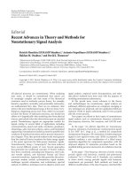
University of Michigan grad. student Ulrich Raschke verifies the proper alignment of ultrasonic sensors. All
three robots in this picture use 15 -angular spacing between the sensors. Many researchers agree that 15
o o
spacing assures complete coverage of the area around the robot.
References
Subject Index
Author Index
REFERENCES
1. Abidi, M. and Chandra, T., 1990, “Pose Estimation for Camera Calibration and Landmark
Tracking.” Proceedings of IEEE International Conference on Robotics and Automation,
Cincinnati, OH, May 13-18, pp. 420-426.
2. Abidi, M. and Gonzalez, R., Editors, 1992, Data Fusion in Robotics and Machine Intelligence.
Academic Press Inc., San Diego, CA.Acuna, M.H. and Pellerin, C.J., 1969, “A Miniature Two-
Axis Fluxgate Magnetometer.” IEEE Transactions on Geoscience Electronics, Vol. GE-7, pp
252-260.
3. Adams, M.D., 1992, “Optical Range Data Analysis for Stable Target Pursuit in Mobile Robotics.”
Ph.D. Thesis, Robotics Research Group, University of Oxford, U.K.
4. Adams, M. et al., 1994, “Control and Localisation of a Post Distributing Mobile Robot.” 1994
International Conference on Intelligent Robots and Systems (IROS '94), Munich, Germany, Sept.
12-16, pp. 150-156.
5. Adams, M., 1995, “A 3-D Imaging Scanner for Mobile Robot Navigation.” Personal
Communication. Contact: Dr. Martin Adams, Institute of Robotics, Leonhardstrasse 27, ETH
Centre, CH-8092, Switzerland. Ph.: +41-1-632-2539. E-mail:
6. Adams, M.D. and Probert, P.J., 1995, “The Interpretation of Phase and Intensity Data from
A.M.C.W. Light Detection Sensors for Reliable Ranging.” Accepted for publication in the IEEE
International Journal of Robotics Research, April.
7. Adrian, P., 1991, “Technical Advances in Fiber-Optic Sensors: Theory and Applications.”
Sensors, Sept.pp. 23-45.
8. Agent, A., 1991, “The Advantages of Absolute Encoders for Motion Control.” Sensors, April,
pp. 19-24.
9. Allen, D., Bennett, S.M., Brunner, J., and Dyott, R.B., 1994, “A Low Cost Fiber-optic Gyro for
Land Navigation.” Presented at the SPIE Annual Meeting, San Diego, CA, July.
10. Arkin, R.C., 1989, “Motor-Schema-Based Mobile Robot Navigation.” International Journal
of Robotics Research, Vol. 8., No. 4, Aug., pp. 92-112.
11. Aronowitz, F., 1971, “The Ring Laser Gyro,” Laser Applications, Vol. 1, M. Ross, ed.,
Academic Press.
12. Arradondo-Perry, J., 1992, “GPS World Receiver Survey.” GPS World, January, pp. 46-58.
13. Atiya, S. and Hager, G., 1993, “Real-time Vision-based Robot Localization.” IEEE
Transactions on Robotics and Automation, Vol. 9, No. 6, pp. 785-800.
14. Aviles, W.A. et al., 1991, “Issues in Mobile Robotics: The Unmanned Ground Vehicle Program
Teleoperated Vehicle (TOV).” Proceedings of the SPIE - The International Society for Optical
Engineering, Vol: 1388 p. 587-97.
15. Avolio, G., 1993, “Principles of Rotary Optical Encoders.” Sensors, April, pp. 10-18.
References 237
16. Ayache N. and Faugeras, O.D., 1987, “Building a Consistent 3-D Representation of a Mobile
Robot Environment by Combining Multiple Stereo Views.” Proc. Internaltional Joint
Conference on Aritificial Intelligence, pp. 808-810.
17. Baines, N. et al., 1994, “Mobile Robot for Hazardous Environments.” Unpublished paper.
Atomic Energy of Canada, Ltd., Sheridan Research Park, 2251 Speakman Drive, Mississauga,
Ontario, L5K 1B2, Canada, 416-823-9040.
18. Baker, A., 1993, “Navigation System Delivers Precision Robot Control.” Design News, Dec.
20, p. 44.
19. Banzil, G., et. al., 1981, “A Navigation Subsystem Using Ultrasonic Sensors for the Mobile
Robot Hilare.” Proceedings of 1 Conference on Robot Vision and Sensory Control,
st
Stratford/Avon, U.K., April 13.
20. Barrett, C.R., Nix, W.D., and Tetelman, A.S., 1973, “The Principles of Engineering
Materials.” Prentice Hall, Englewood Cliffs, NJ.
21. Barshan, B. and Durrant-Whyte, H.F., 1993, “An Inertial Navigation System for a Mobile
Robot.” Proceedings of the 1993 IEEE/RSJ International Conference on Intelligent Robotics
and Systems, Yokohama, Japan, July 26-30, pp. 2243-2248.
22. Barshan, B. and Durrant-Whyte, H.F., 1994, “Orientation Estimate for Mobile Robots Using
Gyroscopic Information.” 1994 International Conference on Intelligent Robots and Systems
(IROS '94). Munich, Germany, Sept. 12-16, pp. 1867-1874.
23. Barshan, B. and Durrant-Whyte, H.F., 1995, “Inertial Navigation Systems Mobile Robots.”
IEEE Transactions on Robotics and Automation, Vol. 11, No. 3, June, pp. 328-342.
24. Bauer, R. and Rencken, W. D., 1995, "Sonar Feature Based Exploration." Proceedings of the
IEEE/RSJ/GI International Conference on Intelligent Robots and Systems (IROS'95),
Pittsburgh, Pennsylvania, August 5-9,, pp. 148-153.
25. Benayad-Cherif, F., Maddox, J., and Muller, L., 1992, “Mobile Robot Navigation Sensors.”
Proceedings of the 1992 SPIE Conference on Mobile Robots, Boston, MA, Nov. 18-20, pp.
378-387.
26. Bennett, S. and Emge, S.R., 1994, “Fiber-optic Rate Gyro for Land Navigation and Platform
Stabilization.” Presented at Sensors Expo '94, Cleveland, OH, Sept. 20.
27. Betke, M and Gurvits, L., 1994, “Mobile Robot Localization Using Landmarks.” 1994
International Conference on Intelligent Robots and Systems (IROS’94). Munich, Germany,
Sept. 12-16, pp.135-142.
28. Beyer, J., Jacobus, C., and Pont, F., 1987, “Autonomous Vehicle Guidance Using Laser Range
Imagery.” SPIE Vol. 852, Mobile Robots II, Cambridge, MA, Nov, pp. 34-43.
29. Biber, C., Ellin, S., and Shenk, E., 1987, “The Polaroid Ultrasonic Ranging System.” Audio
Engineering Society, 67 Convention, New York, NY, Oct Nov.
th
30. Binger, N. and Harris, S.J., 1987, “Applications of Laser Radar Technology.” Sensors, April,
pp. 42-44.
238 References
31. Boltinghouse, S., Burke, J., and Ho, D., 1990, “Implementation of a 3D Laser Imager Based
Robot Navigation System with Location Identification.” SPIE Vol. 1388, Mobile Robots V,
Boston, MA, Nov., pp. 14-29.
32. Boltinghouse, S. and Larsen, T., 1989, “Navigation of Mobile Robotic Systems Employing a
3D Laser Imaging Radar.” ANS Third Topical Meeting on Robotics and Remote Systems,
Section 2-5, Charleston, SC, March, pp. 1-7.
33. Bolz, R.E. and Tuve, G.L., Ed., 1979, CRC Handbook of Tables for Applied Engineering
Science, CRC Press, Boca Raton, FL.
34. Borenstein, J. and Koren, Y., 1985, “A Mobile Platform For Nursing Robots.” IEEE
Transactions on Industrial Electronics, Vol. 32, No. 2, pp. 158-165.
35. Borenstein, J. and Koren, Y., 1986, “Hierarchical Computer System for Autonomous Vehicle.”
Proceedings of the 8th Israeli Convention on CAD/CAM and Robotics, Tel-Aviv, Israel,
December 2-4.
36. Borenstein, J., 1987, “The Nursing Robot System.” Ph. D. Thesis, Technion, Haifa, Israel,
June, pp. 146-158.
37. Borenstein, J. and Koren, Y., 1987, “Motion Control Analysis of a Mobile Robot.”
Transactions of ASME, Journal of Dynamics, Measurement and Control, Vol. 109, No. 2, pp.
73-79.
38. Borenstein, J. and Koren, Y., 1990, “Real-Time Obstacle Avoidance for Fast Mobile Robots
in Cluttered Environments.” IEEE International Conference on Robotics and Automation,
Vol. CH2876-1, Cincinnati, OH, pp. 572-577, May.
39. Borenstein, J. and Koren, Y., 1991a, “The Vector Field Histogram Fast Obstacle-Avoidance
for Mobile Robots.” IEEE Journal of Robotics and Automation, Vol. 7, No. 3., June, pp.
278-288.
40. Borenstein, J, and Koren, Y., 1991, "Histogramic In-motion Mapping for Mobile Robot
Obstacle Avoidance." IEEE Journal of Robotics and Automation, Vol. 7, No. 4, 1991, pp.
535-539.
41. Borenstein, J., 1992, “Compliant-linkage Kinematic Design for Multi-degree-of-freedom
Mobile Robots .” Proceedings of the SPIE Symposium on Advances in Intelligent Systems,
Mobile Robots VII, Boston, MA, Nov. 15-20, pp. 344-351.
42. Borenstein, J., 1993, “Multi-layered Control of a Four-Degree-of-Freedom Mobile Robot With
Compliant Linkage.” Proceedings of the 1993 IEEE International Conference on Robotics and
Automation, Atlanta, GA, May 2-7, pp. 3.7-3.12.
43. Borenstein, J., 1994a, “The CLAPPER: A Dual-drive Mobile Robot with Internal Correction
of Dead-reckoning Errors.” Proceedings of IEEE International Conference on Robotics and
Automation, San Diego, CA, May 8-13, pp. 3085-3090.
44. Borenstein, J., 1994b, “Internal Correction of Dead-reckoning Errors With the Smart Encoder
Trailer.” 1994 International Conference on Intelligent Robots and Systems (IROS '94).
Munich, Germany, Sept. 12-16, pp. 127-134.
References 239
45. Borenstein, J., 1994c, “Four-Degree-of-Freedom Redundant Drive Vehicle With Compliant
Linkage.” Video Proceedings of the 1994 IEEE International Conference on Robotics and
Automation, San Diego, CA, May 8-13.
46. Borenstein, J. and Feng, L., 1994, “UMBmark — A Method for Measuring, Comparing, and
Correcting Dead-reckoning Errors in Mobile Robots.” Technical Report, The University of
Michigan UM-MEAM-94-22, Dec.
47. Borenstein, J., 1995a, “Control and Kinematic Design for Multi-degree-of-freedom Mobile
Robots With Compliant Linkage.” IEEE Transactions on Robotics and Automation, Vol. 11,
No. 1, Feb., pp. 21-35.
48. Borenstein, J., 1995b, "Internal Correction of Dead-reckoning Errors With the Compliant
Linkage Vehicle." Journal of Robotic Systems, Vol. 12, No. 4, April, pp. 257-273.
49. Borenstein, J. and Koren, Y., 1995, “Error Eliminating Rapid Ultrasonic Firing for Mobile
Robot Obstacle Avoidance.” IEEE Transactions on Robotics and Automation, Vol. 11, No.
1, Feb., pp 132-138.
50. Borenstein, J., Wehe, D., Feng, C., and Koren, Y., 1995, “Mobile Robot Navigation in Narrow
Aisles with Ultrasonic Sensors.” Presented at the ANS 6th Topical Meeting on Robotics and
Remote Systems, Monterey, CA, Feb. 5-10.
51. Borenstein, J. and Feng, L., 1995a, “Measurement and Correction of Systematic Odometry
Errors in Mobile Robots." Accepted for publication as a regular paper in the IEEE
Transactions on Robotics and Automation, Apr.
52. Borenstein, J. and Feng. L., 1995b, “Correction of Systematic Dead-reckoning Errors in
Mobile Robots.”Proceedings of the 1995 International Conference on Intelligent Robots and
Systems (IROS '95), Pittsburgh, PA, Aug. 5-9, pp. 569-574.
53. Borenstein, J. and Feng. L., 1995c, “UMBmark: A Benchmark Test for Measuring Dead-
reckoning Errors in Mobile Robots.” 1995 SPIE Conference on Mobile Robots, Philadelphia,
October 22-26.
54. Borenstein, J., 1995, Video, “The CLAPPER: A Dual-drive Mobile Robot With Internal
Correction of Dead-reckoning Errors.” Video Proceedings of the 1995 IEEE International
Conference on Robotics and Automation, Nagoya, Japan, May 21-27.
55. Borenstein J. and Feng, L., 1996, "Gyrodometry: A New Method for Combining Data from
Gyros and Odometry in Mobile Robots." Accepted for presentation at the 1996 IEEE
International Conference on Robotics and Automation, Minneapolis, Apr. 22-28, 1996.
56. Brooks, R., 1985, “Visual Map Making for a Mobile Robot.” Proceedings of IEEE
International Conference on Robotics and Automation, St. Louis, MO, March 25-28, pp. 824-
829.
57. Brown, R.G., Hwang, P.Y.C., 1992, Introduction to Random Signals and Applied Kalman
Filtering. 2nd ed., John Wiley and Sons, New York, NY.
58. Buchberger, M., Jörg, K., and Puttkamer, E., 1993, “Laserradar and Sonar Based World
Modeling and Motion Control for Fast Obstacle Avoidance of the Autonomous Mobile Robot
240 References
MOBOT-IV.” Proceedings of IEEE International Conference on Robotics and Automation,
Atlanta, GA, May 10-15, pp. 534-540.
59. Buholz, N. and Chodorow, M., 1967, “Acoustic Wave Amplitude Modulation of a Multimode
Ring Laser.” IEEE Journal of Quantum Electronics, Vol. QE-3, No. 11, Nov., pp. 454-459.
60. Bulkeley, D., 1993, “The Quest for Collision-Free Travel.” Design News, Oct. 4.
61. Burns, W.K., Chen, C.L., and Moeller, R.P., 1983, “Fiber-Optic Gyroscopes with Broad-Band
Sources.” IEEE Journal of Lightwave Technology, Vol. LT-1, p. 98.
62. Byrd, J.S. and DeVries, K.R., 1990, “A Six-Legged Telerobot for Nuclear Applications
Development, International Journal of Robotics Research, Vol. 9, April, pp. 43-52.
63. Byrne, R.H., 1993, “Global Positioning System Receiver Evaluation Results.” Sandia Report
SAND93-0827, Sandia National Laboratories, Albuquerque, NM, Sept.
64. Byrne, R.H., Klarer, P.R., and Pletta, J.B., 1992, “Techniques for Autonomous Navigation.”
Sandia Report SAND92-0457, Sandia National Laboratories, Albuquerque, NM, March.
65. Cao, Z., Roning, J., and Hall, E., 1986, “Omnidirectional Vision Navigation Integrating Beacon
Recognition with Positioning.” Proceedings of the 1986 SPIE Conference on Mobile Robots,
Cambridge, MA, Oct. 30-31, pp. 213-220.
66. Carter, E.F., Ed., 1966, Dictionary of Inventions and Discoveries, Crane, Russak, and Co.,
New York, NY.
67. Case, M., 1986, “Single Landmark Navigation by Mobile Robot.” Proceedings of the 1986
SPIE Conference on Mobile Robots, Cambridge, MA, Oct. 30-31, pp. 231-237.
68. Chao, S., Lim, W.L., and Hammond, J.A., 1984, “Lock-in Growth in a Ring Laser Gyro.”
Proceedings, Physics and Optical Ring Gyros Conference, SPIE Vol 487, Snowbird, UT,
January, pp. 50-57.
69. Chen, H.H., 1991, “Pose Estimation from Line-to-Plane Correspondences.” IEEE Transaction
on Pattern Analysis and Machine Intelligence, vol. 13, no. 6, pp. 530-541.
70. Chen, S. and Tsai, W., 1991, “Determination of Robot Locations by Common Object Shapes.”
IEEE Transactions on Robotics and Automation, Vol. 7, No. 1, pp. 149-156.
71. Chen, Y.D., Ni, J., and Wu, S.M., 1993, “Dynamic Calibration and Compensation of a 3D
Lasar Radar Scanning System.” IEEE International Conference on Robotics and Automation,
Atlanta, GA, Vol. 3, May, pp. 652-664.
72. Chenavier, F. and Crowley, J., 1992, “Position Estimation for a Mobile Robot Using Vision
and Odometry.” Proceedings of IEEE International Conference on Robotics and Automation,
Nice, France, May 12-14, pp. 2588-2593.
73. Chesnoy, J., 1989, “Picosecond Gyrolaser.” Optics Letters, Vol 14, No. 18, Sept., pp. 990-
992.
74. Chow, W.W., Gea-Banacloche, J., Pedrotti, L.M., Sanders, V.E., Schleich, W., and Scully,
M.O., 1985, “The Ring Laser Gyro.” Reviews of Modern Physics, Vol. 57, No. 1, January, pp.
61-104.