Machine Learning and Robot Perception - Bruno Apolloni et al (Eds) Part 4 potx
Bạn đang xem bản rút gọn của tài liệu. Xem và tải ngay bản đầy đủ của tài liệu tại đây (706.63 KB, 25 trang )
68
M. Yeasin and R. Sharma
2.4 Space-variant Vision Sensor
With the introduction of biological concepts, the space-variant vision architecture and issues related to this is gaining momentum, especially in the
field of robotic vision and image communication. In designing a visual
sensor for an autonomous robot or any other visual system in which the
constraints of performance, size, weight, data reduction and cost must be
jointly optimized, five main requirements are imposed: (1) a high resolution fovea for obtaining details in the region of interest, (2) a wide field of
view useful for many tasks, for example, interest point determination,
(3) fast response time5, (4) smooth variation of resolution across the visual
work space and finally, (5) the cost, size and performance6 of the sensor.
To develop a space-variant vision sensor, several attempts to combine
peripheral and foveal vision have already been made in the past decades.
For example, space-variant image sampling [55] and combination of wide
and tele cameras [56, 57], but such methods are not discussed in this chapter as they do not fit in to the context of our discussion. Studies reveal that
there are mainly two types of space-variant sensors available and the clarification of this issue will go a long way towards clarifying several basic issues. First, one could work in ‘cortical’ plane, which has fundamentally
different geometry than the ‘retina’, but in which the size of the pixels increases towards the periphery. Second, one in which the image geometry is
still Cartesian, but retains the same space-variance in the pixel structure.
Successful efforts in developing space-variant sensors are summarized in
subsequent subsections.
2.4.1 Specially Designed Lens
This approach combines a wide field of view and a high resolution fovea
by specially designed lens. The purely optical properties of this method
avoid most of the problems involved in space-varying sensor design and
implementation, e.g., co-axial parallelism, continuity, hardware redundancy and computational cost. The foveated wide-angle lenses to build
space-varying sensors reported in [29] follow the design principles proposed in [58], while improving visual acuity in the fovea, and providing a
5 Low space-complexity i.e. a small fast to process output image. The space complexity of a vision
system is a good measure of the computational complexity, since the number of pixel which must
be processed is the space-complexity. Thus, even though the space-complexity does not entirely determine the computational complexity (which depends on many factors and specification of the algorithm), it is believed that the computational complexity is likely to be proportional to spacecomplexity.
6 The sensor must preserve the translational and rotational invariance property.
2 Foveated Vision Sensor and Image Processing – A Review
69
constant, low image compression rate in the periphery which can be useful
for periphery-based motion detection. Drawbacks associated with this kind
of approach include low photo-sensitivity in the periphery and strong optical deformations in the images that can be challenging for object recognition algorithms. We describe an instance of a complete system in the next
subsection to introduce the reader to the related development.
It is important to note that getting an space-varying sensor itself does
not solve the problem, the very spirit it has been chosen. It is important to
place them strategically (like human visual system), i.e., we need proper
platform to make the information extraction process easier. One such architecture is ESCHeR, an acronym for Etl Stereo Compact Head for Robot vision, is a custom designed high performance binocular head [59]. Its
functionalities are very much inspired by the physiology of biological visual systems. In particular, it exhibits many characteristics similar to human
vision: Certainly, the most distinguishing and unique feature of ESCHeR
lies in its lenses. Although rarely found in robotic systems, foveal vision is
a common characteristic of higher vertebrates. It is an essential tool that
permits both a global awareness of the environment and a precise observation of fine details in the scene. In fact, it is also responsible to a great extent for the simplicity and robustness of the target tracking.
ESCHeR was one of the first binocular heads that combines high dynamic performance, in a very compact and light design, with foveal and
peripheral vision. The lenses provide the ability to globally observe the environment and precisely analyze details in the scene, while the mechanical
setup is capable of quickly redirecting the gaze and smoothly pursue moving targets.
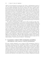
Fig. 2. 4: ESCHeR, a high performance binocular head. A Picture of ESCHeR
(left), the lens projection curve (middle), and an image of a face (right) taken with
its foveated wide-angle lenses (adopted from [60])
70
M. Yeasin and R. Sharma
2.4.2 Specially Designed Chips
This foveated sensor has been designed by several groups from the University of Genoa, Italy, University of Pennsylvania, USA, Scoula Superore
S Anna of Pisa, and has been fabricated by IMEC in Leuven, Belgium [61,
62, 63]. It features a unique concept in the VLSI implementation of a vision chip. The foveated chip, which uses a CCD process, mimics the
physically foveated retina of human. This approach in designing a foveated
sensor adopts a distribution of receptors of size gradually increasing from
the center to the periphery. The chip has a foveated rectangular region in
the middle with high resolution and a circular outer layer with decreasing
resolution. This mapping provides a scale and rotation invariant transformation. The chip has been fabricated using a triple-poly buried channel
CCD process provided by IMEC. The rectangular inner region has 102
photo-detectors. The prototype has the following structure: the pixels are
arranged on 30 concentric circles each with 64 photosensitive sites. The
pixel size increases from 30 micron × 30 micron to 412 micron × 412 micron from the innermost circle to the outermost circle. The total chip area
is 11 mm × 11 mm. The video acquisition rate is 50 frames per second.
The total amount of information stored is less than 2 Kbytes per frame.
Thus, the chip realizes a good trade-off between image resolution, amplitude of the visual field and size of the stored data. In references [61, 62,
63] other aspects of the design, such as read-out structures, clock generation, simple theories about the fovea, and hardware interface to the chip are
described.
The foveated CMOS chip designed by by the IMEC and IBIDEM consortium [Ferrari et al. 95b, Ferrari et al. 95a, Pardo 94], and dubbed
“FUGA”, is similar to the CCD fovea described in Section 2.11 [van der
Spiegel et al. 89]. The rectangularly spaced foveated region in the CCD
retina has been replaced by reconfiguring the spatial placement of the
photo-detectors. As a result of this redesign, the discontinuity between fovea and the peripheral region has been removed. In the CCD retina a blind
sliced region (for routing the clock and control signals) exists. In the
FUGA18 retina the need to this region has been removed by routing the
signals through radial channels.
A latest version of the sensor has been designed by the IMEC and
IBIDEM consortium using [64, 62] the CMOS technology, without compromising the main feature of the retina-like arrangement. In the CCD retina a blind sliced region (for routing the clock and control signals) exists
but in CMOS version this has been removed by routing the signals through
radial channels. Several versions of the FUGA chip with different sizes
have been designed and manufactured by IMEC. Most recent version of
2 Foveated Vision Sensor and Image Processing – A Review
71
this sensor 30, 000 pixels, a figure allowing a 3 to 4 times increase with respect to the old CMOS chip which has 8, 013 pixels. The color version of
the chip was obtained by micro-deposition of filters over the monochromatic layout. The pixel’s layout is the same as the IBIDEM retina and is
composed of 8, 013 pixels.
Wodnicki et. al. [65, 66] have also designed and fabricated a foveated
CMOS sensor. The fovea photo-detectors are uniformly spaced in a rectangle and the periphery photo-detectors are placed in a circular array. The
pixel pitch in the fovea is 9.6µm in a 1.2µm process. This degree of resolution requires substrate biasing connection to be located outside of the sensor matrix. Photo-detectors have been realized using circular parasitic well
diodes operating in integrating mode. Biasing is accomplished with a ring
of p4 diffusion encircling the sensor matrix. The area of the photo detector
in the circular outer region increases exponentially, resulting in the logpolar mapping. The chip has been fabricated in a 1.2µm CMOS process. It
has 16 circular layers in the periphery. The chip size is 4.8 mm × 4.8 mm.
2.4.3 Emulated Chips
Apart from the above, few other emulated sensor implementation has
been reported in the literature. For example, the AD2101 and TI320C40
are DSP’s used in cortex I and cortex II [67], respectively, with conventional CCD (e.g., Texas-Instruments TC211 CCD used in Cortex-I) to
emulate log-map sensor. The log(z + a) mapping model has been used instead of mapping the foveal part with polar mapping and periphery with
logarithmic mapping. This ensures the conformality of the mapping at the
cost of managing a discontinuity along the vertical-midline. In a similar
manner, another log-map sensor using an overlapping data reduction
model has been reported in [41]. Next section focuses on image understanding tools to analyze space-variant images; in particular, the logmapped images.
2.5 Space-variant Image Processing
This chapter discusses the space-variant image processing in a deterministic framework. Humans are accustomed in thinking of an image as a rectangular grid of rectangular pixel where the connectivity and adjacency are
well defined. The scenario is completely different for a space-variant image representation. Consequently, image processing and pattern recognition algorithms become much more complex in space-variant systems than
72
M. Yeasin and R. Sharma
in standard imaging systems. There are several reasons for this, namely,
the complex neighborhood connectivity and the lack of shift invariant
processing. It is important to keep in mind that there are two types of space
variance and the clarification of this issue will go a long way towards clarifying several basic issues. First, one could work in a ‘retinal plane’ in
which the image geometry is still Cartesian, but the size of the pixels increases towards the periphery. Second, one could work in a ‘cortical’
plane, which has a fundamentally different geometry than the ‘retina’, but
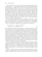
retains the same space-variance in the pixel structure. Fig. 2.5 shows an
example of a log-polar mapped image. From Fig. 2.5 it is readily seen that
image feature changes size and shape as it shifts across the field of a spacevariant sensor. The frequency-domain and the spatial domain image processing techniques to process such a complicated image are reviewed in
subsequent subsections.
2.5.1 Space-variant Fourier Analysis
As mentioned earlier, the shift-invariant property of the Fourier transform
does not hold since translation symmetry in the spatial domain is broken
by the space-variant properties of the map. It has been shown in [68, 69]
that it is indeed possible to solve the seemingly paradoxical problem of
shift invariance on a strongly space variant architecture. The following
subsections will systematically discuss the related developments.
Fig. 2.5: Illustration of complex neighborhood: (a) standard camera image, (b)
retinal plane representation of log-mapped image, (c) cortical plane representation
of the log-mapped image. The white line shows how the oval shape maps in logmapped plane
2 Foveated Vision Sensor and Image Processing – A Review
73
2.5.1.1 The Generalized Chirp Transform
Given a one dimensional signal f(x) and an invertible mapping or transformation : x
,
C 1 , the Fourier transform of f(x)
F( f )
f ( x)e
j 2 fx
By using the Jacobian in the
obtain,
(f)
f ( x( ))
x( )
(f, )
Defining a kernel as
dx .
(9)
space and by changing the notation one can
e
j 2 fx ( )
d .
x( )
e
(10)
j 2 fx ( )
, and rewriting equation
(10) one can get,
(f)
f ( x( )) ( f , )d .
(11)
The integral equation (11) is called the exponential chirp transform. A
close look at this equation reveals that the transform is invariant up to a
phase under translation in the x domain. This follows from the Fourier
shift theory which is simply transformed through the map function.
2.5.1.2 1-D Continuous Exponential Chirp Transform (ECT)
Let us consider the 1-D transformation7 7of the following form:
log( x a)
x 0,
2 log(a) log( x a ), x 0.
( x)
For which the kernel as in equation (11) is
j 2 f (e
e
2
a e
a)
j 2 f ( a a 2e
log(a )
)
log(a )
.
(12)
7 This represents a logarithmic mapping in which the singularity at the origin is removed by defining
two separate branches, using some finite positive ‘a’ to provide a linear map for ||x|| >> a.
74
M. Yeasin and R. Sharma
This kernel is reminiscent of a chirp with the exponentially growing frequency and magnitude. Hence, aliasing must be carefully handled, due to
the rapidly growing frequency of the kernel.
2.5.1.3 2-D Exponential Chirp Transform
Given a 2-D function f(x, y) and an invertible and differentiable transform : ( x, y )
( , ) , the 2-D ECT is defined by the following integral
transform:
( k , h)
( x( , ), y ( , )) ( , , k , h)d d ,
(13)
where k and h are the respective Fourier variables. The ECT in equation
(13) can be written as
f ( , )e 2 e
( k , h)
2 j ( k ( e cos( ) a ) he sin( ))
d d ,
(14)
D
where D is over the range
and
3
2
2
. From equation
(14) it is readily seen that the integral transform can be evaluated directly
with a complexity of O(M2N2), where M and N are the dimension of the
log-mapped image.
2.5.1.4 Fast Exponential Chirp Transform
The ECT in equation (14) can be written as
( k , h) e j 2
ak
f ( , )e 2 e
j 2 ( k ( e cos( ))) ( he sin( ))
d d .
(15)
D
By introducing the log-mapping in frequency, centered on the frequency
origin, it has been shown in [68] that the above equation can be written as
(r , ) e j 2
ak ( r , )
( f * ( , )e 2
j 2 be cos
)*e
j2
e( r
)
cos(
)
d d , (16)
D
where b is a real number and the superscript * stands for a complex conjugate of the function. From equation (16) it is simple to see that the ECT
can be computed as a complex correlation. The numerical implementation
2 Foveated Vision Sensor and Image Processing – A Review
75
of equation (16) is referred as the FECT88. The inverse FECT (IFECT), 2D
discrete ECT and their implementation details can be found in [68].
2.5.1.5 Antialiasing Filtering
When a signal is not sampled at a sufficiently high rate, aliasing error occurs in the reconstructed signal. In order to anti-alias, one must filter out
the set of samples from the exponential chirp kernel that do not satisfy the
following inequality:
log( R 1)
N v
N
.
log(2 )
N v
M
Where v , v
are the 2-D instantaneous frequencies of the complex ker-
nel, N and N are the Nyquist factors, and N and M are the length of the
vectors n and m, respectively. Antialiasing filtering can be achieved by
multiplying the kernel by the 2-D Fermi function
log( R 1)
N
N v ,
2
M
N v .
This function can be incorporated in the chirp transform and in equation
(16), giving the following cross-correlation (b = 0):
e j2
ah ( , )
( f ( , )e 2 )e j 2
D
e(
) cos(
)
.
log( R 1)
N
N v ,
2
M
N v d d . (17)
The ECT described in this section has been used in [68] for image filtering, cross-correlation. It is simple to see that the ECT discussed in this section can used for the frequency domain analysis of space-variant images.
As the ECT guarantees the shift invariance hence it is straightforward to
adopt the ECT for phase-based vision algorithms (for example, phasebased disparity and phase-based optical flow and etc.).
8 This is a slightly different usage than, for example, the FFT where the fast version of the DFT produces result identical to the DFT. The FECT produces results which are re-sampled versions of the
DECT due to the log-map sampling in the frequency. Although the FECT is a homeomorphism of the
log-mapped image (i.e. invertible and one to one), the DECT and FECT are not numerically identical.
76
M. Yeasin and R. Sharma
2.5.2 Space-variant Metric Tensor and Differential Operators
This section discusses the space-variant form of the
operator, which
yields the space-variant form of the gradient, divergence, curl and Laplacian operator.
2.5.2.1 Metric Tensor of the Log-mapping
The metric tensor is a multi-linear map which describes what happens to
an infinitesimal length element under the transformation. A useful way to
understand the effects of the log-mapping on the standard Cartesian operators is in terms of the metric tensor of the complex log domain. As the coordinate transform is space-variant, so does the metric tensor as a function
of the log coordinate. Formally, the metric tensor T of a transformation z
from a coordinate system ( , ) in to another coordinate system (x, y) is
given by
T
z ,z
z ,z
z ,z
x x
y y
x x
y y
z ,z
x x
y y
x x
y y
e2
0
0
,
e2
(18)
z i , z j stands for the inner product of the vectors. The diagonal
where
form of T is a direct consequence of conformal mapping. That is, the metric tensor of any conformal mapping has the form T = A ij (with equal
elements on the diagonal). From equation (18) it is apparent that as distance from the fovea increases, the Cartesian length of the log-domain vector is scaled by e . Conversely, the length of a Cartesian vector mapped
into the log-plane is shrinked by a factor of e- due to the compressive
logarithmic non-linearity.
2.5.2.2 Space-variant form of
Operator
A conformal mapping insures that the basis vector which are orthogonal in
the ( , ) space remains orthogonal when projected back to the Cartesian
space. Since the gradient is the combination of directional derivatives, one
is assured that the gradient in the log-space is of the form
f
A( , )
f
e
f
e
,
(19)
where e and e define the orthonormal basis, and A ( , ) is the term
that accounts for the length scaling of a vector under the log mapping. It
2 Foveated Vision Sensor and Image Processing – A Review
77
may be noted that equation (20) holds for any conformal mapping with the
specifics of the transformation expressed in the co-efficient function A. By
using the invariance of the magnitude of the gradient under a change of
coordinates it has been shown that the the space-variant form of
is
given by [47]:
e
e
e
,
(20)
which allows the direct computation of quantities such as derivative, divergence, curl and Laplacian operator in a log-mapped plane. It may be
noted here that this derivation does not account for the varying support of
each log-pixel. As one moves towards the periphery of the log-mapped
plane, each log-pixel is typically generated by averaging a larger region of
the Cartesian space, both in the mammalian retina and in machine vision
systems. The averaging is done to avoid aliasing in the periphery, and to
attenuate high frequency information, partially offsetting the need for a
negative exponential weighting to account for varying pixel separation. It
is simple to see that the space-variant gradient operator defined in this section will prove useful for performing low level spatial domain vision operations. Next section presents classic vision algorithms (space-variant optical flow, stereo disparity, anisotropic diffusion, corner detection and etc.)
on space-variant images.
2.6 Space-variant Vision Algorithms
As discussed in the previous sections, the elegant mathematical properties
and the synergistic benefits of the mapping allows us to perform many visual tasks with ease. While the implementation of vision algorithms on
space-variant images remains a challenging issue due to complex
neighborhood connectivity and also the lack of shape invariance under
translation. Given the lack of general image understanding tools, this section will discuss the computational issues of representative vision algorithms (stereo-disparity and optical flow), specifically designed for spacevariant vision system. In principle, one can use the spatial and the frequency domain operators discussed in previous sections to account for the
adjustment one needs to make to process space-variant images.
78
M. Yeasin and R. Sharma
2.6.1 Space-variant Optical Flow
From a biologist’s point of view, optical flow refers to the perceived motion of the visual field results from an individual’s own movement through
the environment. With optical flow the entire visual field moves, in contrast to the local motion of the objects. Optical flow provides two types of
cues: information about the organization of the environment and information about the control of the posture. In computer vision, optical flow has
commonly been defined as the apparent motion of image brightness patterns in an image sequence. But the common definition of optical flow as
an image displacement field does not provide a correct interpretation9 9
when dealing with light source motion or generally dominant shading effects. In a most recent effort to avoid this problem a revised definition of
optical flow has been given in [70]. It is argued that the new representation, describing both the radiometric and the geometric variations in an image sequence, is more consistent with the common interpretation of optical
flow. The optical flow has been defined as a three-dimensional transformation field, v [ x, y, I ]T , where [ x, y ] are the geometric component
and I is the radiometric component of the flow field. In this representation, optical flow describes the perceived transformation, instead of perceived motion, of brightness patterns in an image sequence.
The revised definition of optical flow permits the relaxation of the
brightness constancy model (BCM) where the radiometric component I
is explicitly used to be zero. To compute the optical flow, the so-called
generalized dynamic image model (GDIM) has been proposed; which allows the intensity to vary in the successive frames. In [70] the GDIM was
defined as follows:
I2 (x
x)
M ( x) I1 ( x) C ( x).
(21)
The radiometric transformation from I1 ( x) to I 2 ( x x) is explicitly defined in terms of the multiplier and the offset fields M(x) and C(x), respectively. The geometric transformation is implicit in terms of the correspondence between points x and x+ x. If one writes M and C in terms of
variations from one and zero, respectively, M ( x) 1 m( x) and
C ( x) 0 c( x) one can express GDIM explicitly in terms of the scene
brightness variation field
9
For example, a stationary viewer perceives an optical flow when observing a stationary scene that is
illuminated by a moving light source. Though there is no relative motion between the camera and
the scene, there is a nonzero optical flow because of the apparent motion of the image pattern
2 Foveated Vision Sensor and Image Processing – A Review
I2 (x
x) I1 ( x)
I1 ( x)
m( x ) I 1 ( x )
c( x) .
79
(22)
c 0 , the above model simplifies to the BCM. Despite a
Where m
wide variety of approaches to compute optical flow, the algorithms can be
classified into three main categories: gradient-based methods [71], matching techniques [72], and frequency-based approaches [73]. But a recent review [74] on the performance analysis of different kinds of algorithm suggests that the overall performances of the gradient-based techniques are
superior. Hence, in this chapter will discuss the gradient-based method to
compute the optical flow.
Though there are several implementations to compute the optical flow in
the log-polar images (i.e., [14, 7]), but most of the algorithm fails to take
into account some very crucial issues related log-polar mapping. Traditionally, the optical flow on space-variant images has been computed
based on the BCM using the Cartesian domain gradient operator. On the
contrary, the use of GDIM and employ the space-variant form of gradient
operator (see the previous section) to compute optical flow on log-mapped
image plane [75].
Using the revised definition of the optical flow and by requiring the
flow field to be constant within a small region around each point, in [76,
77], it was shown that the optical flow on a log-mapped image plane can
be computed by solving system of equations
I
2
I I
I I
I
2
I I
I
v
I It
I I
I
v
I It
2
I
m
I
c
I I
II
I
I
W
I
I
II t
It
,
(23)
where W is a neighborhood region. Please note that in a log-mapped image
this neighborhood region is complicated and variable due to the nonlinear
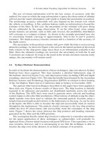
properties of the logarithmic mapping. A notion called a variable window
(see Fig. 2.6) i.e., a log-mapped version of the standard Cartesian window,
to preserve the local neighborhood on a log-mapped image is used to address the above problem. From Fig. 2.6(c) it is very easy to see that the
size and shape of the window varies across the image plane according to
the logarithmic mapping. Also the use of space-variant derivative operator
was used to compute the derivative on log-mapped plane. The use of space
variant form of the derivative operator is important for a better numerical
accuracy as the mapping preserves the angles between the vectors, but not
the magnitude.
80
M. Yeasin and R. Sharma
By solving equations (23) one can compute the optical flow directly on
log-mapped images. The GDIM-based model permits us to relax the
brightness constancy model (BCM) by allowing the intensity to vary in the
successive frames. If one explicitly set the radiometric component I to
zero the GDIM models boils down to the BCM. In other words, the BCM
assumption holds where the multiplier field m = 0 and the offset field c =
0. The multiplier and the offset field can become discontinuous at iso lated
boundaries, just as image motion is discontinuous at occluding or motion
boundaries. As a result, the estimated radiometric and geometric components of optical flow may be inaccurate in these regions. Erroneous
Fig. 2.6: An illustration of variable window: (a) A Cartesian window, (b) logmapped window and (c) computed shape of windows across the image plane result
may be detected by evaluating the residual squared-error. It has been shown that
the inclusion of the above features significantly enhances the accuracy of optical
flow computation directly for the log-mapped image plane (please see [75, 77])
2.6.2 Results of Optical Flow on Log-mapped Images
As mentioned earlier, the log-mapping is conformal, i.e., it preserves local
angles. Empirical study were conducted with both the synthetic and the
real image sequences. For real image sequences, indoor laboratory, an outdoor and an underwater scene were considered to show the utility of the
proposed algorithm. Synthetically generated examples include the computed image motion using both the BCM and GDIM-based method to
demonstrate the effect of neglecting the radiometric variations in an image
sequence. In order to retain this property after discretization, it is wise to
keep identical discretization steps in radial and angular directions.
2 Foveated Vision Sensor and Image Processing – A Review
81
2.6.2.1 Synthetic Image Sequences
The first image is that of a textured 256 × 256 face image (see Fig. 2.7(a)).
Using a known motion (0.4 pixel horizontal motion in the Cartesian space
which corresponds to 0 30 pixel image motion in the log-mapped image)
and a radiometric transformation field (a Gaussian distribution of radiometric transformation field ( m) in the range between 0.8 1.0 and c =
0), were used to compute the second image. The third image was derived
from the first image using the above radiometric transformation only. Two
sequences using frame 1 2 and 1 3 are considered. Fig. 2.7(b) shows a
sample transformed log-mapped image of (derived from Fig. 2.7(a)).
Fig. 2.7: Simulated optical flow: (a) a traditional uniformly sampled image, (b)
log-map representation of the uniformly sampled image, and (c) true image motion used to generate synthetic image sequences
The peripheral part of the image i.e., the portion of the log-mapped image right to the white vertical line for the computation of optical flow (see
Fig. 2.7(b)). The idea of using the periphery stems from biological motivation and also to increase the computational efficiency. It may be noted that
the same algorithm will hold incase of computation of the optical flow for
the full frame. It is also important to recognize that the computation of optical flow on the peripheral part is hard as the resolution decreases towards
the periphery.
To analyze the quantitative performance the error statistics for both the
BCM and GDIM methods are compared. The error measurements used
here are the root mean square (RMS) error, the average relative error
(given in percentage), and the angular error (given in degrees). The average relative error in some sense gives the accuracy of the magnitude part
while the angular error provides information related to phase of the flow
field. Compared are, at a time, the two vectors (u, v, 1) and (ˆu, ˆv, 1),
where (u, v) and (ˆu, ˆv) are the ground truth and estimated image motions,
respectively. The length of a flow vector is computed using the Euclidean
82
M. Yeasin and R. Sharma
norm. The relative error between two vectors is defined as the difference
of length in percentage between a flow vector in the estimated flow field
and the corresponding reference flow field:
|| (u u , v v) ||2
|| (u , v) ||2
.100 .
(24)
The angular error between two vectors is defined as the difference in
degrees between the direction of the estimated flow vector and the direction of the corresponding reference flow vector.
Fig. 2.8: Computed optical flow in case of both geometric and radiometric transformations. Figures 2.8(a) and 2.8(b) represents the computed flow field using
BCM and GDIM methods, respectively.
Synthetically generated images with ground truth were used to show
both the qualitative and the quantitative performance of the proposed algorithm. Figure 2.7(c) shows the true log-mapped image motion field which
has been used to transform the image sequence 1 2. Figures 2.8(a) and
2.8(b) show the computed image motion as Quiver diagram for the sequence 1 2 using the BCM and GDIM, respectively. The space-variant
form of gra-dient operator and variable window were used to compute the
optical flow for both the GDIM-based and BCM-based method. A visual
comparison of the Fig. 2.6(c) with Figs. 2.8(a) and 2.8(b) reveals that the
image motion field estimated using GDIM method is similar to that of the
true image motion field, unlike the BCM method. This result is not surprising as the BCM method ignores the radiometric transformation. To provide
a quantitative error measure and to compare the performance of the proposed algorithm with the traditional method; the average relative error,
2 Foveated Vision Sensor and Image Processing – A Review
83
which in some sense reflects the error in estimating the magnitude of the
flow field were used. It was found that the average relative error 7.68 and
6.12 percent for the BCM and GDIM, respectively.
Fig. 2.9: Computed optical flow in case of radiometric transformation. Figures
2.9(a) and 2.9(b) represents the computed flow using BCM and GDIM, respectively
To provide more meaningful information about the error statistics the
average angular error which in some sense reflects the error in estimating
the phase of the flow field were also computed. The average angular error
was found to be 25.23 and 5.02 degree for the BCM and GDIM, respectively. The RMS error was found to be 0.5346 and 0.1732 for the BCM
and the GDIM method, respectively. The above error statistics clearly indicates that the performance of the proposed GDIM-based method is superior to the BCM method. Figs. 9(a) and 9(b) displays the computed optical
flow using sequence 1 3, where there is no motion (only the radiometric
transformation has been considered to transform the image). It is clear
from the Fig. 2.9(a), when employing BCM; one obtains the erroneous interpretation of geometric transformation due to the presence of radiometric
variation. On the contrary, the proposed GDIM-based method shows no
image motion (see Fig. 2.9(b)), which is consistent with ground truth. Figs.
10(a)- 10(d) shows the mesh plot of the true and computed and
components of the image motion, respectively. From Figs. 10(a)-10(d) it is
evident that the proposed method estimated the spatial distribution of the
image motion quite accurately.
2.6.2.2 Real Image Sequences
To further exemplify the robustness and accuracy of the proposed method,
empirical studies were conducted using real sequence of images captured
84
M. Yeasin and R. Sharma
under both the indoor and the outdoor a well as using under water camera
by fixing the camera parameters. The motion for the under water and the
outdoor sequence of images were dominantly horizontal motion, while the
motion for the indoor laboratory was chosen to be the combination of rotation and horizontal translational motion. In all experiments the peripheral
portion of images i.e., right side to the white vertical line (see Figs.
2.11(b), 2.12(b) and 2.13(b)) were used for the computation of optical
flow. Figures 2.11(a)–(c), 2.12(a)–(c) and 2.13(a)–(c) shows a sample
frame, log-polar transformed image and the computed image motion for
under water, outdoor and indoor scenery images, respectively.
Fig. 2.10: Quantitative comparison of true flow and computed flow using GDIM
method. (a) and (b) shows the true flow and (c) and (d) shows the computed flow
in the radial and angular directions, respectively
2 Foveated Vision Sensor and Image Processing – A Review
85
Fig. 2.11: Optical flow computation using an under water scene. (a) sample image
from the under water scene; (b) the log-mapped transformed image and, (c) the
computed image motion using GDIM-based method
Fig. 2.12: Similar results as shown in Fig. 2.11 using an outdoor scene
From Figs. 2.11(c) and 2.12(c) it is clear that the flow distributions for
the underwater and outdoor scenery images are similar to that of the Fig.
2.7(c), as expected. But, the flow distribution of the indoor laboratory sequence (see Fig. 2.13(c)) is different from that of the Fig. 2.7(c), due to the
different motion profile. As mentioned earlier, the rotation in the image
plane produces a constant flow along the radial direction. Hence, the flow
distribution of Fig. 2.13(c) can be seen as the superposition of the flow distribution of the translational flow and that of the constant angular flow.
These results show the importance of taking into account the radiometric
variation as well as the space-variant form of the derivative operator for
log-mapped images by providing a accurate image motion estimation and
unambiguous interpretation of image motion. It is clear from the results
that the proposed method is numerically accurate, robust and provides consistent interpretation. It is important to note that the proposed method has
error in computing optical flow. The main source of error is due to the
non-uniform sampling.
86
M. Yeasin and R. Sharma
Fig. 2.13: Similar results shown in Fig. 2.11 using an indoor laboratory scene
2.6.2.3 Aperture Problem
P. Stumpf is credited (as translated in [78]) with first describing the aperture problem in motion analysis. The aperture problem arises as a consequence of the ambiguity of one-dimensional motion of a simple striped
pattern viewed through an aperture. The failure to detect the true direction
of motion is called the aperture problem. In other words, the motion of a
homogeneous contour is locally ambiguous [79-81], i.e., within the aperture, different physical motions are indistinguishable.
In the context of primate vision, a two-stage solution to the aperture
problem was presented in [82]. In machine vision literature, application of
some form of smoothness constraint has been employed to overcome the
aperture problem in devising techniques for computing the optical flow
(for example, [83-84]). The aperture problem is critical in case of log-polar
mapped images. As shown in section 3 straight lines are mapped into
curves. Since the aperture problem appears only in the case of straight
lines for the Cartesian images, the log-polar mapping seems to eliminate
the problem. This of course is not true. It may be noted that a circle in the
Cartesian image mapped on to a straight line in log-polar mapped image.
This means that the aperture problem appears at points in the log-polar
plane where the aperture problem does not occur in the corresponding
points in the Cartesian image. Alternatively, it is possible to compute optical flow at points in the log-polar plane where the corresponding Cartesian
point does not show curvature. Of course, the superficial elimination of the
aperture problem produces optical flow values that show large error regarding the expected motion field. The problem is much more complex
with GDIM model. If one assume, m = c = 0, the above model simplifies to the BCM. Mathematically, one of the two fields, say M is sufficient
to describe the radiometric transformation in an image sequence if this is
2 Foveated Vision Sensor and Image Processing – A Review
87
allowed to vary arbitrarily from point to point and one time instant to the
next. In this case the multiplier field is typically a complicated function of
several scene events that contribute to the radiometric transformation, each
of which may vary sharply in different isolated regions [70]. This is not
desirable since it then becomes very difficult to compute optical flow due
to the generalized aperture problem (please see [70] for details regarding
the generalized aperture problem).
2.6.3 Stereo Disparity
When a moving observer looks in the direction of heading, radial optical
flow is only one of several cues which indicate the direction of speed of
heading. Another cue, which is very significant at generating vergence at
ultra short latencies is binocular disparity [54]. The pattern of retinal binocular disparities acquired by a fixating visual system depends on both the
depth structure of the scene and the viewing geometry. In some binocular
machine vision systems, the viewing geometry is fixed (e.g., with approximately parallel cameras) and can be determined once and for all by a
calibration procedure. However, in human vision or any fixating vision
system, the viewing geometry changes continually as the gaze is shifted
from point to point in the visual field. In principle, this situation can be approached in two different ways: either a mechanism must be provided
which continuously makes the state of the viewing geometry available to
the binocular system, or invariant representations that fully or partially
side-step the need for calibration of the viewing geometry must be found.
For each approach a number of different techniques are possible, and any
combination of these may be used as they are not mutually exclusive.
The viewing geometry could in principle be recovered from extra-retinal
sources, using either in-flow or out-flow signals from the occulomotor
and/or accommodation systems. The viability of this approach has been
questioned on the ground that judgments of depth from occulomotor/accommodation information alone are poor [85, 86, 87, 40]. Alternatively, viewing geometry can be recovered from purely visual information,
using the mutual image positions of a number of matched image features
to solve for the rotation and translation of one eye relative to the other.
This is often referred to as the “relative orientation” [88]. For normal binocular vision the relative orientation problem need not be solved in its full
generality since the kinematics of fixating eye movements is quite constrained. These constraints lead to a natural decomposition of the disparity
field into a horizontal and vertical component, which carries most of the
depth information, and a vertical component, which mainly reflect the
viewing geometry.
88
M. Yeasin and R. Sharma
Apart from few exceptions [3, 89], most active vision researchers use
Cartesian image representations. For tracking, the main advantage of the
log-polar sensor is that objects occupying the central high resolution part
of the visual field become dominant over the coarsely sampled background
elements in the periphery. This embeds an implicit focus of attention in the
center of the visual field where the target is expected to be most of the
time. Furthermore, with Cartesian images, if the object of interest is small,
the disparity of the background can lead to erroneous estimate. In [54], it
has been argued that a biologically inspired index of fusion provides a
measure of disparity.
Disparity estimation on space-variant image representation has not been
fully explored. A cepstral filtering method is introduced in [90] to calculate
stereo disparity on columnar image architecture architecture for cortical
image representation [91]). In [92], it has been shown that the performance
of cepstral filtering is superior then phase-based method [93]. In [5] correlation of log-polar images has been used to compute the stereo disparity. It
has been argued that correlation based method works much better in logpolar images than for Cartesian images. It has been shown that correlation
between log-polar images corresponds to the correlation in Cartesian images weighted by the inverse distance to the image center. To account for
the translation in Cartesian domain (in the log-polar domain the translation
is very complicated) a global search for the horizontal disparity has been
proposed which minimizes the SSD.
It is believed that stereo disparity on a space-variant architecture can be
conveniently estimated using phase-based technique by computing the local phase difference of the signals using the ECT. As mentioned earlier,
ECT preserves the shift invariant property hence standard phase-disparity
relation holds. To cope with the local characteristics of disparity in stereo
images, it is standard practice to compute local phase using a complex
band-pass filters (for example, [94, 95]). It is important to note that one
needs to take a proper account of the aliasing and quantization issues to
compute the phase of the signals using the ECT discussed in the previous
section. A possible computational approach could be,
Step 1: Obtain the phase of left and right camera images using the ECTbased method.
Step 2: Calculate the stereo disparity using the standard phase-disparity
relationship.
For most natural head motions the eyes (cameras) are not held on precisely the same lines of sight, but it is still true that the angular component
of disparity is approximately independent of gaze. Weinshall [96] treated
2 Foveated Vision Sensor and Image Processing – A Review
89
the problem of computing a qualitative depth map from the disparity field
in the absence of camera calibration. Rather than decomposing disparity
vectors into horizontal and vertical components, Wienshall used a polar
decomposition and showed that two different measures derived from the
angular component alone contains enough information to compute an approximate depth ordering. It has also been established that a numerical
simulations showing that the pattern of polar angle disparities can be used
to estimate the slope of a planar surface up to scaling by fixation distance,
and that this pattern is affected by unilateral vertical magnification. In
summary, eccentricity- scaled log-polar disparity, which can be computed
from a single pair of corresponding points without any knowledge of the
viewing geometry, directly indicates relative proximity.
2.7 Discussions
Biological and artificial systems that share the same environment may
adopt similar solution to cope with similar problems. Neurobiologists are
interested in finding the solutions adopted by the biological vision systems
and machine vision scientists are interested in which of technologically
feasible solutions that are optimal or suited of building autonomous vision
based systems. Hence, a meaningful dialogue and reciprocal interaction
between biologists and engineers with a common ground may bring fruitful results. One good example could be finding a better retino-cortical
mapping model for sensor fabrication. It is believed that research in this
front will help in designing a much more sophisticated sensor which preserves complete scale and rotation invariance at the same time maintains
the conformal mapping. Another fundamental problem with space-variant
sensor arises from their varying connectivity across the sensor plane. Pixels that are neighbors in the sensor are not necessarily neighbors ones
computer reads data into array, making it difficult or impossible to perform
image array operations. A novel sensor architecture using a ‘connectivity
graph’ [97] or data abstraction technique may be another avenue which potentially can solve this problem.
Sensor-motor integration, in one form commonly known as eye-hand
coordination, is a process that permits the system to make and test hypotheses about objects in the environment. In a sense, nature invented the
scientific method for the nervous system to use as a means to predict and
prepare for significant events. The motor component of perception compensates for an uncooperative environment. Not only does the use of effectors provide mobility, but it alters the information available, uncovering
90
M. Yeasin and R. Sharma
new opportunities to exploit. The development of purposive movement allows the host to judiciously act in the environment and sample the results.
Prediction forms the basis of the judgment to act, and the results are used
to formulate new predictions. Hence an action-sensation-prediction-action
chain is established through experience and conditioned learning.
One behavioral piece of evidence for the action-sensation-prediction sequence is the scan path. The scan path is a sequence of eye (or camera)
saccades that sample a target in a regular way to collect information. The
scan path after learning became more regular and the inter-saccade interval
get reduced compared to the naive state. It is believed that an invariant
recognition can be achieved by transforming an appropriate behavior. For
example, a scan path behavior to an image at different sizes, the saccade
amplitudes must be modulated. This could be accomplished by the use of
the topographical mapping that permits a natural rescaling of saccade amplitude based upon the locus of activity on the output map. To change the
locus of activity, it is only necessary to match the expectation from the associative map with the available sensor information.
2.8 Conclusions
Anthropomorphic visual sensor and the implication of logarithmic mapping offer the possibility of superior vision algorithms for dynamic scene
analysis and is motivated by the biological studies. But the fabrication of
space-variant sensor and implementation of vision algorithms on spacevariant images is a challenging issue as the spatial neighborhood connectivity is complex. The lack of shape invariance under translation also complicates image understanding. Hence, the retino-cortical mapping models
as well as the state-of-the-art of the space-variant sensors were reviewed to
provide a better understanding of foveated vision systems. The key motivation is to discuss techniques for developing image understanding tools
designed for space-variant vision systems. Given the lack of general image
understanding tools for space-variant sensor images, a set of image processing operators both in the frequency and in the spatial domain were discussed. It is argued that almost all the low level vision problems (i.e.,
shape from shading, optical flow, stereodisparity, corner detection,surface
interpolation, and etc.) in the deterministic framework can be addressed using the techniques discussed in this article. For example, ECT discussed in
section 5.1 can be used to solve the outstanding bottleneck of shift invariance while the spatial domain operators discussed in section 5.2 paves
the way for easy use of traditional gradient-based image processing tools.
In [68], convolution, image enhancement, image filtering, template matching was done by using ECT. The computational steps to compute the
pace-variant stereo disparity was outlined in section 6.3 using ECT. Also
2 Foveated Vision Sensor and Image Processing – A Review
91
operations like anisotropic diffusion [47] and corner detection [98], on a
space-variant architecture was done using the space-variant form of differI2 ),
ential operator and the Hessian of the intensity function ( I I
respectively. A GDIM-based method to compute the optical flow which allows image intensity to vary in the subsequent images and that used the
space-variant form of the derivative operator to calculate the image gradients was reported in [77, 75]. It is hypothesized that the outline of classical
vision algorithms based on space-variant image processing operators will
prove invaluable in the future and will pave the way of developing image
understanding tools for space-variant sensor images. Finally, the problem
of ‘attention’ is foremost in the application of a space-variant sensor. The
vision system must be able to determine where to point its high-resolution
fovea. A proper attentional mechanism is expected to enhance image understanding by strategically directing fovea to points which are most likely
to yield important information.
Acknowledgments
This work was partially supported by NSF ITR grant IIS-0081935 and
NSF CAREER grant IIS-97-33644. Authors acknowledge various personal
communications with Yasuo Kuniyoshi.
92
M. Yeasin and R. Sharma
References
1.
2.
3.
4.
5.
6.
7.
8.
9.
10.
11.
12.
13.
A.C. Bovik W.N. Klarquist, “FOVEA: a foveated vergent active stereo
vision system for dynamic three-dimensional scene recovery”, IEEE
Transactions on Robotics and Automation, vol. 5, pp. 755 –770, 1998.
N.C. Griswold and C.F. Weinman, “A modification of the fusion model
for log polar coordinates”, in SPIE- Intelligent robot and computer vision
VIII: Algoritms and techniques,, 1989, pp. vol 938, pp.854–866, Bellingham,WA.
C. Capurro, F. Panerai and G. Sandini, “Dynamic vergence using logpolar images”, Intl. Journal on Computer Vision, vol. 24, no.1, pp. 79–
94, 1997.
J. Dias, H. Araujo, C. Paredes and J. Batista, “Optical normal flow estimation on log-polar images: A solution for real-time binocular vision ”,
RealTime Img., vol. 3, pp. 213–228, 1997.
A. Bernardino and Jose Santos-victor, “Binocular tracking: Integrating
perception and control”, IEEE Tran. on Robotics and Automation, vol.
15, no.6, pp. 1080–1094, 1999.
C. Silva and J. Santos-Victor, “Egomotion estimation using log-polar images”, in Proc. of Intl. Conf. on Computer Vision, 1998, pp. 967–972.
M. Tistarelli and G. Sandini, “On the advantage of log-polar mapping for
estimation of time to impact from the optical flow”, IEEE trans. on Patt.
Analysis and Mach. Intl., vol. 15(4), pp. 401–410, 1993.
M. Tistarelli and G. Sandini, “Ddynamic aspects in active vision ”,
CVGIP:Image understanding, vol. 56(1), pp. 108–129, 1992.
S.S Young, P.D. Scott and C. Bandera, “Foveal automatic target recognition using a multiresolution neural network”, IEEE Transactions on Image Processing, vol. 7, 1998.
J.C. Wilson and R.M. Hodgson, “Log-polar mapping applied to pattern
representation and recognition”, CVGIP, pp. 245–277, 1992.
F.L. Lim, G. West and S. Venkatesh, “Investigation into the use of log
polar space for foveation and feature recognition”, To appear in IEE Proceedings - Vision, image and Signal Processing, 1997.
P. Mueller R. Etienne-Cummings, J.Van der Spiegel and Mao-Zhu
Zhang, “A foveated silicon retina for two-dimensional tracking”, IEEE
Trans. on Circuits and Systems II: Analog and Digital Signal Processing,
vol. 47 Issue: 6, pp. 504–517, June 2000.
C.F. Weinman and R.D. Juday, “Tracking algorithms for log-polar
mapped image coordinates”, in the SPIE- Intelligent robot and computer
vision VIII: Algoritms and techniques, vol 938, pp.138-145, SPIE, Bellingham,WA 1989, 1998.