machine learning and robot perception bruno apolloni 2012 pot
Bạn đang xem bản rút gọn của tài liệu. Xem và tải ngay bản đầy đủ của tài liệu tại đây (25.89 MB, 357 trang )
Bruno Apolloni, Ashish Ghosh, Ferda Alpaslan, Lakhmi C. Jain,
Srikanta Patnaik (Eds.)
Machine Learning and Robot Perception
Studies in Computational Intelligence, Volume 7
Editor-in-chief
Prof. Janusz Kacprzyk
Systems Research Institute
Polish Academy of Sciences
ul. Newelska 6
01-447 Warsaw
Poland
E-mail:
Further volumes of this series
can be found on our homepage:
springeronline.com
Vo l . 1. Tetsuya Hoya
Artificial Mind System – Kernel Memory
Approach, 2005
ISBN 3-540-26072-2
Vo l . 2. Saman K. Halgamuge, Lipo Wang
(Eds.)
Computational Intelligence for Modelling
and Prediction, 2005
ISBN 3-540-26071-4
Vo l . 3.Bo
˙
zena Kostek
Perception-Based Data Processing in
Acoustics, 2005
ISBN 3-540-25729-2
Vo l . 4. Saman Halgamuge, Lipo Wang (Eds.)
Classification and Clustering for Knowledge
Discovery, 2005
ISBN 3-540-26073-0
Vo l . 5. Da Ruan, Guoqing Chen, Etienne E.
Kerre, Geert Wets (Eds.)
Intelligent Data Mining, 2005
ISBN 3-540-26256-3
Vo l . 6. Tsau Young Lin, Setsuo Ohsuga,
Churn-Jung Liau, Xiaohua Hu, Shusaku
Tsumoto (Eds.)
Foundations of Data Mining and Knowledge
Discovery, 2005
ISBN 3-540-26257-1
Vo l . 7. Bruno Apolloni, Ashish Ghosh, Ferda
Alpaslan, Lakhmi C. Jain, Srikanta Patnaik
(Eds.)
Machine Learning and Robot Perception,
2005
ISBN 3-540-26549-X
Bruno Apolloni
Ashish Ghosh
Ferda Alpaslan
Lakhmi C. Jain
Srikanta Patnaik
(Eds.)
Machine Learning
and Robot Perception
ABC
Professor Bruno Apolloni
Department of Information Science
University of Milan
Via Comelico 39/41
20135 Milan
Italy
E-mail:
Professor Ashish Ghosh
Machine Intelligence Unit
Indian Statistical Institute
203 Barrackpore Trunk Road
Kolkata 700108
India
E-mail:
Professor Ferda Alpaslan
Faculty of Engineering
Department of Computer Engineering
Middle East Technical University - METU
06531 Ankara
Turkey
E-mail:
Professor Lakhmi C. Jain
School of Electrical & Info Engineering
University of South Australia
Knowledge-Based Intelligent Engineering
Mawson Lakes Campus
5095 Adelaide, SA
Australia
E-mail:
Professor Srikanta Patnaik
Department of Information
and Communication Technology
F. M. University
Vyasa Vihar
Balasore-756019
Orissa, India
E-mail:
Library of Congress Control Number: 2005929885
ISSN print edition: 1860-949X
ISSN electronic edition: 1860-9503
ISBN-10 3-540-26549-X Springer Berlin Heidelberg New York
ISBN-13 978-3-540-26549-8 Springer Berlin Heidelberg New York
This work is subject to copyright. All rights are reserved, whether the whole or part of the material is
concerned, specifically the rights of translation, reprinting, reuse of illustrations, recitation, broadcasting,
reproduction on microfilm or in any other way, and storage in data banks. Duplication of this publication
or parts thereof is permitted only under the provisions of the German Copyright Law of September 9,
1965, in its current version, and permission for use must always be obtained from Springer. Violations are
liable for prosecution under the German Copyright Law.
Springer is a part of Springer Science+Business Media
springeronline.com
c
Springer-Verlag Berlin Heidelberg 2005
Printed in The Netherlands
The use of general descriptive names, registered names, trademarks, etc. in this publication does not imply,
even in the absence of a specific statement, that such names are exempt from the relevant protective laws
and regulations and therefore free for general use.
Typesetting: by the authors and TechBooks using a Springer L
A
T
E
X macro package
Printed on acid-free paper SPIN: 11504634 89/TechBooks 543210
Preface
This book presents some of the most recent research results in the
area of machine learning and robot perception. The book contains
eight chapters.
The first chapter describes a general-purpose deformable model
based object detection system in which evolutionary algorithms are
used for both object search and object learning. Although the
proposed system can handle 3D objects, some particularizations
have been made to reduce computational time for real applications.
The system is tested using real indoor and outdoor images. Field
experiments have proven the robustness of the system for
illumination conditions and perspective deformation of objects. The
natural application environments of the system are predicted to be
useful for big public and industrial buildings (factories, stores), and
outdoor environments with well-defined landmarks such as streets
and roads.
Fabrication of space-variant sensor and implementation of vision
algorithms on space-variant images is a challenging issue as the
spatial neighbourhood connectivity is complex. The lack of shape
invariance under translation also complicates image understanding.
The retino-cortical mapping models as well as the state-of-the-art of
the space-variant sensors are reviewed to provide a better
understanding of foveated vision systems in Chapter 2. It is argued
that almost all the low level vision problems (i.e., shape from
shading, optical flow, stereo disparity, corner detection, surface
interpolation etc.) in the deterministic framework can be addressed
using the techniques discussed in this chapter. The vision system
must be able to determine where to point its high-resolution fovea. A
proper mechanism is expected to enhance image understanding by
strategically directing fovea to points which are most likely to yield
important information.
In Chapter 3 a discrete wavelet based model identification method
has been proposed in order to solve the online learning problem. The
Preface
vi
method minimizes the least square residual parameter estimation in
noisy environments. It offers significant advantages over the
classical least square estimation methods as it does not need prior
statistical knowledge of measurement of noises. This claim is
supported by the experimental results on estimating the mass and
length of a nonholonomic cart having a wide range of applications in
complex and dynamic environments.
Chapter 4 proposes a reinforcement learning algorithm which allows
a mobile robot to learn simple skills. The neural network
architecture works with continuous input and output spaces, has a
good resistance to forget previously learned actions and learns
quickly. Nodes of the input layer are allocated dynamically. The
proposed reinforcement learning algorithm has been tested on an
autonomous mobile robot in order to learn simple skills showing
good results. Finally the learnt simple skills are combined to
successfully perform more complex skills called visual approaching
and go to goal avoiding obstacles.
In Chapter 5 the authors present a simple but efficient approach to
object tracking combining active contour framework and the optical-
flow based motion estimation. Both curve evolution and polygon
evolution models are utilized to carry out the tracking. No prior
shape model assumptions on targets are made. They also did not
make any assumption like static camera as is widely employed by
other object tracking methods. A motion detection step can also be
added to this framework for detecting the presence of multiple
moving targets in the scene.
Chapter 6 presents the state-of-the-art for constructing geometrically
and photometrically correct 3D models of real-world objects using
range and intensity images. Various surface properties that cause
difficulties in range data acquisition include specular surfaces,
highly absorptive surfaces, translucent surfaces and transparent
surfaces.
A recently developed new range imaging method takes into
account of the effects of mutual reflections, thus providing a way to
construct accurate 3D models. The demand for constructing 3D models of
various objects has been steadily growing and we can naturally predict that
it will continue to grow in the future.
Preface
vii
Systems that visually track human motion fall into three basic
categories: analysis-synthesis, recursive systems, and statistical
methods including particle filtering and Bayesian networks. Each of
these methods has its uses. In Chapter 7 the authors describe a
computer vision system called DYNA that employs a three-
dimensional, physics-based model of the human body and a
completely recursive architecture with no bottom-up processes. The
system is complex but it illustrates how careful modeling can
improve robustness and open the door to very subtle analysis of
human motion. Not all interface systems require this level of
subtlety, but the key elements of the DYNA architecture can be tuned
to the application. Every level of processing in the DYNA framework
takes advantage of the constraints implied by the embodiment of the
observed human. Higher level processes take advantage of these
constraints explicitly while lower level processes gain the advantage
of the distilled body knowledge in the form of predicted probability
densities.
Chapter 8 advocates the concept of user modelling which involves
dialogue strategies. The proposed method allows dialogue strategies
to be determined by maximizing mutual expectations of the pay-off
matrix. The authors validated the proposed method using iterative
prisoner's dilemma problem that is usually used for modelling social
relationships based on reciprocal altruism. Their results suggest that
in principle the proposed dialogue strategy should be implemented
to achieve maximum mutual expectation and uncertainty reduction
regarding pay-offs for others.
We are grateful to the authors and the reviewers for their valuable
contributions. We appreciate the assistance of Feng-Hsing Wang
during the evolution phase of this book.
June 2005 Bruno Apolloni
Ashish Ghosh
Ferda Alpaslan
Lakhmi C. Jain
Srikanta Patnaik
Table of Contents
1 Learning Visual Landmarks for Mobile Robot Topological Navigation 1
Mario Mata, Jose Maria Armingol, and Arturo de la Escalera
2 Foveated Vision Sensor and Image Processing – A Review 57
Mohammed Yeasin andRajeev Sharma
3 On-line Model Learning for Mobile Manipulations 99
Yu Sun, Ning Xi, and Jindong Tan
4 Continuous Reinforcement Learning Algorithm for Skills Learning in an
Autonomous Mobile Robot 137
Mª Jesús López Boada, Ramón Barber, Verónica Egido, and
Miguel Ángel Salichs
5 Efficient Incorporation of Optical Flow into Visual Motion Estimation
in Tracking 167
Gozde Unal, Anthony Yezzi, and Hamid Krim
6 3-D Modeling of Real-World Objects Using Range
and Intensity Images 203
Johnny Park and Guilherme N. DeSouza
7 Perception for Human Motion Understanding 265
Christopher R. Wren
8 Cognitive User Modeling Computed by a Proposed Dialogue Strategy
Based on an Inductive Game Theory 325
Hirotaka Asai, Takamasa Koshizen, Masataka Watanabe,
Hiroshi Tsujin and Kazuyuki Aihara
1 Learning Visual Landmarks for Mobile Robot
Topological Navigation
Mario Mata
1
, Jose Maria Armingol
2
, Arturo de la Escalera
2
1. Computer Architecture and Automation Department, Universidad
Europea de Madrid, 28670 Villaviciosa de Odon, Madrid, Spain.
2. Systems Engineering and Automation Department. Universidad
Carlos III de Madrid, 28911 Leganés, Madrid, Spain.
{armingol,escalera}@ing.uc3m.es
1.1 Introduction
Relevant progress has been done, within the Robotics field, in mechanical
systems, actuators, control and planning. This fact, allows a wide applica-
tion of industrial robots, where manipulator arms, Cartesian robots, etc.,
widely outcomes human capacity. However, the achievement of a robust
and reliable autonomous mobile robot, with ability to evolve and accom-
plish general tasks in unconstrained environments, is still far from accom-
plishment. This is due, mainly, because autonomous mobile robots suffer
the limitations of nowadays perception systems. A robot has to perceive its
environment in order to interact (move, find and manipulate objects, etc.)
with it. Perception allows making an internal representation (model) of the
environment, which has to be used for moving, avoiding collision, finding
its position and its way to the target, and finding objects to manipulate
them. Without a sufficient environment perception, the robot simply can’t
make any secure displacement or interaction, even with extremely efficient
motion or planning systems. The more unstructured an environment is, the
most dependent the robot is on its sensorial system. The success of indus-
trial robotics relies on rigidly controlled and planned environments, and a
total control over robot’s position in every moment. But as the environ-
ment structure degree decreases, robot capacity gets limited.
Some kind of model environment has to be used to incorporate percep-
tions and taking control decisions. Historically, most mobile robots are
based on a geometrical environment representation for navigation tasks.
This facilitates path planning and reduces dependency on sensorial system,
but forces to
continuously monitor robot’s exact position, and needs precise
M. Mata et al.: Learning Visual Landmarks for Mobile Robot Topological Navigation, Studies
www.springerlink.com
c
Springer-Verlag Berlin Heidelberg 2005
in Computational Intelligence (SCI) 7, 1–55 (2005)
2 M. Mata et al.
environment modeling. The navigation problem is solved with odometry-
relocalization, or with an external absolute localization system, but only in
highly structured environments. Nevertheless, the human beings use a
topological environment representation to achieve their amazing autono-
mous capacity. Here, environment is sparsely modeled by a series of iden-
tifiable objects or places and the spatial relations between them. Resultant
models are suitable to be learned, instead of hard-coded. This is well suited
for open and dynamic environments, but has a greater dependency on the
perception system. Computer Vision is the most powerful and flexible sen-
sor family available at the present moment. The combination of topologi-
cal environment modeling and vision is the most promising selection for
future autonomous robots. This implies the need for developing visual per-
ception systems able to learn from the environment.
Following these issues, a new learning visual perception system for ro-
bots is presented in this chapter based on a generic landmark detection and
recognition system. Here, a landmark is a localized physical feature that
the robot can sense and use to estimate its own position in relation to some
kind of “map” that contains the landmark’s relative position and/or other
mark characterization. It is able to learn and use nearly any kind of land-
mark on structured and unstructured environments. It uses deformable
models as the basic representation of landmarks, and genetic algorithms to
search them in the model space. Deformable models have been studied in
image analysis through the last decade, and are used for detection and rec-
ognition of flexible or rigid templates under diverse viewing conditions.
Instead of receiving the model definition from the user, our system ex-
tracts, and learns, the information from the objects automatically. Both 2D
and 3D models have been studied, although only 2D models have been
tested on a mobile robot. One of the major contributions of this work is
that the visual system is able to work with any 2D (or nearly 2D) land-
mark. This system is not specifically developed for only one object. In the
experiments carried out, several different landmarks have been learnt. Two
of these have been tested in a mobile robot navigation application, employ-
ing the same searching algorithm: an artificial landmark (green circles
placed on the walls) and a natural landmarks (office's nameplates attached
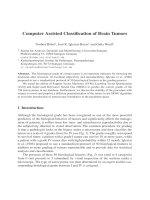
at the entrance of each room), shown in Fig. 1.1.a and Fig. 1.1.b. All of
them have been automatically learnt by the system, with very little human
intervention (only several training images, with the landmarks to learn
marked, must be provided).
The deformable model carries the landmark information inside it, so this
information is adapted to the model’s deformation and can be used to
evaluate the model fitness. This is achieved using a genetic algorithm,
1 Learning Visual Landmarks for Mobile Robot Topological Navigation 3
where each individual represents a deformed model. The population then
explores the image during its evolution. The genetic search algorithm is
able to handle landmark’s perspective deformation problems. The second
relevant aspect is the system capacity for reading text or icons inside
landmarks designed for human use, such as those shown in Fig. 1.2, so the
system can be used to find and read signs, panels and icons in both indoor
and outdoor environments. This allows the robot to make high-level deci-
sions, and results in a higher degree of integration of mobile robotics in
everyday life. Various experimental results in real environments have been
done, showing the effectiveness and capacity of landmark learning, detec-
tion and reading system. These experiments are high-level topological
navigation tasks. Room identification from inside, without any initializa-
tion, is achieved through its landmark signature. Room search along a cor-
ridor is done by reading the content of room nameplates placed around for
human use; this allows the robot to take high-level decisions, and results in
a higher integration degree of mobile robotics in real life. Finally, although
the presented system is being tested for mobile robot topological naviga-
tion, it is general enough for its direct use in a wide range of applications,
such as geometric navigation, inspection and surveillance systems, etc.
c)
d)
f)e)
Fig. 1.1. Some of the landmarks learned
4 M. Mata et al.
The structure of this chapter is, following this introduction, a brief state
of the art concerning actual work on mobile robot navigation. Then an
overview about deformable models, and how they are used in the core of
the landmark learning and recognition system, is described. It is followed
by introducing how to learn new landmark’s parameters; after that, the
landmark detection system structure is presented. Once the system is de-
scribed, its application to a mobile robot and several experimental results
are presented, and also a practical study of the system’s limitations. The
chapter concludes with the relevant conclusions and future work.
Fig. 1.2. Landmarks with iconic information used for topological navigation
1.2 State of the Art
Autonomous mobile robots are currently receiving an increasing attention
as well in the scientific community as in the industry. Mobile robots have
many potential applications in routine or dangerous task such as operations
in a nuclear plant, delivery of supplies in hospitals and cleaning of offices
and houses [30]. A mobile autonomous robot must have a reliable naviga-
tion system for avoiding objects in its path and recognizing important ob-
jects of the environment to identify places in order to understand the sur-
rounding environment. A prerequisite for geometric navigation of a mobile
robot is a position-finding method. Odometry is the most used localization
method for mobile robot geometrical navigation. The problem is that the
accumulation of small measure errors will cause large position errors,
which increase proportionally with the distance traveled by the robot.
Wheel slippage and unequal wheel diameters are the most important
source of error [11]. As a mobile robot moves through its environment, its
actual position and orientation always differ
from the position and orienta-
tion that it is commanded to hold. Errors accumulate and the localization
uncertainty increases over time.
1 Learning Visual Landmarks for Mobile Robot Topological Navigation 5
An alternative approach is topological navigation. It allows overcoming
some of the classical problems of geometric navigation in mobile robots,
such as simultaneously reducing the uncertainty of localization and of per-
ception of the environment [42]. On the other hand, topological navigation
is heavily dependent on a powerful perception system to identify elements
of the environment. Chosen elements for recognition, or landmarks, should
be simple enough to allow an easy identification from different view an-
gles and distances.
Visual recognition is the problem of determining the identity and posi-
tion of a physical element from an image projection of it. This problem is
difficult in practical real-life situations because of uncontrolled illumina-
tion, distances and view angles to the landmarks. Machine learning tech-
niques are being applied with remarkable success to several problems of
computer vision and perception [45]. Most of these applications have been
fairly simple in nature and still can not handle real-time requirements [8,
31, 37]. The difficulty with scaling up to complex tasks is that inductive
learning methods require a very large number of training patterns in order
to generalize correctly from high density sensor information (such as video
cameras). However, recent results in mobile robot learning have demon-
strated that robots can learn simple objects to identify from very little ini-
tial knowledge in restricted environments [9, 21, 23, 33].
There are two major approaches in the use of landmarks for topological
navigation in related literature. One approach uses as landmarks regions of
the environment that can be recognized later, although they are not a single
object. Colin and Crowley [12] have developed a visual recognition tech-
nique in which objects are represented by families of surfaces in a local
appearance space. In [4] a spatial navigation system based on visual tem-
plates is presented; templates are created by selecting a number of high-
contrast features in the image and storing them together with their relative
spatial location. Argamon [2] describes a place recognition method for
mobile robots based on image signature matching. Thompson and Zelinsky
[47] present a method for representing places using a set of visual land-
marks from a panoramic sensor, allowing an accurate local positioning.
[19] has developed a vision based system for topological navigation in
open environments. This system represents selected places by local 360º
views of the surrounding scenes. The second approach uses objects of the
environment as landmarks, with perception algorithms designed specifi-
cally for each object. In [10] a system for topologically localizing a mobile
robot using color histogram matching of omni directional images is pre-
sented. In [44], images are encoded as a set of visual features. Potential
landmarks are detected using an attention mechanism implemented as a
6 M. Mata et al.
measure of uniqueness. [6] describes a series of motor and perceptual be-
haviors used for indoor navigation of mobile robots; walls, doors and cor-
ridors are used as landmarks. In [27] an indoor navigation system is pro-
posed, including the teaching of its environment; the localization of the
vehicle is done by detecting fluorescent tubes with a camera. However,
there are still few practical implementations of perceptual systems for
topological navigation.
1.3 Deformable Models
Much work has been done in visual-based general object detection systems
in the last decades, with encouraging results, but only a few systems have
been used in practice, within uncontrolled real-world scenes. Furthermore,
most of the systems are based on hand-made object representations and
searching rules which difficult system adaptability. There is a need for
general and practical object detection systems that can be adapted to diff-
erent applications quick and easily. This need for practical systems inexo-
rably leads to some restrictions, usually opposed to generality require-
ments:
1. Computation time cannot exceed usability limits. Although the proposed
system is general enough for handling general 3D objects, time restric-
tions obligates to particularize for planar objects, or single faces of 3D
objects. However, the system is designed for, and can be easily extended
to, 3D object detection if desired.
2. Flexibility and generality points toward general systems which can learn
and use new objects with minimal human intervention.
3. Robustness is encouraged by the learning ability. No learning can take
place without a certain evaluation of its performance.
The proposed particularized system maintains enough generality to cope
with the detection of nearly any planar object in cluttered, uncontrolled
real images, in useful times, by only software means. It uses a simple but
effective representation objects by means of deformable models, and is
easily
adaptable to detect new objects by training from images, with mini
mal human intervention (only marking the object to learn in the training
images).
1 Learning Visual Landmarks for Mobile Robot Topological Navigation 7
1.3.1 Related Work
Deformable models have been intensively studied in image analysis
through the last decade [13, 55], and are used for detection and recognition
of flexible or rigid models under various viewing conditions [7]. They
have been applied for querying a database given the object shape, color
and texture [54]; motion-based segmentation of deformable structures un-
dergoing nonrigid movements through shape and optical flow [24]; for In-
telligent Vehicles, they have been used to detect road signs [7, 17], vehi-
cles [56] and road borders [25]; after the work of [55], they are commonly
used for human face detection and tracking [20, 28]; recognizing charac-
ters and lineal symbols in handwritten line drawings [49, 50, 52]; in medi-
cal imagery they have been used for the segmentation of deep brain nuclei
in 3D MRI [39], cell segmentation [29] or human melanoma cancer cells
in confocal microscopy imaging [41].
As noted in [14], a global shaped model based image segmentation
scheme consists of the following blocks:
1. The initial model, M, a model with a fix area, located in the center of the
image.
2. The deformable model M(Z). This model is obtained from de previous
one through the deformation parameters, Z. They can be position, hori-
zontal and vertical scale, rotation and additional deformation parameter.
3. The likelihood probability density function, p(I|Z), that means the prob-
ability of the deformation set Z occurs in the image I.
4. A search algorithm to find the maximum of the posterior probability
p(Z|I).
In a latter stage, if the detected object contains symbolic information –
like text or icons-, it is interpreted using an empirically selected neural net-
work-based classifier.
Potential fields of application are mobile robotic (landmarks in naviga-
tion tasks), industrial robotic (object detection and handling), driving assis-
tance systems (traffic signs, road informative panels, vehicle detection)
and industrial tasks (object detection and inspection, tag reading).
8 M. Mata et al.
Various works on human cognition points that humans use view-point
based object representations rather than object-centered ones [15, 46]. This
is the focus used in some approaches to object detection and representation
issues, like appearance and combination of views [22, 43, 51]. Model-
views of objects are a simple but rich way of representing objects, but it
has a major drawback in the sense of object aspect changes with perspec-
tive and illumination.
In the proposed system, illumination changes are handled using an ade-
quate color representation system, while perspective-related aspect
changes are coped with the use of deformable models.
(a) (b)
1.3.2 Deformable Model
The proposed deformable model is a very basic geometrical figure, a 3D
parallelepiped whose only mission is bounding or enclosing the considered
object, independently of its type or shape (Fig. 1.3.a). The geometrical pa-
rameters of the deformable model must follow the object aspect changes
with perspective. Then, some kind of detail (object-specific data) has to be
added over the basic deformable model in order to distinguish one object
from another and from the background (Fig. 1.3.b). The only restriction
here is that this detail will have to be used in a way that allows following
model’s deformations. So each object is represented by a set of specific de-
tails, which can be “glued” to a general deformable model. The object
search is then translated to a search for the deformable model parameters
that makes the details to match with the background.
For a practical 2D case, the deformable model needs 6 degrees of free-
dom (d.o.f.) to follow object translations and rotations, and some perspec-
tive deformations, as
shown in Fig. 1.4. Object translation in the image is
Fig. 1.3. (a) Basic deformable model, and (b) object-specific added detail
1 Learning Visual Landmarks for Mobile Robot Topological Navigation 9
covered by the (X, Y) d.o.f. of Fig. 1.4.a, representing the pixel coordi-
nates of the reference point for the model (the upper left corner). Object
scaling (distance from the camera) is handled with the pair ('X, 'Y), as
shown in Fig. 1.4.b. The parameter D from Fig. 1.4.c manages object rota-
tion. Finally, object skew due to affine perspective deformation is only
considered over the vertical axis, heavily predominant in real images; the
general skew along the vertical axis can be decomposed as the combina-
tion of the basic deformations illustrated in Fig. 1.4.d and Fig. 1.4.e. In
practice, only the component in Fig. 1.4.e, measured by the d.o.f. SkY, is
frequent; the deformation in Fig. 1.4.d is only dominant for relatively large
and narrow objects and when they are at the same vertical level of the op-
tical axis. These simplifications of the perspective distortions could be eas-
ily avoided, but they provide a reduction of the number of degrees of free-
dom considered, saving computation time with little impact on real scenes,
as will be shown later.
X
Y
(x ,y)
'
x
'
y
D
(a) (b) (c)
SkY
(d) (e)
Fig. 1.4. 2D degrees of freedom for the basic deformable model. (a) traslation,
(b)scaling, (c)rotation, (d)–(e) skew by perspective deformation
These six degrees of freedom are valid for planar objects. When consid-
ering 3D objects, more degrees of freedom must be added. In the proposed
approach, only two new ones are needed, the pair (X’, Y’) with the pixel
coordinates of the frontal side of the 3D deformable model (Fig. 1.5.a),
covering object displacements over the plane parallel to the image and ro-
tations over the vertical axis.
Rotations that are not covered by D
••X’, Y’ can
be handled without adding any other d.o.f., simply by allowing the 'Y and
10 M. Mata et al.
'Y parameters to be negative. The effect of a negative value of 'X is
shown in Fig. 1.5.b, while a negative 'Y is shown in Fig. 1.5.c.
Of course this set of 8 d.o.f. does not cover precisely all possible per-
spective deformations of an object, but they allow to approximate them
enough to recognize a generic object if adequate added details are used,
and provides a reduction of the parameter search space.
(x ,y)
(x’ ,y’)
(x ,y)
(x’ ,y’)
(x ,y)
(x’ ,y’)
(a) (b) (c)
Fig. 1.5. 3D-extension degrees of freedom for the basic deformable model
The detection of the object is now a search process in the model’s pa-
rameter space, comparing the detail added to the model with the back-
ground in the place and with the size and deformation that the parameters
determine. Two reasons make this a complex search: the high dimensional-
ity of the search space (8 d.o.f.), and the comparative function between the
added detail and the background. This comparative (or cost) function is not
a priori predefined, and it can be very complex and not necessarily a para-
metrical function.
Genetic evolutionary algorithms have shown to be a very useful tool for
these kinds of search processes [26, 53]. If the deformable model’s geo-
metric parameters are encoded into the genome of the individuals from a
genetic algorithm, each individual become a deformable model trying to
match the desired object through the image. The fitness function for each
individual is the perfect place for doing the matching between the model’s
added detail and the background (the cost function). A classical genetic al-
gorithm (GA) is used to make the search in model parameter space, with
standard binary coding, roulette selection, standard mutation and single-
point crossover. Single individual elitism is used to ensure not to loose the
best individual. No optimization of the GA code, or evaluation of other GA
variants, has been done yet, it is one of the pending tasks to do, so the
search still can be speeded up considerably. One consideration has been
taken into account for achieving small enough computation times to make
the system of practical use: a proper GA initialization is used to speed up
1 Learning Visual Landmarks for Mobile Robot Topological Navigation 11
the convergence. If the initialization is good enough, GA convergence is
extremely quick, as will be shown.
1.3.3 General Scheme
There is a large collection of 2D pattern search techniques in the literature
[40]. In this application, a classical technique is used: normalized correla-
tion with an image of the pattern to be found (usually named model). The
advantages and drawbacks of this technique are well known. Its strongest
drawback is its high sensitivity to pattern aspect changes (mainly size and
perspective), which makes this method unpractical in most cases. A two
step modified method is proposed for overcoming this problem. First, in a
segmentation stage, relevant regions in the image are highlighted; then the
regions found (if any) are used for initializing the genetic pattern search
process. The main problems when trying to detect objects that humans use
as landmarks is perspective deformation and illumination. Object aspect
changes in the image with distance and angle of view, and under different
illumination conditions. Deformable models are used to handle perspective
deformations, and HSL color space and real image-based training cope
with illumination.
As an overview, objects are represented as a basic deformable model
that encloses the object, plus some specific detail (“glued” to the basic
model) to distinguish and recognize objects. Eight degrees of freedom are
considered for the deformable model to follow with sufficient approxima-
tion all object aspect changes with relative position, distance and perspec-
tive. These model parameters are encoded as the genome of individuals
from a genetic algorithm’s population. Object search is a search in the
model parameter space, for the set of parameters that best matches the ob-
ject-specific detail to the image in the location they determine. This com-
parison between model’s added detail and the background is then the fit-
ness function for the GA individuals (deformed models). The only
restriction to the fitness function is that deformed models that better
matches the desired object in the image should have associated higher fit-
ness values.
Before starting the GA search, it is a good idea to properly initialize the
algorithm, in order to decrease the usually long convergence times of evo-
lutionary algorithms; the way used to select the regions of interest (ROI)
can be nearly anything. And once the algorithm has finished, if the object
has been found in the image, some useful information must be extracted
from it. This working line leads to a three stage structure for the object de-
tection system: initialization,
object search, and information extraction, as
12 M. Mata et al.
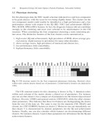
shown in Fig. 1.6. In order to speed up landmark detection, a three-stage
algorithm is used. First, regions of interest (ROI) are extracted. Then, ex-
tracted ROI are used to initialize a genetic algorithm (GA) for the land-
mark search through the image. Each individual of this GA encodes a de-
formable model. The fitness of an individual is a measure of the matching
between the deformed model it encodes and the landmark searched for. Fi-
nally, if a landmark is found, symbols are extracted and identified with a
classical backpropagation neural network.
Stage I
Regions of
Interest (ROI)
selection
Stage II
Evolutionary
object search
Stage III
Information
extraction
Initialization
objects found
listing
- G.A. population initialized
over relevant zones.
- open methodology.
- speeds up stage II.
- deformable model-based search with a G.A.
- Each G.A. individual is a deformed model
instance.
- open methodology to evaluate the matching
between model and object (fitness function).
- Geometrical properties.
- Symbolic contents
interpretation (if needed).
Fig. 1.6. Three stage structure of the proposed object detection system
For the learning process, the human teacher must provide several training
images, where the object or landmark to learn is bounded by rectangular
boxes (this boxes will be referred to as target boxes in the rest of the chap-
ter). There are no a priori restrictions for the training set provided. How-
ever, the wider the conditions this set of images covers (illumination,
background, perspective distortions, etc), the best results the learned pa-
rameters will achieve on real situations.
As the recognition process, it can be sequentially divided in two steps:
candidate hypotheses generation (through color ROI segmentation) and
hypotheses verification or rejection (with the genetic search). Cons-
equently, the learning process for a new landmark is also divided in two
stages. In the first step, thresholding levels for HSL segmentation are
found. The second step is dedicated to determine the location of the corr-
elation pattern-windows inside an individual.
1.4 Learning Recognition Parameters for New Objects
1 Learning Visual Landmarks for Mobile Robot Topological Navigation 13
Any method to segment regions of the image with good probabilities of be-
longing to the selected object can be used here. After several trials, the use
of object’s color information to generate regions of interest was decided.
Color vision is a powerful tool to handle illumination related aspect
changes of the objects in the image. After evaluating different color spaces
(RGB, normalized rgb, CIE(L*a*b*) and HSL) , HSL space (Hue, Satura-
tion and Luminance) has been selected as the system base space (Fig. 1.7).
R
G
B
White
Black
Hue
Lum.
Grey Scale
Sat.
Fig. 1.7. Cylindrical interpretation of HSL space
According with [38], HSL system presents some interesting properties:
1. Hue is closely related to human color sensation as specifies the “percep-
tual” color property of the considered pixel. Many objects have colors
selected to be easily distinguishable by humans, especially those suited
to carry symbolic information inside. Furthermore, this component is
heavily independent of illumination and shadows.
2. Saturation indicates the “purity” or dominance of one color as it indi-
cates how much of the particular color does the pixel have. Another
meaning is how far from gray scale is the pixel because the gray scale,
from black to white, has saturation equal to zero (it has the same amount
of all colors). This component is somehow insensible to moderate
changes of illumination.
3. Luminance takes into account all illumination information of the scene;
the L component is the black-and-white version of the scene as it meas-
ures the amount of light which has arrived at each pixel.
1.4.1 Parameters for ROI Extraction
14 M. Mata et al.
On the other hand, Hue presents some drawbacks. First, it is an angular
component, so the values 0 and 256 are exactly the same (circular continu-
ity); this must be taken into account when segmenting a color interval.
Second, Hue is not defined for low or null values of saturation; in these
situations, the pixels are achromatic, and Hue can take erratic values. The
first issue is easy to overcome segmenting in two steps, but the second one
requires a more complex treatment. In this work, the 255 value for Hue is
reserved and labeled as achromatic. Hue component is rescaled to 0-254,
and pixels having low saturation are set to the achromatic value. For the
rest of the processes, when a pixel is set as achromatic, only L component
is used for it. Let any HLS color image, sized Xd x Yd pixels, be I(x,y):
>
>
YdyXdxyxSyxLyxHyxI ,0,,0,,,,,,,
(1)
A simple and effective way to generate object-dependant ROI is to se-
lect a representative color for the object, and segment image regions hav-
ing this color. In order to handle intra-class color variations in objects, as
well as luminance effects, a representative color interval is learned by the
system for each class of objects to detect, defined by
LLSSHHCI 'r'r'r ,, (2)
The color segmentation is made in H, S and L components of the image
I(x,y) separately, and combining them with an AND logical operation,
leading to binary image B(x, y):
^`
^`
^`
°
°
¯
°
°
®
'dd'
'dd'
'dd'
otherwise
SSyxSSS
LLyxLLL
HHyxHHH
yxB
0
,AND
,AND
,
1
,
(3)
Segmentation is done by thresholding in a corrected HLS space fol-
lowed by some morphologic transformations. In the first training step, the
system has to learn the best threshold values for the segmentation of the
landmark. Upper and lower thresholds for Hue, Saturation and Luminance
components are estimated. This six values (G=5) are made to compose the
genome of the individuals of a new GA, used for searching through the
training image color space: [C
0
]=H, [C
1
]='H, [C
2
]=L, [C
3
]='L, [C
4
]=S,
[C
5
]='S.
The fitness function for this GA must encourage the segmented regions,
generated by each individual, to match the target boxes defined in the N
T
training images. Each training image I
T
n
(x,y), n[0,N
T
), will contain t
n
tar-
get boxes A
n
j
, j[0,t
n
]. On the other hand, segmented regions outside the
1 Learning Visual Landmarks for Mobile Robot Topological Navigation 15
target boxes are not desirable. The ideal segmentation result should be a
binary black image with the target boxes corresponding zones in white,
B
T
n
(x,y):
¯
®
otherwise
tjAyx
yxB
n
n
j
n
T
,0
1,,0,,,1
,
!
(4)
This “ideal image” can be matched with the binary image resulting from
an individual's genome [C]
i
, (B
i
n
(x, y, [C]
i
), calculated with equation (3)
with the thresholds carried in [C]
i
), using a pixel-level XOR logical func-
tion. Pixels that survive this operation are misclassified, since they have
been included in segmented regions while they do not have to (or the other
way around). The number of white pixels after the XOR pass is then a use-
ful measure of the segmentation error for the considered training image.
The total segmentation error for one individual is obtained by repeating
this operation for all the training image set, and accumulating the misclas-
sified pixels in each image:
>@
>@
¦¦¦
»
¼
º
«
¬
ª
1
0
1
0
1
0
,,XOR,
1
T
N
n
Xd
x
Yd
y
k
i
nn
T
T
i
CyxByxB
N
CE (5)
The fitness function is then chosen as an inverse function of this total er-
ror.
Target
Outer
regions
Inner
regions
Target
Outer
regions
Inner
regions
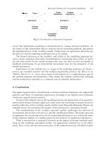
Fig. 1.8. Regions used for LDH calculation
Before the learning search starts, a coarse initialization of the GA is
done for decreasing search time. A set of initial threshold H, L and S val-
ues are obtained from any of the training images using local histograms.
Two sets of histograms for H, L and S are computed from the inner and
outer regions adjacent to the target box boundaries (Fig. 1.8). Inner histo-
grams contain information from the object, the background and noise.
16 M. Mata et al.
Outer histograms contain information from the background, other objects
and noise. For each component, the outer histogram is subtracted from the
corresponding inner histogram, with negative resulting values forced to
zero. The resulting Local Difference Histogram (LDH) will contain only
information belonging to the desired object and not present in the outer re-
gions. Initialization values are taken from a peak search over the LDH.
This way several values for H, L and S thresholds are estimated, and
their possible combinations generate a good part of the GA's initial popula-
tion. The rest of the population is randomly generated. This initialization
speeds up considerably the training process; training time is of the order of
five seconds per training image. Fig. 1.9 shows learned segmentations for
different objects.
(a) (b) (c)
Fig. 1.9. Learned segmentation examples: (a) pedestrian crossing traffic sign, (b)
highway informative panel, c) room informative panel
The color interval learning stage makes unnecessary color camera cali-
bration, since thresholds are selected using images captured by the same
camera. However, if a new camera needs to be used with an object data-
base learned with a different camera, it is enough to make a coarse color
adjustment by any approximate method.
In order to accomplish practical processing times, one new particulariza-
tion has been made to the system. Many of everyday objects are planar, or
its third dimension is small compared to the other, and many of 3D objects
has nearly planar faces that can be considered as a separate planar objects.
1.4.2 Parameters for Evaluation of the Fitness Function