Mechatronic Servo System Control - M. Nakamura S. Goto and N. Kyura Part 2 docx
Bạn đang xem bản rút gọn của tài liệu. Xem và tải ngay bản đầy đủ của tài liệu tại đây (718.72 KB, 15 trang )
1.1E
mergence
of
Mec
hatronic
Serv
oS
ystems
5
as faraspossible.Thatistosay ,the motormust be selected from the
clearly discussed results on thenecessary maximaltorquefor executing
op eration.Inaddition, the size of continuouslymixed disturbance must
be belowthe continuous rated torque of motor.
5. In manyservosystems, afeedbacksystem can be only established based
on theinformation of servoactuator, butnot according to the information
of eachmoveable tipormotion tip. It meansthat, the detectorofposition
andvelocityinthe opposite loadside of motor(side without load) is
installed and thenthe feedback system of actuatorcontrol is resembled
by
the
obtained
information.
This
kind
of
con
trol
system
is
called
as
emi-
closed
lo
op.
Generally
,i
ti
sv
ery
difficult
to
construct
the
feedbac
ks
ystem
by motiontip informationinmanymechanism machines. The structureof
afull-closedlooponthe feedback of moveable tipinformation adoptedin
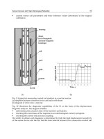
some parts is shown in Fig.1.3. In addition, almost all mechanic structures
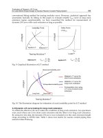
of industrial six-freedom degree robots are semi-closed loop. The relation
with servoactuator is briefly shown in Fig.1.4. The structureofthis kind
of semi-closed loop cannotbeobtainedinthe mechatronic servosystem as
same as the general feedbacksystem. Fortaking into account the system
as same as the general feedbacksystem, the condition is that the system
should be rigidlyunifiedwith the actuatorwhen mechanismiswithin the
control region according to the desired motioncommand.
6. Theactuator installed in the mechanism structured for multi-axis move-
able mechanismgener ally corresponds to the forward motionofone actua-
toraswell as rotationofone axis(freedomdegree). The arbitrary curve in
three-dimensional space implemented by simultaneous control of multiple
axes is given in aservosystem as the command of time function about
the position for desired motionineachindependent axis. Theprecondi-
tion in control system is that axisisregarded as independence. In fact,
for example, in the case of amulti-axisrobot arm, thereactionofone axis
motion affectsother axes, i.e., axis interference occurs. This axis interfer-
ence is very important when tryingtominimize it in mechanism design.
Moreover, in amechatronic servosystem, when considering one axis, the
effect fr om other axes duetoits reaction is regarded as the disturbance.
D e t e c t o r
Actua t o r M e c h a nis mpa rt
U pper c ontroller
S e rvodr i v e r
Fig. 1.3. Structure of industrial servosystem
61
Outline
of
Mec
hatronic
Serv
oS
ystems
Fig. 1.4. Structure of industrial robot and arrangementofactuator
And forreducing the effect in control to aminimum, the motionofaxis
should be changed as be capable of independence.
7. The generationofobjectivereference input for realizing mechanism move-
mentstructured with amulti-axismechanism is by the servosystem in
whichthe independentmotion of eachaxis includingintro ducedmachine
mech
anismc
an
be
realized.
The
featureso
fr
eference
input
is
regulated
for
keepin gthe consistenceofeachaxis. In almost all cases, position control
system is regarded as a1st order system. The feedforward gain should be
iden
tical.
If
regulating
lik
et
his,i
ti
sv
ery
easy
to
implemen
tt
he
algorithm
of referenceinput generation to amulti-axisservosystem for anyspatial
curve.
8.
Fo
rr
ealizing
an
arbitrary
curve
in
three-dimensional
space,
in
most
of
cases,the curveisapproximatedbyafoldedline. As its results, the refer-
ence input to eachaxis servosystem is renewed in eachgiven co ordin ate
po
in
ta
nd
the
ramp
input
with
va
rious
slop
ea
nglesi
sg
iv
en
con
tin
uously
.
The velocityofeachaxis is calculated for making the given synthetic
velocityasadesiredvelo city. In addition, in the case of performing the
acceleration/deceleration control at start/stop point, the reference input
for simultaneous start/stop of all axes, i.e., same command to eachaxis
at acceleration/decelerationpoint, is generated.
9. Thedata regarded as objective referenceinput to servosystem from the
uppercontrol device, suchascomputerorspecial control, should be given
according to the designatedperiod(designatedtime interval). Therefore,
the
reference
input
for
serv
os
ystem
is
describ
ed
with
the
form
of
av
elo
cit
y
1.2I
ssues
in
Mec
hatronic
Serv
oS
ystems
7
command.Here, the periodofthis commandortime interval is called as
the system clock of theservosystem in the controller or servodata rate of
thecontroller.Since this reference time interval is selected based on the
prop ertyofthe servosystem dependentonthe mechanismpartstructure
and related with the capabilityofcontrol devise, itsvaluerepresents the
synthetic performance of amachine.Inthe numerical control device of
aworking machine, several [ms] as well as ten and several or several ten
times [ms] are adopted.
The knowledge of industrial expects cannot be understood definitely.
Therefore, so far, the theoretical analysisonthe properties of thecontrol
system
structure,
as
we
ll
as
the
va
rious
prope
rties
of
mech
atronic
serv
os
ys-
tem taking into accountits utilization, as above,cannotbefound. Forthis
purpose ,inthis book, stepping on theutilizationofmechatronic servosystem,
various adoptedcontrol methodsand realizedcontrol performancesbythese
methods are firstly discussedtheoreticallyorarguably as themain point, and
then the discussion on the developmentinthe future is added.
1.2Issues in Mechatronic ServoSystems
In or der to understand the current mechatronic servosystem and develop
serv
os
ystems
with
be
tter
pe
rformance
thana
tp
resen
t,
thiss
erv
os
ystem
must be investigated from various points of view. The discussion points are
listed as below.
1. Modelin gofamechatronic servosystem
2. Performance of oneaxis in amechatronic servosystem
3. Performance of multiple axes in amechatronic servosystem
4. Command to servosystem
The above viewpoints come from the system components of servosystem
in theory.Itmeans that aservosystem is one of the system components for es-
tablishingamechanism machineand needed to knowthatinwhichstep servo
system can be thoughtasgood enough so that the system is constructed effi-
ciently,desired mechanism as well as performancesisrealized, etc. Therefore,
the description sequence of subsequentchapters is different fromthe expla-
nation sequence in this chapter. Each section is divided by the items listed
above.
1.2.1 Discussion on ModelingofaMechatronicServoSystem
From theview of usingthe model of mechatr onic servosystem, this model
should be dividedintotwo points. One is the model with the servosystem not
only taking into accountthe mechanismstructurebut alsothe load.Another
is
the
mo
del
comb
iningt
he
mo
deled
mech
anisms
tructurea
nd
serv
os
ystem.
81
Outline
of
Mec
hatronic
Serv
oS
ystems
Forthe mechanismperforming orthogonal motion, various discussionscan be
carried out only by the former modeling. But for the machineasanarticulated
robot, the latter modelingisalso necessary.
(1) Modelingofthe Overall MechatronicServoSystem
In the mechatronic servosystem adopted in anymechanism, suchasanumeri-
cal control working machine, industrial robot, etc., representing the ind ustr ial
mechanism machine, the propertyofprevious or presentservosystem can be
expressed by K
p
.Ingeneral, the value of K
p
is the high rigid of huge ma-
chine. In the general rotation plate, machinecenter, etc, the value of K
p
is
35–40[1/s]. In an industrial robot, the value of K
p
is 15[1/s]. It is naturally
the most simple approximation1st order system in control system. However,
concerning the mechatronic servosystem, it should be considered whichcon-
ditions must be satisfied in its internal structure, and additionally,itisnearly
not clear about the usageconditionofthis 1st order delay system. Actually,if
the maximalspeed used in this machineisabout 1/10 speedregion, this ap-
proximationcan model the whole system quite well. However, if it is number
for one speed, it will have big deviation with theactual system.
In analyzing the currentservosystem, the mechanism is thoughttocom-
bine with shaft of motor whichisasrigid. Under this pr econdition, the servo
motorfor adriving mechanismisselected. The control parameter regulation
of suchaservosystem is also followingthis consideration.Therefore, the 1st
order approximation with preconditionispursuedtobeclarified
[4
]
.However,
in fact,itisdifficult to satisfy this precondition duetovariousrestraints.
High-speed and high-precision motionofmechatronics machines has been the
objectiveinrecentyears. Forfinding outthe controlstrategy,itisrequired to
mo
del
con
trol
system
correctly
.
Concerning about this problem, it is explained in 2.1 and 2.2.
(2)
Mo
delingo
fa
Multi-Join
tedR
ob
ot
Generally, in the multi-jointed industrial robot, orthogonal motion(in working
coordinate)data is generatedbyusing coordinate calculationbasedoninverse
kinematics.B
yt
he
serv
os
ystem
for
join
ta
ngle
cont
rol(
in
join
tc
oo
rdinate),
the motion can be realizedinworking coordinate system as theorthogonal co-
ordinate system.The inverse kinematics calculation of orthogonal coordinate
va
lue
is
pe
rformeda
te
ac
hr
eference
input
time
in
terv
al.
When given two points for performing orthogonal motion,with high-speed
motion, the phenomenon of deviation of several millimeters in the motion
trajectory of the line between two points is apparent. The motionvelocityof
this time is about 1[m/s]. The reference input time interval of robot controller
is generally adopted with about 20[ms]. This velocityislowerthanthe velocity
of appearing centrifugal force rated with two times velocityfor general issue
or collision ratedwith two axesvelocityintegral. Ther efore, the trajectory
1.2I
ssues
in
Mec
hatronic
Serv
oS
ystems
9
deviation is difficulttoconsider basedontheseeffects. But if lengthening the
reference input time interval or whether or not orthogonal motionhappening,
severalreasons should be considered.
When the velo cityofpresentcontourcontrol is below25[m/min], the tra-
jectory deviation does notoccur.Therefore, in the controlbasedonthe previ-
ousposition decisioncontrol concept, the trajectory precisioncan be required.
In the position decision control, the motion with the highest velocityallowed
by this robot can be performedinalmost all cases. In the actual examples of
these kindsofapplication,suchashard-cutting,spot-welding, etc, the posi-
tion
va
riation
(tra
jectory
precision)
is
seve
ral[
mm].
Recen
tly
,t
he
follow
ing
is
also
required.
In order to analyze the control strategy for satisfying these requirements,
the correct modelingfor multi-jointed robot is needed. The relevantdetail
description is given in section 2.3.The discussedmodeling combining the
modelingofthe whole servosystem in the former part, the importance of
modelingcontrol system in future mechanismmachinesisillustrated.
1.2.2Discussion on the Performance of One AxisinaMechatronic
ServoSystem
In ausual, mechatronic servosystem consists of multi-axis mechanism. When
taking into accountthe performance of amechanism machine, the analysis
on
mu
lti-axis
serv
os
ystem
mu
st
be
carried
out.
Ho
we
ve
r,
the
structure
for
thisactuator is basically independentfor oneaxis. Forthe basicfeature of
amechatronic servosystem, the discussion based on the state of one axis
structurei
ss
ufficient
.
Hence, thereare two problems on discrete time interval when analyzing the
oneaxis performance of mechatronic servosystem. One is that the structureof
curren
tm
ec
hatronic serv
os
ystems
are
almost
all
soft
wa
re
serv
os
ystems
and
they must be thoughtofcomi ng fromthe sampling controlsystems. Therefore,
the data renewal time interval of control system is determined by sampling
frequency
.I
ng
eneral
mec
hatronic
serv
os
ystem,
theree
xist
same
dela
yt
ime
and 0th order hold with this time interval. Therefore, this time interval greatly
affects the characteristicofclosed-loop control system.
Another is that, the uppercontroller seen fromthe servosystem, i.e., the
computerusing for internal trajectory calculationofthe controller, is per-
formedinatime interval providingcommandgiven in the servosystem. From
therelationbetween this time interval and performance of thecontrol system,
theoverall mechatronic servosystem performance of amechatronic machine
can be determined. From this pointofview, the value of these discrete time
intervals are very important foranalyzing the performance of amechatronic
servosystem.
10
1O
utline
of
Mec
hatronic
Serv
oS
ystems
(1)Proper Sampling Frequency
In themiddle of 1980s, microprocessor (CPU), i.e., digital signal processor
(DSP)became cheaper. These processors are equippedintoclosed-loop of
servosystem. Hence, servosystem is constructed and movementcan be re-
markably flexible. Software servosystems were developed.
Theseservosystems were developed in thelaboratorybelonging to one of
authors. From theexperiments, an experience rule, wasobtained. The eigen-
value of position control system usingfor amechatronic machinebasedonthe
realizedsoftware servofromthe analoguevelocityofacontrol device cannot
be overabout 1/30 sampling frequency. Moreover, the velocitycontrol system
is madebythe software servosystem and its insidecan be found similarwith
the analogue pattern.
The great difference herebetween the general sampling control system and
the control system used in the mechanism machineisthe delay time. In the
usually equippedpro cess control, comparing with the sampling time interval,
theconsumedtime for working outthe state input andoperation value can be
neglected. However, in the servosystem of amechanism machine, this cannot
be successful.
If the software servosystem adopted in amechanism machineisthe object
of simulation, various unknown parts areclosed up.How to set the property
of poweramplifier with PWM pattern,and howtocatchthe timing of state
input andthe dynamicofoperation output canbeobtained.
In general, in asoftware servosystem, avery big sampling frequency is
adopted.Namely,under the restraintofhardwarecost,the maximalsampling
frequencyisselected.Indetermining the sampling frequency by this way,the
performance boundary of theservosystem when usingthis frequencyisnot
distinct.Eventhoughexpecting to raise its performance,whichcomponentof
control system should be improvedisalso unknown.
In section 3.1,the quite simpleformofmechatronic servosystem wasana-
lyzed. The relation between the performance of acontrol system andsampling
time interval when considering the utilization situation of aservosystem was
clarified.
(2) Reference Input Time Interval
When considering the characteris ticofamechatronic servosystem as intro-
duced before, andregarding the loop structureofacontrol system about
actuator above investigation of servosystem char acteristicasthe identical
importantitem with its controller design, howtoprovide the commandto
servosystem is aproblem. Thisproblemisabout the form of time functionof
command.The problemofcommandcontaining the way of data given must
be discussed.
In the discussion of this commandsystem, with the currentcontroller
structure, as theitem about the control performance of aservosystem, the
1.2I
ssues
in
Mec
hatronic
Serv
oS
ystems
11
time intervalofgiven data to the servosystem through the interface from the
uppercontroller is expected. Generally,inthe controller of themechanism
machine, the data to the servosystem is given in adesignated period. This
designatedperiodiscalled thereference input time interval. This is also called
the (controller) system clock.
This reference input time interval is discrete width as the data to the servo
system. Within this interval, the command function of eachaxis is calculated.
Then,this calculatedvalueisobtainedinthe servosystem with the state of
zero order hold. From this,the motion of theservosystem generates velo city
pe
rio
dic
va
riation
reliedo
nt
his
time
in
terv
al
andt
ra
jectory
deterioration.
Previously,
the
reference
input
time
in
terv
al
is
obtained
as
the
va
lue
rep-
resenting the controller performance.Atpresent, in the newly developed con-
troller,this value has the trendtobeminimal. However, dominatedbythe
development of themicroprocessor, the desired performance is expected to
be realizedwithout great cost. Therefore, the reasonable explanation of the
relationship between this reference input time interval and various generated
phenomenonisalmost non-existent.
The competition of mechatronic product cost is rapidlyincreased. High
performance is requiredmeanwhile keepingthe current situation. In this sit-
uation, the performance of servodriver unit,the performance of theupper
controller (reference input time interval, etc) as well as the characteristicof
loadare analyzedcomprehensively.Bytaking these performancesobtained
the balance whenobserving these performancesrespectively as the whole, it
is very important to realize these desired performancescomprehensively.As
the first stagefor analyzing them, fromthe view of theservosystem char-
acteristicofone axis, thediscussion on the reference input time interval is
carried out in section 3.2 and 3.3.
(3) Quantization Error and ControlPerformance of Control
System
Thestructureofthe software servosystem wasdeveloped from only the po-
sition controller software to both velocitycontroller andcurrentcontroller
software, fromthe development of utilizedCPS, i.e.,DSP.Inthe construction
of thecontrol system,high response performance is generallyrequired from its
internal minor-loop. In the electric servosystem, currentfeedbackloopisthe
inner-most loop.How resolution of currentdetection is expected for satisfying
the required performance of servosystem is an important item to discuss in
the stageofdesigning hardware constructing servosystem.
As usual, although the control performancesabout the position and veloc-
ityofthe servosystem were clear, the theoretical equationsfor expressing the
designwhichthe controlperformance must be satisfied about its internal is
unknown. In view of theconcretecircu it structure, the discussion of the item
on quantizationerrorisformulated. However, the analysissolution on various
in
ternalp
arameters
relation
to
thec
on
trol
system
structure
is
ve
ry
difficult
12
1O
utline
of
Mec
hatronic
Serv
oS
ystems
to solve. Its difficulty would be estimated by taking into accountthe equation
expression of poweramplifi er of PWM pattern.Fromthis pointofview, in
almost all presentcases, thequantizationscale of control system internal, i.e.,
resolution is determined based on experience.
Here, for the current(torque) loop of the motor, the most internal loop
of mechatronic servosystem, the relationship between the necessary perfor-
mance in the controlsystem and the resolution of currentdetection part is
investigated. In order to clarify the main issue on considering the current
structureofthe mechatronic servosystem, the foreseen whole control system
is
considered
and
the
problems
are
form
ulated.
On
these
problems,
is
discussed
in
ch
apter4
,a
ftera
nalyzing
the
resolution
of position detection firstly in section 4.1,the torque resolution is investigated
in section 4.2.Fromthe formulation illustratedhere, the resolution of torque
command considering velocityvariation ratioasacontrol performance is clear.
According to thisresult, the necessityofidenticalprecisionwith the necessary
resolution in currentdetection is clear. Moreover, in the case of zero-zoneof
poweramplifier, i.e., nonlinear characteristic, it is easytoevaluate that the
high resolution is necessary from the obtained results here.
1.2.3Discussion on the Performance of aMulti-AxisMechatronic
Servo System
The
basic
part
of
on
discussion
on
mec
hatronic
serv
os
ystems
can
be
carried
out as aone-axisservosystem. However, wheninvestigatingthe performance
of mechanismmachines, theymust be investigated as multiple axes. The mo-
tion
of
mu
lti-axis
serv
os
ystems
causing
basic
phenomena
duet
ot
orques
at-
uration can be found. Whenusing aservosystem in the state of one axis,
thereisalmost no problem in the induced phenomenon duetotorquesat-
uration
fromt
he
serv
os
ystem
pe
rformance
po
in
to
fv
iew.
Ho
we
ve
r,
if
this
phenomenon occursinthe multi-axis contour control, it will produce great
effects on servosystem performance.Theseproblems arediscussed in section
5.1
and
5.2.
(1)
To
rque
Saturation
Generally,
in
mec
hatronic
serv
os
ystems,
the
ratio
of
maximalt
orquet
hatc
an
be usedinratedtorqueand acceleration/deceleration is about1:3∼ 5. In actual
servosystems, constantcoulombfriction frommotion resistance occupies a
big part of rated torque when the servosystem is set into the mechanism. It
means that, the opposite force in operation is regarded as the torque load.
In order to allowthesetorques in thecontrol system when performing the
movementalong astraightline, their values are reduced remarkably.Hence,
in contour control, the servosystem must guarantee themovementalong the
straightline. When clarifyin gthe application conditionofthe mechatronic
system,i
tm
ust
grasp
that
in
whic
hs
cale
torque
reac
hes
saturationi
nt
he
1.2I
ssues
in
Mec
hatronic
Serv
oS
ystems
13
state of capable motionofthe mechanismaswell as in whichdegree control
performance deterioratesdue to torque saturation.
Themechatronic servosystem design should select aservomotor forthe
driving mechanisminmanycasesexcept the stageofresearch. Therefore, in
servomotor selection,the velocityprofile (stage form) fordriving is designed
andacceleration/decelerationaswell as constantmotion torquefor designated
parameters (acceleration time,maximal velocity, etc) are calculated. In the
mechatronic servosystem driven by the motorselected as above,itisalmost
impossible to consider clearly the torque reflecting the actual adopted status.
In
section
5.1,fi
rstly
,t
he
measuremen
tm
etho
do
ft
orques
aturation
is
show
n.
Basedo
nt
his
metho
d,
the
torque
saturation
of
thea
ctual
mec
hanism
with the differentstatuses of asingle motorcan be known. Moreover, from
graspingthe occurred phenomenon when existing torque saturationasinthe
ab ove illustration, the reason of actual phenomena can be definitely judged.
Foravoidingtorquesaturation naturally, the actuatorcapable of exporting
torque with big capacity is needed to use. In reality, the correct motionis
more importantthanchanging the ap plication method.For this purpose,itis
necessary to knowthe simpleavoidance method, whichisdiscussed in section
5.2.
(2) Master-Slave Synchronous PositioningControl
Them
aster-sla
ve
sync
hronous
po
sitioning
con
trol
metho
di
st
he
cont
rolt
hat
must satisfy the ratio relationbetween the movementofone axisand that
of another axisbetween two axes. This control is generatedfromthe motion
pe
rformance
requiredi
nt
he
tapping
pro
cess
of
them
ac
hining
cent
er.
In
the
tappingprocess,the 1st axisisthe master axisofthe machiningcenter. This
axis is moving as the control system performing startand stop forstageform
driving
installed
in
the
rotational
to
ols.T
he
transfera
xis
as
the
second
axis
should be traced, namely synchronized. So then it performs aparallel move-
mentasaposition control part. When the tapper, atoolfor standing tap
forr
otation
mo
ve
men
tk
ept
in
the
master
axis,
is
rotated
once,
the
transfer
axis must be movedcorrectone pitch of thespring.Since this correct motion
cannot be guaranteed,the tool calledasoft-tapper is used to keep the tap-
perthroughthe spring andthe synchronous errorofrotation andtransferis
absorbed.
However, since thissoft-tapperisvery expensive, for the decrease of run-
ningcost fortapping,high-precision master-slave synchronous positioning
control is demanded. In themiddle of the 1980s, not only wasthe present
soft-tapper adopted, but alsothe general tapping process wasrealized. At
this time, the rotationtimes of master axis is from 3000 to 4000[rpm].
In order to improve productioninthe future,high-speed master axis ro-
tationnumberisdemanded.For therelevanthigh-level spring, high-precision
master-slave synchronous positioning control is required as well. The relevant
14
1O
utline
of
Mec
hatronic
Serv
oS
ystems
discussion is carriedout in section7.1. In addition, the possibilityofadapt-
ing thismaster-slave synchronous positioningcontrol in contourcontrol is
explainedinsection 7.2.
1.2.4 Discussion on the CommandofMechatronic Servo Systems
Forimproving the motionperformance of the whole mechatronic servosystem,
the methodfor providing the commandtothe servosystem at eachmoment
is avery importantfactor.Itmeans that the final desired motionofcurrent
mechatr onic servosystems should be approximatedfromthe known informa-
tion before the beginning of control. As thepreconditionofuse state of present
servosystem, the revision methodfor theknown commandfor realizing the
desiredmotion is analyzedinchapter6.
(1) Modified TaughtData Method
The contour control for athree-dimensional curveinthe presentindustrial
robot, the curve is approximated by afolded line. In the contourcontrol, the
locus(position) as the form and its motionspeed are the important control
parameters. As usual, the ramp input with adesignated slopefor eachaxis
as its command is introduced.
In
suc
ha
kind
of
rob
ot
pe
rforming
thisc
on
trol,
when
giv
en
three
po
in
ts
and angles are described by aline trajectory,atthe corner part, the trajec-
tory
deviatesf
romt
he
corner
po
in
td
ep
ending
on
the
ve
lo
cit
y.
Certainly
,t
he
ve
lo
cit
yi
sa
lso
decreased.
Fo
rd
ealing
with
this
kind
of
situation,
skilled
op-
eratorofteachingissuccessfully carriedout by given taughtdata variedfrom
the
finaln
eeded
shap
ef
or
eliminating
the
deviation
fromt
he
corner
po
in
ti
n
con
tin
uous
motion.
This
metho
di
si
llustrated
concretely
for
realizing
desired
motionbyrevising commandstoservosystem.
When
approx
imating
ar
ob
ot
armb
ya
1st
order
delay
system
and
assum-
ing
it
as
an
orthogonal
co
ordinate
rob
ot,
concerningt
he
quite
long
straight
line, the theoretical explanation of this phenomenon realizing skilled operator
can
be
easily
carried
out.
Ho
we
ve
r,
it
is
kno
wn
thatt
his
metho
di
sa
lmost
im-
po
ssible
by
the
ab
ove
form
ulation
when
it
is
adoptedf
or
theg
eneral
mu
lti-axis
mechatronic servosystem.
In
sections
6.1,6
.2
and
6.3,t
he
solutiono
ft
he
metho
df
or
impro
ving
the
effective motionperformance by the taughtpointwhichisacircular trajec-
tory butnot lineartrajectory,namely thecomposedtrajectory is given.Here,
taking the taughtpointinformation as thedesired final robot motion, the
analysis solutionfor theissue, that howthe taught pointinformation is re-
visedtobegiven in aservosystem so that the desired motioncan be desired,
is illustrated. The flowchartisexpected to rememberthe solutionwhose roots
must be definitely usedinamechatronic servosystem.
The command methodadoptedinthis book is notonly introducedin
this
ch
apter,
but
alsoc
onsideredf
or
thep
erformance
improve
men
to
ft
he
1.2I
ssues
in
Mec
hatronic
Serv
oS
ystems
15
future mechatronic servosystem. The command metho dtothe servosystem,
considering the properties of mechanism, the features of disturbance size, the
features of process conditions, etc., is regarded as an important item similar
with the servosystem characteris ticimprovementasthe feedback loop.
2
Mathematical ModelConstruction of a
Mechatronic ServoSystem
In this chapter, fromthe view of servocontroller designofmechatronic equip-
ment, suchasanindustrialrobot, NC machine tool, chip mounter, etc, and
stepping on the actionofamechatronic servosystem driven by the signals of a
poweramplifier, the4th order model expressing faithfully the actionobserved
fromthe appearance,the reduced order model simplifying the 4th order model
according to the action conditionand the approximatedlinear 1st order model
in working coor dinate areintroduced.
These modelsare constructed forthe characteristicanalysisofmechatronic
servosystem and the design of servocontroller.The mechatron ic systems
model introducedinthis chapterare the basisofall analysis and design in
the following chapters. Each model is the general linear model in terms of
the form. In the deduction of this equation, the characteristics of theactual
mechatronic servosystem can be expressed correctly with this simple equation
for the first time, according to adopting appropriately the actual restriction
conditions of mechatronic servosystems of the industrial field.
2.1
4th
Order
Mo
delo
fO
ne
Axis
in
aM
ec
hatronic
Serv
oS
ystem
In
the
determination
of
parameters
of
am
ec
hatronic
serv
os
ystem
con
troller,
suc
ha
sp
osition
lo
op
gain
K
p
,velocityloopgain K
v
,etc, as well as in the
discussion of control strategies adopted in the controller; it is necessary to
construct amathematical model expressing the action characteristicofmecha-
tronic servosystem appropriately.Inanindustrialfield, determination of
parameters of the servocontroller is mostlybasedonthe empiricalrule of
practician. There is no mathematicalmodel comprehensively expressing the
mechatronic servosystem includingall mechanism parts, servomotor,servo
controller, etc.
Since
the
structureo
fm
ec
hatronic
serv
os
ystems
in
industryi
st
he
high
order forexpressing all factors, the 4th order model as (2.8), whichretains
M. Nakamura et al.: Mechatronic Servo System Control, LNCIS 300, pp. 17–52, 2004.
Springer-Verlag Berlin Heidelberg 2004
18
2M
athematical
Mo
del
Construction
of
aM
ec
hatronic
Serv
oS
ystem
thenecessary parts taking into accountthe servoproperties in the general
mechanismbyeliminating the unnecessary properties of the servoamplifier
converterinverter, etc, fromthe view of servocontroller design, is proposed.
This 4th order mo del correctly expresses the resp onse characteristicofone
axisofamechatronic servosystem. In the mechatronic servosystem with a
multi-axis structure, this 4th order model can be expressed by combining sev-
eral independentaxes. Forrealizing the expected actioncharacteristicsofa
mechatronic servosystem, the relation between the necessary servoparame-
ters ( K
p
, K
v
)and naturalangularfrequency(ω
L
)ofmechanism part, called
as empirical rule, is K
p
≤ K
v
/ 6. Theappropriation of this equivalent relation
( c
p
=0. 24,c
v
=0. 82) can be theoretically shown in the 4th order mo del. In
addition, by using thismathematical model,the various controlproperties of
themechatronic servosystem can be analyzedand theycan be adoptedin
the design of the servocontroller.
2.1.1 Mechatronic Servo Systems
(1)StructureofanIndustrial MechatronicServoSystem
Fig. 2.1 illustrates the whole structureofamechatronic servosystem. As
shown in this figure, the industrial mechatronic servosystem is the servo
system includingthe mechanism part ,the servomotor driving axis included
in the mechanismpart, theservomotor andthe
servocontroller.Inthis
system,the managementpart managingthe entire mechanismpartand the
reference input generator areseparated. The servosystem of eachaxis is
constructed by the motorpart ,the poweramplifier part ,the current
control part ,the velocitycontrol part andthe positioncontrol part
ands
ensor
(p
ositiond
etector,
ve
lo
cit
yd
etector,
curren
td
etector)
in
order
to
detect the signalfromvariousparts,and connectedwith the mechanism part
by hardware.
.
.
.
Man a gement
p a rt
R efer enc e
input
gener a t o r
M o t o r
M o t o r
P o s i t ion
c ontrol p a rt
P o s i t ion
c ontrol p a rt
V eloc i ty
c ontrol p a rt
V eloc i ty
c ontrol p a rt
C urrent
c ontrol p a rt
C urrent
c ontrol p a rt
P o w e r
c ontrol p a rt
P o w e r
c ontrol p a rt
P o s i t ion signa l
P o s i t ion signa l
V eloc i ty signa l
V eloc i ty signa l
C urrent signa l
C urrent signa l
R e act ion for c e
R e act ion for c e
M e c h a nis m
p a rt
1
st
a x i s
n
t h
a x i s
Fig. 2.1. Industrial mechatronic servosystem structure
2.14
th
OrderM
od
el
of
One
Axis
in
aM
ec
hatronic
Serv
oS
ystem
19
In an industrialmechatronic servosystem, the servosystem of eachaxis
is alwayscontrolled independently (refer to 1.1.2 item 6,7). Actually,the in-
terference or friction of eachaxis is differentaccordingtothe structure of
themechanism part. Although it is possible to design an optimal servocon-
troller corresponding to the various mechanism, thecost of designing aservo
controller respectively for eachmechanism became very highand hencethe
implementation in industry is very difficult. Therefore, fordesigning aservo
system which can be adopted, thisservosystem is combined into eachaxis
corresp ondin gtothe mechanismpar t. That is to say, in an industrial mecha-
tronic
serv
os
ystem,
the
discussion
on
serv
os
ystem
is
carried
out
for
only
one
axis,
be
cause
of
the
imp
ortance
of
the
serv
op
roblemf
or
eac
ha
xis.
If
this one axis problem can be solved, the general industrial mechatronic servo
system problem can be solved, when eachaxis of an industrial mechatronic
servosystem is simply combined and the characteristicinjointcoordinate can
be analyzedapproximately by character isticinworking coordinate by using
nonlinearcoordinate transform between the working coordinate andthe joint
coordinate aboutarticulatedrobot arm.
(2) Servo Controller of IndustrialMechatronic Servo System
The block diagram of servosystem of eachaxis in amechatronic servosystem
is a13th order or higher high-order system strictlyillustrated in Fig. 1.1(refer
to item 1.1.2). From Fig. 1.1, theinformation of locusisnot feedback in the
servocontroller.Fromthis 13th order model,the featuresofmodeling from
the
po
in
to
ft
he
serv
oc
on
troller
of
am
ec
hatronic
serv
os
ystem
is
summarized
as
[4]
:
1. Thepoweramplifier can be obtained linearly whenabig carrierfrequency
is designed greatly;
2.
Thed
ead
zone
of
the
po
we
ra
mplifier
can
be
neglected;
3. Theresonance frequency of axis torque of eachaxis motorisabout 5 ∼ 8
times that of the natural frequency of the mechanism part and can be
neglected
whene
liminating
axis
resonance
by
an
axisr
esonance
filter;
4. The cut-off frequency of the velocitydetection filter and axis resonance
filter can be neglected if it is higher thanthe naturalfrequencyofthe
whole
mech
atronic
serv
os
ystem;
5. The currentcontrol part is designed by considering the balance of the
electric features of motor;
6.
The
po
sition
detection
is
obtained
by
the
logical
calculationo
ft
wo
pulse
signals of theencoder andjudgementofdirection and increase/decrease.
The counteringofthe pulsewithout noise in the pulse counter is consid-
ered;
7. The delayinresponse can be neglected if the response velocityofvelocity
detection is higher than the response velocityofthe mechanism;
8. Thetorquedisturbance is compensated in the integral (I) actionofPI
controller of velocityloop.
20
2M
athematical
Mo
del
Construction
of
aM
ec
hatronic
Serv
oS
ystem
Accordingtothesecharacteristics, the originalcomplexstructureofindus-
trial mechatronic servosystems can be simplified usingasimple mathematical
model in the contour control.
2.1.2Mathematical Model Derivation of aMechatronic Servo
System
(1)4th Order Model of an Industrial Mechatronic Servo System
Forcombining the mechanismpartofamechatronic servosystem and the
mechanical part of the motor, atwo mass model is adopted
[5,6]
.The two-
mass model is the model in whichthe inertial momentofthe motorand the
inertial momentofthe load areconnectedbyaspring. The motionequation
in the motorside and the mechanism part side can be written as below, which
includingthe inertial momentofmotor J
M
,the rotation angle θ
M
,the inertial
moment J
L
of load in themechanism part, the viscous friction coefficient D
L
,
the whole spring constant K
L
with the gearfor connecting the mechanism
part andmotor axis, gear ratio N
G
andtorque T
M
generatedinthe motor
side,
J
M
d
2
θ
M
( t )
dt
2
= T
M
( t ) − T
L
( t )(2.1)
J
L
d
2
θ
L
( t )
dt
2
= N
G
T
L
( t ) − D
L
dθ
L
( t )
dt
(2.2)
T
L
( t )=
K
L
( θ
M
( t ) − N
G
θ
L
( t ))
N
2
G
(2.3)
where T
L
( t )in(2.3) is thereactionforce added on themotor side fromthe
mechanismpartside. However, the friction of themotor itself is ignored be-
cause
it
is
to
os
mall.
When
equations
(2.1)a
nd
(2.2)a
re
transformedb
ya
Laplace transform (refer to appendix A.1), the transfer function of the two
mass model is as
θ
M
( s )=
T
M
( s ) − T
L
( s )
J
M
s
2
(2.4)
θ
L
( s )=
N
G
J
L
s
2
+ D
L
s
T
L
( s )(
2.5)
T
L
( s )=
K
L
N
2
G
( θ
M
( s ) − N
G
θ
L
( s ) . (2.6)
Concerning the servocontroller side, fromthe features3,4,5,8ofan
industrial mechatronic servosystem introduced in 2.1.1(2), the influence of the
axis resonancefilter featureand velocitydetection filter featureinFig. 1.1 can
be neglected due to their slightness. Whenmaking the current loop transfer
function in the servocontroller as oneand the velocitycontroller is expressed
as Pcontrol, th etransferfunctionofthe servocontroller andthe electricpart
of
motor
is
ch
anged
as