Composite Materials Design and Applications Part 5 potx
Bạn đang xem bản rút gọn của tài liệu. Xem và tải ngay bản đầy đủ của tài liệu tại đây (818.47 KB, 18 trang )
Figure 5.31 Composite Tube Relations
TX846_Frame_C05 Page 113 Monday, November 18, 2002 12:09 PM
© 2003 by CRC Press LLC
6
JOINING AND ASSEMBLY
We have seen previously how to design a laminate to support loads. A second
fundamental aspect of the design of a composite piece consists of the design for
the attachment of the composite to the rest of the structure. Here we will examine
the assembly problems involving riveting, bolting, and bonding:
Ⅲ
of a composite part to another composite part and
Ⅲ
of a composite part to a metallic part.
6.1 RIVETING AND BOLTING
Ⅲ
In all mechanical components, the introduction of holes gives stress con-
centration factors. Specifically in composite pieces, the introduction of
holes (for molded-in holes or holes made by drilling) induces weakening
of the fracture resistance in comparison with the region without holes by
a factor of
40 to 60% in tension
15% in compression
Example:
Figure 6.1 presents the process of degradation before rupture
of a glass/epoxy laminate containing a free hole, under uniaxial stress.
Causes of hole degradation:
Ⅲ
Stress concentration factors:
The equilibrium diagrams shown in Figure 6.2
demonstrate the increase in stress concentration in the case of a laminate.
For the case of slight (and usually neglected) press-fit of the rivet, the
stresses shown in these figures are:
in a region where:
s
local rupture
<
s
laminate rupture
s
¢
M
s
>
© 2003 by CRC Press LLC
Ⅲ
Bearing due to lateral pressure:
This is the contact pressure between
the shaft of the assembly device (rivet or bolt) and the wall of the hole.
When this pressure is excessive, it leads to mushrooming
and
delamination
of the laminate. In consequence:
The resistance of a hole occupied by the rivet or bolt is weaker than
that of an empty hole: decrease on order of 40%).
Ⅲ
Fracture of fibers
during the hole cutting process, or the misalignment
of fibers if the hole is made before polymerization: Figure 6.3 illustrates
the correlation between the weakened zones consecutive to rupture of
fibers and the “overstressed” zones.
6.1.1 Principal Modes of Failure in Bolted Joints
for Composite Materials
These are represented in Figure 6.4.
6.1.2 Recommended Values
Ⅲ
Pitch, edge distance, thickness
(see Figure 6.5)
Ⅲ
Orientation of plies:
Recommendation for percentages of plies near the
holes (see Figure 6.6).
Figure 6.3 Weakened Zones Due to Presence of Holes
© 2003 by CRC Press LLC
Ⅲ
Due to the presence of the hole and
Ⅲ
Due to pressure of contact or bearing on the wall of the hole (rivet, bolt).
With the notations of Figure 6.7, one has:
One must also verify that these stresses are admissible (that is, they do not lead
to the fracture of the ply) by using the method of verification of fracture described
in Paragraph 5.3.2.
6.1.3 Riveting
The relative specifics and recommendations for riveting the composite parts can
be presented as follows:
Ⅲ
Do not hit the rivets
as this can lead to poor resistance to impact of the
laminates.
Ⅲ
Pay attention to the risk of “bolt lifting” of the bolt heads
due to
small thickness of the laminates.
Ⅲ
Note the necessity to assure the galvanic compatibility
between the
rivet and the laminates to be assembled.
Ⅲ
Riveting accompanied by bonding
of the surfaces to be assembled
provides a gain in the mechanical resistance on the order of 20 to 30%.
On the other hand, the disassembly of the joint becomes impossible, and
the weight is increased.
Characteristics of rivets for composites are shown in Figure 6.8
.
6.1.4 Bolting
Examine a current example that requires a bolted joint.
Example:
Junction of a panel by bolted joint (simple case)
2
: Consider
a sandwich panel fixed to a support component that is subjected to
simple loadings that can be represented by a shear load and a bending
moment (see Figure 6.9).
One expects an attachment using bolt. As shown in the schematics of Figure
6.10, even if the bolt is not tightened, it is able to act to equilibrate the bending
moment. However, action of the shear load will separate the facings.
2
A more complete case on the fixation of the panel is examined in the application in Paragraph
18.1.6.
s
magnified
1
a
F
S
0.2
F
f
e
+
˯
ʈ
=
tension:
a
0.6=
compression:
a
0.8=
t
magnified
1
0.7
T
S
=
© 2003 by CRC Press LLC
Ⅲ distribution of stresses over an important surface
Ⅲ possibility to optimize the geometry and dimensions of bonding
Ⅲ light weight of the assembly
Ⅲ insulation and sealing properties of adhesive
6.2.1 Adhesives Used
The adhesives used include:
Ⅲ epoxies
Ⅲ polyesters
Ⅲ polyurethanes
Ⅲ methacrylates
In all cases, the mechanism of curing is shown schematically in Figure 6.13.
Ⅲ The adhesives are resistand simultaneously to
Ⅲ high temperatures (>180∞C)
Ⅲ humidity
Ⅲ a number of chemical agents
Figure 6.12 Configuration for Bolted Joints
Figure 6.13 Curing of Adhesive
© 2003 by CRC Press LLC
Ⅲ The pieces to be assembled have to be surface treated. This consists of
three steps:
Ⅲ degreasing
Ⅲ surface cleaning
Ⅲ protection of cleaned surface
Ⅲ The case of metal–laminate bond:
The differences in physical properties of the constituents requires that the adhesive
must compensate for the differences in
Ⅲ thermal dilatations
Ⅲ elongation under stress
The schematic in Figure 6.14 indicates in an exaggerated manner the deformed
configuration of a double bonded joint. This shows the role of the adhesive and
the gradual transmission of the load from the central piece to the external
support.
Fracture of a bonded assembly can take different forms, as indicated in
Figure 6.15.
6.2.2 Geometry of the Bonded Joints
One must, as much as possible, envisage the joint geometries that allow the
following specifications:
Ⅲ the adhesive joint must work in shear in its plane
Ⅲ tensile stresses in the joint must be avoided
Consequently, the transmission of the loads will be dependent on the geometries,
as shown in Figure 6.16.
A double sided joint with increasing thickness is shown
in Figure 6.17.
Ⅲ Transmission of couples is shown in Figure 6.18.
Figure 6.14 Stresses in Bolted Joint
Figure 6.15 Fracture Modes in a Bonded Joint
© 2003 by CRC Press LLC
Ⅲ Scarf joint: This joint (see Figure 6.20) allows one to obtain a sufficient
bonding surface, with weak tensile stress.
Ⅲ Parallel joint: As illustrated in Section 6.2.2, there is bending in the bonded
parts. The geometric configurations are varied (see Figure 6.21).
When one isolates the bonded zone, the stress variation is shown in the figure
on the right-hand side of Figure 6.22 (the bond width is assumed to be equal to
unity)
The stresses in the adhesive (Figure 6.22) consists essentially of
Ⅲ a shear stress
t
and
Ⅲ a normal stress called “peel stress”
s
.
Figure 6.20 Scarf Joint
Figure 6.21 Configurations of Parallel Joint
Figure 6.22 Stresses in Adhesive
© 2003 by CRC Press LLC
These stresses present maximum values
s
M
and
t
M
very close to the edges of the
adhesive. These maxima can be approached by superposition of the partial maxima
created by each of the resultants N, T, M
f
, by means of the following expressions
in which E
c
is the modulus of the adhesive, and E
1
and E
2
are the moduli along
the horizontal direction of the bonded parts 1 and 2. One can also write:
Ⅲ Maximum shear stresses are illustrated in Figure 6.23
Ⅲ Maximum peel stress is shown in Figure 6.24.
Remarks:
Ⅲ The resultants N, T, M
f
are evaluated per unit width of the bond.
Ⅲ When several resultants coexist, one obtains the total maximum shear stress
by superposition of the partial maxima of shear stresses and the maximum
peel stress by superposition of the partial maxima of peel stresses.
Ⅲ When the lower piece is also subjected to the resultants, the previously
obtained relations are usable, by means of permuting the indices 1 and
2, and by changing the sign of the second member
Figure 6.23 Maximum Shear Stress
a
1
G
c
E
1
e
1
e
c
;
a
2
G
c
E
2
e
2
e
c
;
b
1
12E
c
E
1
e
1
3
e
c
;
b
2
==
12E
c
E
2
e
2
3
e
c
==
© 2003 by CRC Press LLC
Ⅲ In a laminate, orientation of the plies that are in contact with the joint
influences strongly the failure by fiber–resin decohesion. This can be easily
understood through Figure 6.27. A tensile load in plies that are in contact
with the adhesive requires that fiber orientation in these plies must be
along the direction of the load.
Figure 6.25 Shear Stresses in Simple Collar
Figure 6.26 Shear Stresses in Cylindrical Sleeve
Figure 6.27 Ply Orientation in Bonded Laminates
© 2003 by CRC Press LLC
6.2.4 Examples of Bonding
Ⅲ Laminates
One notes in Figure 6.28 the use of steps that gradually decrease the thickness
of titanium piece. Note also that the design allows one to separate the stress
concentration effects localized at the beginning of each step.
Ⅲ Sandwiches (see Figure 6.29)
The bonding at the borders of sandwich panels must be done in a simple manner
(especially for the preparation of the core) and with the best possible contact for
the bonded parts, similar to the cases shown in Figure 6.30.
6.3 INSERTS
It seems necessary to include in composite parts reinforcement pieces, or “inserts,”
which may be used to attach to the surrounding structure. The inserts decrease
the transmitted stresses to admissible values for the composite part.
Ⅲ The case of sandwich pieces: One frequently finds the metallic inserts
following the schematics in Figure 6.31.
Figure 6.28 An example of Laminate Bonding
Figure 6.29 Bonding of Sandwich Facings
© 2003 by CRC Press LLC
Figure 6.32 Composite Piece Under Tensile Load
Figure 6.33 Composite Piece under Compression Load
Figure 6.34 Composite Piece under Tension-compression Load
Figure 6.35 Arrangement to Increase Bond Surface
© 2003 by CRC Press LLC
7
COMPOSITE MATERIALS
AND AEROSPACE
CONSTRUCTION
Aeronautical constructors have been looking for light weight and robustness from
composites since the earlier times. As a brief history:
Ⅲ
In 1938, the Morane 406
plane (FRA) utilized sandwich panels with wood
core covered with light alloy skins.
Ⅲ
In 1943, composites made of hemp fiber and phenolic resin were used
on the Spitfire
(U.K.) airplane.
Ⅲ
Glass/resin has been used since 1950, with honeycombs. This allows the
construction of the fairings with complex forms.
Ⅲ
Boron/epoxy was introduced around 1960, with moderate development
since that time.
Ⅲ
Carbon/epoxy has been used since 1970.
Ⅲ
Kevlar/epoxy has been used since 1972.
Experiences have proved that the use of composites allows one to obtain
weight reduction varying from 10% to 50%, with equal performance, together
with a cost reduction of 10% to 20%, compared with making the same piece with
conventional metallic materials.
7.1 AIRCRAFT
7.1.1 Composite Components in Aircraft
Currently a large variety of composite components are used in aircrafts. Following
the more or less important role that composites play to assure the integrity of the
aircraft, one can cite the following:
Ⅲ
Primary structure components
(integrity of which is vital for the
aircraft)
:
TX846_Frame_C07 Page 135 Monday, November 18, 2002 12:17 PM
© 2003 by CRC Press LLC
Wing box
Empennage box
Fuselage
Ⅲ
The control components:
Ailerons
Control components for direction and elevation
High lift devices
Spoilers
Ⅲ
Exterior components:
Fairings
“Karmans”
Storage room doors
Landing gear trap doors
Radomes, front cauls
Ⅲ
Interior components:
Floors
Partitions, bulkheads
Doors, etc.
Example:
The vertical stabilizer of the Tristar
transporter (Lockheed Company,
USA)
Ⅲ
With classical construction, it consists of 175 elements assembled by 40,000
rivets.
Ⅲ
With composite construction, it consists only with 18 elements assembled
by 5,000 rivets.
7.1.2 Characteristics of Composites
One can indicate the qualities and weak points of the principal composites used.
These serve to justify their use in the corresponding components.
7.1.2.1 Glass/Epoxy, Kevlar/Epoxy
These are used in fairings, storage room doors, landing gear trap doors, karmans,
radomes, front cauls, leading edges, floors, and passenger compartments.
Ⅲ
Pluses:
High rupture strength
1
Very good fatigue resistance
Ⅲ
Minuses:
High elastic elongation
Maximum operating temperature around 80
∞
C
Nonconducting material
1
See Section 3.3.3.
TX846_Frame_C07 Page 136 Monday, November 18, 2002 12:17 PM
© 2003 by CRC Press LLC
7.1.2.2 Carbon/Epoxy
This is used in wing box, horizontal stabilizers, fuselage, ailerons, wings, spoilers
(air brakes) vertical stabilizers, traps, and struts.
Ⅲ
Pluses:
High rupture resistance
Very good fatigue strength
Very good heat and electricity conductor
High operating temperature (limited by the resin)
No dilatation until 600
∞
C
Smaller specific mass than that of glass/epoxy
Ⅲ
Minuses:
More delicate fabrication
Impact resistance two or three times less than that of glass/epoxy
Material susceptible to lightning
7.1.2.3 Boron/Epoxy
This is used for vertical stabilizer boxes and horizontal stabilizer boxes.
Ⅲ
Pluses:
High rupture resistance
High rigidity
Very good compatibility with epoxy resins
Good fatigue resistance
Ⅲ
Minuses:
Higher density than previous composites
2
Delicate fabrication and forming
High cost
7.1.2.4 Honeycombs
Honeycombs are used for forming the core of components made of sandwich
structures.
Ⅲ
Pluses:
Low specific mass
Very high specific modulus and specific strength
Very good fatigue resistance
Ⅲ
Minuses:
Susceptible to corrosion
Difficult to detect defects
2
See Section
3.3.3.
TX846_Frame_C07 Page 137 Monday, November 18, 2002 12:17 PM
© 2003 by CRC Press LLC
7.1.3 A Few Remarks
The construction using only glass fibers is less and less favored in comparison
with a combination of Kevlar fibers and carbon fibers for weight saving
reasons:
Ⅲ
If one would like to have maximum strength, use Kevlar.
Ⅲ
If one would like to have maximum rigidity, use carbon.
Ⅲ
Kevlar fibers possess excellent vibration damping resistance.
Ⅲ
Due to bird impacts, freezing rain, impact from other particles (sand, dirt),
one usually avoids the use of composites in the leading edges without
metallic protection.
3
Carbon/epoxy composite is a good electrical conductor and susceptible to
lightning, with the following consequences:
Ⅲ
Damages at the point of impact: delamination, burning of resin
Ⅲ
Risk of lightning in attachments (bolts)
Ⅲ
The necessity to conduct to the mass for the electrical circuits situated
under the composite element
Remedies consist of the following:
Ⅲ
Glass fabric in conjunction with a very thin sheet of aluminum (20
m
m)
Ⅲ
The use of a protective aluminum film (aluminum flam spray)
Temperature is an important parameter that limits the usage of epoxy resins.
A few experimental components have been made of bismaleimide resins (ther-
mosets that soften
4
at temperatures higher than 350
∞
C rather than 210
∞
C for
epoxies). One other remedy would be to use a thermoplastic resin with high
temperature resistance such as poly-ether-ether-ketone “peek”
5
that softens at
380
∞
C. Laminates made of carbon/peek are more expensive than products made
of carbon/epoxy. However, they present good performance at higher operating
temperatures (continuously at 130
∞
C and periodically at 160
∞
C) and have the
following additional advantages:
Ⅲ
Superior impact resistance
Ⅲ
Negligible moisture absorption
Ⅲ
Very low smoke generation in case of fire
3
The impacts can create internal damages that are invisible from the outside. This can also
happen on the wing panels (for example, drop of tools on the panels during fabrication or
during maintenance work).
4
The mechanical properties of the thermoset resins diminish when the temperature reaches
the “glass transition temperature.”
5
See Section
1.6 for the physical properties.
TX846_Frame_C07 Page 138 Monday, November 18, 2002 12:17 PM
© 2003 by CRC Press LLC
7.1.4 Specific Aspects of Structural Resistance
Ⅲ
One must apply to composite components the technique called
fail safe
in aerodynamics, which consists of foreseeing the mode of rupture (delam-
ination, for example) and acting in such a manner that this does not lead
to the destruction of the component during the period between inspections.
Ⅲ
Composite components are repairable. Methods of reparation are analogous to
those for laminates made of unidirectionals or fabrics.
6
Ⅲ
Considering the very important reduction of the number of rivets used as
compared with the conventional construction, one obtains a smother
surface, which can lead to better aerodynamic performance.
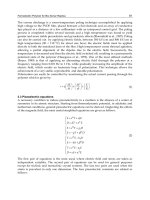
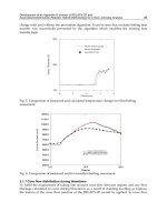
Ⅲ
One also considers that the attack of the environment and the cycles of
fatigue over the years do not lead to significant deterioration of the
composite pieces (shown in Figure 7.1 are two types of fatigue cycles for
the components of aircraft structure).
Ⅲ
The failure aspect subject to a moderate impact is more problematic with
the structures made of composite materials, because the energy absorbed
by plastic deformation does not exist.
Ⅲ
For the cabins, one uses phenolic resins. These have good fire resistance,
with low smoke emission. For the same reason, one prefers replacing
Kevlar fibers with a combination of glass/carbon (lighter than glass alone
and less expensive than carbon alone).
Ⅲ
It is possible to benefit from anisotropy of the laminates for the control
of dynamic and aeroelastic behavior of the wing structures.
7
7.1.5 Large Carriers
The following examples give an idea on the evolution of use of composites in
aircrafts over two decades:
Example:
Aerospatiale (FRA); Airbus Industry (EU) (Figure 7.2)
Example:
Boeing (USA) (Figure 7.3)
Figure 7.1 Temperature Cycle and Load Cycle for Components of an Aircraft
6
See Section 4.4.4.
7
See Section 7.1.8.
TX846_Frame_C07 Page 139 Monday, November 18, 2002 12:17 PM
© 2003 by CRC Press LLC
Ⅲ Notion of the exchange rate is the cost for a kilogram saved when one
substitutes a classical metallic piece with a piece made mainly with com-
posite. For the substitution light alloy—carbon/epoxy—this cost is on the
order of $160 (1984) per kilogram when the piece is calculated in terms
of rigidity (similar deformation for the same load). It is amortized over a
period of at least one year for the gain in “paying passenger.”
Ⅲ Notion of gain in paying passenger is the gain in terms of the number of
passengers, of freight, or in fuel cost; for example, for a large carrier:
Ⅲ An aircraft of 150 tons, with 250 passengers consists of 60 tons of
structure. A progressive introduction of 1600 kg of high performance
composite materials leads to a gain of 16 more passengers along with
their luggage.
Ⅲ A reduction of 1 kg mass leads to the reduction of fuel consumption
of around 120 liters per year.
Why are the reductions of mass (average about 20%) not more spectacular?
Consider the example of a vertical stabilizer. The distribution of mass of a composite
vertical stabilizer can be presented as follows:
Ⅲ Facings in carbon/epoxy: 30% of total mass
Ⅲ Honeycombs, adhesives: 35% of total mass
Ⅲ Attachments: 25% of total mass
Ⅲ Connections between carbon/epoxy components and attachments: over-
layers of carbon/epoxy
Ⅲ Allowance for the aging of the carbon/epoxy: overdimensions of the facings
(the stresses are magnified about 10% more for a subsonic aircraft and
13% for a supersonic aircraft)
In consequence, the global gain of mass in comparison with a classical metallic
construction for the vertical stabilizer is not more than an order of about 15%.
Example: European aircraft Airbus A-310–300 (Figure 7.5).
Figure 7.4 Cascading Effect in Mass Reduction
TX846_Frame_C07 Page 141 Monday, November 18, 2002 12:17 PM
© 2003 by CRC Press LLC
Example: European aircraft Airbus A-320 (Figure 7.6).
Ⅲ Total mass: 72 tons
Ⅲ Empty mass: 40 tons
Ⅲ Mass of structure: 21 tons
Ⅲ Mass of composite materials: 4.5 tons, corresponding to a reduction of
mass of the structure of 1.1 tons. The percent of composite mass is 21.5%
of the mass of the structure.
Ⅲ A few other characteristics: Length: 37.6 m; breadth: 34 m; 150 to 176
passengers transported from 3,500 to 5,500 km; maximum cruising speed:
868 km/h
Example: European aircraft Airbus A-340
Ⅲ Total mass: 253.5 tons
Ⅲ Mass of structure: 76 tons
Ⅲ Mass of composites: 11 tons, corresponding to a reduction of structure
mass of 3 tons
Ⅲ Percentage of composites: 14.5% of the mass of the structure
Example: Future supersonic aircraft ATSF (Figure 7.7), Aerospatiale (FRA) and
British Aerospace (UK). Principal characteristics defined at the stage before the
project
Ⅲ Transport of 200 passengers over a distance of 12,000 km
Ⅲ Cruising speed between Mach 2 (2,200 km/hr) and Mach 2.4 (2,600 km/hr)
Figure 7.6 Composite Components in an Airbus A-320
TX846_Frame_C07 Page 143 Monday, November 18, 2002 12:17 PM
© 2003 by CRC Press LLC