Composite Materials Handbook Part 5 pdf
Bạn đang xem bản rút gọn của tài liệu. Xem và tải ngay bản đầy đủ của tài liệu tại đây (70.81 KB, 15 trang )
MIL-HDBK-17-4
73
cern, therefore, is to get good quality specimens from these plates with no mistakes and minimal material
waste. Due to the inhomogeneity (that is, hard ceramic fibers and soft matrix) and the extreme anisotropy
of these materials, they are not easily machined. This is exacerbated by the fact that the plates are often
slightly warped due to the high residual stresses (due to the CTE mismatch between the fibers and the
matrix, as well as from irregular lay-ups, that is, fiber misalignment, non-uniform matrix layers) from
manufacturing of the plates. For these reasons, conventional machining practices do not work. Non-
conventional machining methods have been successfully used for these materials.
There are three ways in which these materials have typically been machined: wire electro-discharge
machining, abrasive water-jet machining, or diamond cutting/grinding of the entire specimen. All of these
methods have been used successfully for thinner materials (8-ply or less). For thicker materials, abrasive
water-jet cutting does not have a sufficient force to cut through the material and maintain accurate geome-
tries; therefore, one of the other machining methods must be used. The machining method chosen should
be maintained throughout the entire test program, if possible, to eliminate machining as a possible lurking
variable in the data.
When preparing 0° specimens, care must be taken to ensure that the fibers are aligned parallel to the
coupon axis. Likewise, when preparing specimens with off-axis or cross-ply fiber orientations, good
alignment should also be maintained between the coupon axis and the desired orientation. Large devia-
tions could result in errors in the mechanical properties. Typically, an alignment of ±1° is desired. Larger
deviations in alignment should be reported.
If damage on the edge of the gage section (this is a machined surface) is of concern either because it
is too rough to support an extensometer, too irregular to get an accurate measurement of the cross-
sectional area, or because there is a concern with machining damage influencing the test results, then the
specimens can be cut oversized by approximately 0.020 inches (0.050 cm) in the gage and radius sec-
tions and be subsequently diamond ground to final dimensions. Final grinding passes should be done in
the longitudinal direction (that is, the direction of loading) to avoid scratches that may initiate damage
(cracks).
Specimen edges (that is, machined surfaces) may be polished to aid in the viewing of cracks either by
optical or replicative means. The faces of the specimen, which consist of a layer of matrix material above
the outer most plies of fibers, are usually not prepared in any way. The reason for this is that the matrix
face layer is often thin, and there is a good chance that through the preparation process, fibers will be ex-
posed to the surface. This could damage the fibers, or at the least will provide an easy access for the en-
vironment into the material (note that the fiber coating on the SCS-6 fiber is an easy diffusion path for oxy-
gen). In either case, the mechanical properties could be compromised. However, polishing may be re-
quired to facilitate matrix-crack detection during fatigue and fatigue crack growth testing. If polishing of the
faces of the specimen is required, care should be taken to remove a minimum of matrix material. Light
polishing can be conducted with the following procedure: 320, 400, then 600 grit abrasive paper followed
by 6 and 3 micron diamond paste.
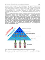
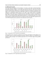
A sample of typical machining instructions is given in Figure 1.3.2.4(a) for the sample geometry given
in Figure 1.3.2.4(b). This sample design is used for uniaxial loading. Its design originated from a finite
element analysis, constructed to prevent failure in the transition area by minimizing and separating the
shear and axial stress concentrations which occur at the transition between the radius and the gage sec-
tion (Reference 1.3.2.4(a)). This geometry is proposed in the revision of ASTM Standard D3552-77 (the
latest version is ASTM D3552/D3552M-96), Test Method for Tensile Properties of Fiber-Reinforced Metal
Matrix Composites, as the recommended design for specimens of unidirectional composites. Other sam-
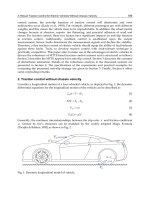
ple geometries may be used. Figure 1.3.2.4(c) shows a dogbone-shaped specimen which has been used
successfully and has the added advantage that it uses less material. The key to an adequate specimen
design is that the specimen must fail in the gage section. If failure frequently occurs in the transition, ra-
dius or grip areas, then the data from these specimens should be labeled as suspect and a new specimen
geometry sought.
MIL-HDBK-17-4
74
Rectangular cross-section gage
1)
Wire EDM material approximately 0.020" oversized on gage and radius cuts before grinding.
2)
Diamond grind on gage and radius to final dimensions as per detail dimensions shown.
3)
Remove final stock with a series of light passes to minimize the depth of damage and work
hardening.
4)
Material supplied is unique and not easily replaced; therefore, take extra care to set up correct
dimensions before making any cuts.
5)
The reduced gage section width (0.390") should be centered relative to the width (0.500") of the
specimen ends within + 0.001".
6)
The reduced gage section should be also centered with respect to the length (6”) of the speci-
men within ± 0.001”
7)
Cut surfaces marked A [gage edge and end edge] should be true and square. Also, A surfaces
should be parallel to specimen centerline within + 0.001".
8)
All radii must blend without undercuts or steps.
9)
Number each specimen with permanent ink and identify the unique position of the plate from
which it came.
10)
The one inch straight gage section and the radii must have a 32 rms finish or better.
11)
Thickness as supplied
12)
Return ALL material and scraps. Protect ground surfaces of specimen from damage.
FIGURE 1.3.2.4(a)
Machining instructions.
For specimens which contain off-axis plies, there is an additional factor in determining the gage
width/length of the specimen. A study has shown that when off-axis fibers in the gage begin, end, or begin
and end in either the radius or the grips, there is additional constraint on the specimen, thus affecting at
least the room temperature tensile properties (Reference 1.3.2.4(b)). Thus, while the gage width may
maintain a value identical to that of the unidirectional specimens, the gage width-to-length must be sized
such that there are few fibers from the gage ending in either the radius or grips. In other words, the fibers
in the gage section should begin and end in the straight gage section. Depending on the inclination of the
fibers with respect to the specimen axis, this may necessitate a longer gage section.
Specimens will often require a heat treatment to either age the
in-situ
matrix or to simulate some
thermomechanical treatment which the component may experience. The heat treatment should be per-
formed after machining for several reasons. First, the heat treatment may help relieve machining residual
stresses. Second, if only a few specimens are heat treated at a time and if there is a problem with the
heat treatment, then only a few specimens will be ruined and not the entire plate. Lastly, due to the high
residual stresses in the composite, the specimens may warp when cut out of the plate. This can be cured
by subsequent heat treating of the specimen under weight for creep flattening. It should be noted that due
to the high residual stresses in the composite, initially flat specimens may not come out of the heat treat
furnace as flat. In some cases, specimens have been observed to be so severely bent and warped that
they were rendered useless. Again, weighting the specimens during heat treatment should solve this
problem.
MIL-HDBK-17-4
75
FIGURE 1.3.2.4(b)
MMC/IMC dogbone specimen - 14.5” radius.
MIL-HDBK-17-4
76
FIGURE 1.3.2.4(c)
Flat dogbone specimen.
MIL-HDBK-17-4
55
1.3.2.5
Data documentation
Data Documentation Requirements Checklist
Material Name:
__________________________________
Data Submitted by:
__________________________________
Date Submitted:
___________________
Does Data meet MIL-HDBK-17 requirements for fully approved data?
____
Yes
____
No
For fully approved data, the requirements listed in Volume 4, Section 1.3.4 (Continuous Fiber Reinforced
MMC Constituent Material Properties) or Section 1.3.5 (Discontinuous Reinforced MMC & Constituent
Material Properties) must be fulfilled. In addition, all the items listed below marked by an arrow must be
provided either on the Submitter’s data tables or on this checklist in order to meet the handbook’s Full
Documentation Requirements. Otherwise, the data will be considered as Screening Data if those items
marked by an arrow are not supplied.
Name (POC):
___________________________
Organization:
___________________________
Telephone:
_____________________
MATERIAL IDENTIFICATION
†
➨
Reinforcement ID
†
➨
Matrix ID
†
➨
Continuous or Discontinuous
REINFORCEMENT INFORMATION
†
➨
Chemical Composition
†
➨
Form (fiber, whisker, particulate, and so on)
†
➨
Commercial Name
†
➨
Manufacturer
†
➨
Diameter
†
➨
Aspect Ratio (If Discontinuous)
†
Shape (If Discontinuous)
†
➨
Size Distribution (If Discontinuous)
†
➨ Lot Number(s)
➨ = For Full Documentation Requirements
MIL-HDBK-17-4
56
Material Name:
__________________________________
Data Submitted by:
__________________________________
Date Submitted:
___________________
REINFORCEMENT INFORMATION (Continued)
†
Reinforcement Nominal Density
†
➨
Nominal Filament Count (If Applicable)
†
➨
Fiber Alignment Material (crossweave)
†
➨
Fiber, Tow, or Yarn Count (per inch)
MATRIX INFORMATION
†
➨ Matrix Composition
†
➨ Matrix Supplier
†
➨ Matrix Heat No.
CONSOLIDATION PROCESS INFORMATION
†
➨
Manufacturer
†
Manufacture Date
†
➨
Process Sequence Description
†
➨
Process Temperature/Pressure/Time
COMPOSITE INFORMATION
†
➨
Product Form
†
➨
Material Lot/Serial/Part No.
†
Product Form Dimensions
†
➨
Reinforcement Volume Fraction
†
➨
Lay-Up & Ply Count (If Applicable)
†
➨
Nominal Density (g/cc)
†
➨ Void Content (If Cast Process)
➨ = For Full Documentation Requirements
MIL-HDBK-17-4
57
Material Name:
__________________________________
Data Submitted by:
__________________________________
Date Submitted:
___________________
SPECIMEN INFORMATION
†
➨
Machining Method
†
➨
Specimen Geometry
†
➨
Specimen Dimensions (including thickness)
†
➨
Surface Condition
†
➨
Specimen Orientations
†
➨
Pre-Test Exposure
†
➨
Tabbing Method (If Applicable)
MECHANICAL TESTING
†
➨
Type of Test(s)
†
➨
Test Method/Procedure
†
➨
Number of Specimens
†
Test Date
†
➨
Test Temperature
†
➨
Test Environment
†
➨
Failure Mode ID and Location
➨ = For Full Documentation Requirements
MIL-HDBK-17-4
58
Static Property Data Documentation
For static properties, the following quantities should be provided for each specimen in tabular (spread-
sheet) form as shown on the data table templates provided by MIL-HDBK-17 Secretariat:
† Specimen No. † F
ty0.2
(ksi)
† Fiber v/o † F
tu
(ksi)
† Lot I.D. (Plate No.) † ε
tu
(%)
† Test Temp. (°F ) † Test Date
† Strain rate (1/s) † Failure Location
† E
t
(Msi) † Failure Mode
† Proportional Limit (ksi) † Stress-Strain Data
† F
ty0.02
(ksi)
In addition, the supplier of data should include any other quantities they have readily available for each
specimen Add columns to the standard data table at the far right as needed. Examples of such quantities
are:
† Reduction of Area (%) † Ultimate Load (lbs)
† Elongation (%) † Gage Width (in)
† Area (in
2
) † Gage Thickness (in)
† Load @ 0.2% Offset (lbs) † Gage Length (in)
†
Poisson’s Ratio,
ν
1.3.3
MATERIALS PEDIGREE
When submitting data to the Handbook, a complete set of pedigree information is required. This is to
establish the validity of a manufacturer’s material system’s physical, chemical, and mechanical property
database. The requirements are necessary to establish justification for the inclusion of data into MIL-
HDBK-17. Documentation requirements ensure complete traceability and control of the database devel-
opment process from material production through procurement, fabrication, machining, heat treating,
gaging, and testing.
Data submitted must include a completed Data Documentation Checklist (see Section 1.3.2.5). Test
methods used must meet handbook recommendations at the time the tests were performed. All items in
this checklist are desired. Items marked with arrows are required for full approval. All information should
be traceable and available to the Secretariat. The Data Documentation Checklist is based on the informa-
tion necessary for composite level mechanical property testing. The information required for other tests or
material levels is similar.
MIL-HDBK-17-4
59
1.3.3.1
Reinforcement
1.3.3.2
Reinforcement sizing
1.3.3.3
Reinforcement coatings
1.3.3.4
Matrix
1.3.3.5
Intermediate forms characterization
1.3.3.5.1
Metallized fibers
1.3.3.5.2
Monotapes
1.3.3.5.3
Lamina other than monotapes
1.3.3.5.4
Specialized forms
1.3.3.6
Composite materials
1.3.4
CONTINUOUS FIBER REINFORCED MMC CONSTITUENT MATERIAL PROPERTIES
1.3.4.1
Screening
1.3.4.2
Acceptance testing of composite materials
This section recommends tests for the submission of fully approved data to the Handbook. The test
matrices are for data generation on composites, fiber, and matrix materials. The test matrices were de-
signed to allow a statistical analysis to be performed and to account for the anisotropic nature of these
materials. However, due to the high cost of these materials, the overall number of recommended tests
was kept at a minimum. All testing should follow the testing standards given in the Handbook.
MIL-HDBK-17-4
60
1.3.4.2.1
Composite static properties tests
TABLE 1.3.4.2.1
Composite static property tests.
Test Fiber
Directionality
Number of
Lots
Samples per
Lot
Number of Tests per
Condition
Tensile L 5 6 30
Tensile T 5 6 30
Compression L 5 6 30
Compression T 5 6 30
Shear (in-plane) L 5 6 30
Shear (in-plane) T 5 6 30
Pin-Bearing Tensile L 5 6 30
Pin-Bearing Tensile T 5 6 30
L is longitudinal and T is transverse.
1.3.4.2.2
Composite fatigue properties tests
TABLE 1.3.4.2.2
Composite fatigue tests.
Test Fiber
Directionality
Number of
Lots
Stress Levels Replicates Number of
Tests per
Condition
High-Cycle Fatigue L 3 5 2 30
High-Cycle Fatigue T 3 5 2 30
Low-Cycle Fatigue L 3 5 2 30
Low-Cycle Fatigue T 3 5 2 30
Fatigue Crack Growth Rate L 3 5 2 30
Fatigue Crack Growth Rate T 3 5 2 30
Creep/Stress Rupture L 3 5 2 30
Creep/Stress Rupture T 3 5 2 30
L is longitudinal and T is transverse.
MIL-HDBK-17-4
61
1.3.4.2.3
Composite thermal mechanical tests
TABLE 1.3.4.2.3
Composite thermal mechanical tests.
Test Fiber
Directionality
Number of
Lots
Stress
Levels
Replicates Number of
Tests per
condition
TMF in-phase (IP) L 2 3 2 12
TMF in-phase (IP) T 2 3 2 12
TMF out-of-phase (OP) L 2 3 2 12
TMF out-of-phase (OP) T 2 3 2 12
Tensile (after thermal cycling) L 5 - 6 30
Tensile (after thermal cycling) T 5 - 6 30
L is longitudinal and T is transverse.
1.3.4.2.4
Composite physical properties tests
TABLE 1.3.4.2.4
Composite physical properties tests.
Test Number of
Lots
Samples
per Lot
Number of Tests
per condition
Coefficient of Thermal Expansion (a) 5 1 15 min. per dir.
Specific Heat (b) 5 1 5
Thermal Conductivity (a) 5 1 15
Electrical Conductivity (a) 5 1 15
Density (c) 5 1 5
Volume Fraction (c) 5 1 15
(a)
Taken in the L (longitudinal), LT (long transverse), and WT (wide transverse)
directions
(b)
Property taken parallel to the fiber direction only
(c)
Property is independent of fiber orientation
MIL-HDBK-17-4
62
1.3.4.3
Intermediate forms characterization
1.3.4.3.1
Metallized fibers
1.3.4.3.2
Monotapes
1.3.4.3.3
Lamina other than monotapes
1.3.4.3.4
Specialized forms
1.3.4.4
Constituent characterization
1.3.4.4.1
Fiber properties tests
TABLE 1.3.4.4.1
Fiber property tests.
Test Number of
Lots
Samples per
Lot
Number of Tests
per condition
Tensile 5 30 150
Microstructure (with magnification) 5 3 15
Chemical Analysis 5 3 15
Axial Thermal Expansion 5 3 15
Diameter (range) 5 10 50
Density 5 1 5
Electrical Conductivity 1 1 1
Thermal Conductivity 1 1 1
MIL-HDBK-17-4
63
1.3.4.4.2
Matrix
TABLE 1.3.4.4.2
Matrix Property Tests.
Test Number of
Lots
Samples
per Lot
Number of Tests
per condition
Tensile 5 3 15
Fatigue 5 3 15
Creep 5 3 15
Crack Growth 5 3 15
Hardness 5 3 15
Microstructure (with magnification) 5 3 15
Chemical Analysis 5 3 15
Coefficient of Thermal Expansion 5 3 15
Density 5 1 5
Electrical Conductivity 1 1 1
Thermal Conductivity 1 1 1
MIL-HDBK-17-4
64
1.3.5
DISCONTINUOUS REINFORCED MMC & CONSTITUENT MATERIAL PROPERTIES
1.3.5.1
Composite materials characterization
1.3.5.1.1
Screening
1.3.5.1.2
Acceptance testing of composite materials
1.3.5.1.2.1
Composite static properties tests
1.3.5.1.2.2
Composite fatigue properties tests
1.3.5.1.2.3
Composite thermal mechanical tests
1.3.5.1.2.4
Composite physical properties tests
REFERENCES
1.3.2.4(a) Worthem, D.W., "Flat Tensile Specimen Design for Advanced Composites,” NASA CR-
185261, 1990.
1.3.2.4(b) Lerch, B.A. and Saltsman, J.F., "Tensile Deformation Damage in SiC Reinforced Ti-15V-3Cr-
3Al-3Sn, NASA TM-103620, 1991.
MIL-HDBK-17-4
65
1.4
COMPOSITE TESTING AND ANALYTICAL METHODS
1.4.1
INTRODUCTION
Section 1.4 contains test and analytical methods for characterizing metal matrix composites. The pur-
pose of this section is to provide standardized methods and commonly used techniques to pedigree the
material and to generate material property data. The test methods and techniques are representative of
procedures used in the composite materials industry. Existing standards are cited when they exist and are
applicable. When there are no such standards available, a test method has been proposed. The pro-
posed test methods are ones that are widely used within industry, academia, or government. Most of
these test methods are taken directly from usage on monolithic metals. However, since there are special
concerns regarding the testing of MMCs due to their brittle reinforcement phase and their highly aniso-
tropic nature, special consideration must be given when adapting such methods. Cautionary notes have
been added to many of the monolithic standards in order that they can be applied to MMCs.
1.4.2
CONTINUOUS FIBER REINFORCED MMC MECHANICAL PROPERTY TEST METHODS
1.4.2.1
Tension
General: Tensile testing of MMC laminates should be conducted in accordance with ASTM Test
Method D3552/D3552M Tensile Properties of Fiber Reinforced Metal Matrix Composites (Reference
1.4.2.1). The following additional points should also apply:
1.
A failure location within the area of one specimen width away from the grip or the specimen tab should
be considered as an "at grip" failure and these data should be "flagged" as such.
2.
When preparing [0] specimens, care must be taken to ensure that the fibers are aligned parallel to the
coupon axis. Likewise, when preparing specimens with off-axis or cross-ply fiber orientations, good
alignment should also be maintained between the coupon axis and the desired orientation. Large de-
viations could result in errors in the strength and modulus values. Typically, an alignment of ±0.5° is
desired. Larger deviations in alignment should be reported.
1.4.2.2
Compression
This test procedure covers the preferred manner to determine compressive mechanical properties of
MMCs. At the present, there are no standardized methods for such testing however, techniques devel-
oped for metals and polymer composites have been used with success. Various test fixtures have been
designed to introduce compressive loads to the test specimen while minimizing stress concentrations due
to gripping and misalignment. These fixtures include the Modified Celanese Fixture, The Illinois Institute of
Technology Research Institute (IITRI) Fixture, and the Sendeckyj-Rolfes Fixture. To date, the IITRI test
fixture is the most commonly used.
Compression tests on MMC's should be conducted in accordance with ASTM Standard D3410-87 (the
latest version is ASTM D3410/D3410M-95) "Standard Test Method for Compressive Properties of Unidi-
rectional or Crossply Fiber-Resin Composites" (Reference 1.4.2.2). The following additional points should
also apply:
1.
The IITRI compressive test fixture is the preferred test setup for continuous reinforcement metal
matrix composite.
2.
Strain gages should be affixed to the specimen using the manufacturer's recommended proce-
dures. Two strain gages (one on each face of the test specimen) should be used to determine the
magnitude of bending taking place during each test. The use of two gages will provide redun-
dancy and will help pinpoint problems that arise during testing. Strain readings that diverge from
the beginning of the test suggest specimen bending caused by test specimen/fixture misalign-