Dictionary of Material Science and High Energy Physics Part 7 pot
Bạn đang xem bản rút gọn của tài liệu. Xem và tải ngay bản đầy đủ của tài liệu tại đây (564.95 KB, 24 trang )
where A is the amplitude, α,β are constants,
t is the time, and x is the position. Hence,
as the amplitude increases the speed increases,
while the width shrinks. Solitons are related to
shock waves through a quasi-potential called the
Sagdeev potential.
ion acoustic wave The only normal mode
of ions allowed in nonmagnetized plasmas, ion
acoustic waves are essentially driven by ther-
mal motions of both electrons and ions. In fact,
their phase and group velocities are given by
the ion acoustic or sound speed c
s
={(KT
e
+
3KT
i
)/m
i
}
1/2
, where K is the Boltzman con-
stant, T
e
, and T
i
are the electron and ion tem-
peratures, and m
i
is the ion mass. With the use
of the ion acoustic speed, the dispersion relation
of the ion acoustic wave with frequency ω and
wave number k is given by ω=kc
s
. There
are two damping mechanisms for ion acoustic
waves; one is Landau damping and the other is
the non-linear Landau damping that occurs af-
ter trapping of particles inside the electrostatic
wave potential of relatively large ion acoustic
waves. Ion acoustic waves are heavily damped
ifT
e
<T
i
, so that such waves usually propagate
only in plasmas with T
i
T
e
. Various non-
linear states of ion acoustic waves have been the
subjects of intensive research in plasma physics
for many years. As they are amplified, these
waves may form solitons, double layers, and
shock waves. See also ion wave.
ion beam instabilities There are several in-
stabilities driven by an ion beam, which, in a
magnetized plasma, usually propagates along an
external magnetic field. Electrostatic instabili-
ties are the ion acoustic instability driven by the
relative drift between the electrons and the beam
ions and the ion–ion drift instability. The for-
mer generates principally field-aligned waves,
and the latter generates either field-aligned or
oblique waves. Among electromagnetic insta-
bilities are the ion–ion resonant and nonresonant
instabilities; the former excite right-hand circu-
larly polarized waves, and the latter excite left-
hand circularly polarized (Alfvén) waves at rela-
tivelylowdriftspeeds, i.e., thefire-hoseinstabil-
ity and right-hand circularly polarized waves at
higher speeds. Whistler waves can also be gen-
erated. Production of these right-hand circularly
polarized waves can be enhanced by increased
drift speed as well as increased perpendicular
temperature of the beam.
ion cyclotron resonance See cyclotron res-
onance.
ion cyclotron resonance heating (ICRH)
Hasbeenutilizedtoheatplasmasbyelectromag-
netic waves. For this scheme, an electromag-
netic ion cyclotron wave is launched from an
external source into a plasma with a frequency
ω, which is lower than the local ion cyclotron
frequency
i
of the target plasma. As the wave
propagates into a decreasing magnetic field, it
will eventually heat the target plasma efficiently
through cyclotron acceleration when the local
resonance condition ω=
i
is satisfied. This
heating scheme is frequently used in several fu-
sion devices such as tokamaks.
ion cyclotron wave When magnetized, plas-
mas can support electrostatic ion cyclotron
waves that propagate nearly perpendicular to
the external magnetic field. The dispersion re-
lation is given by ω
2
=
2
i
+k
2
c
2
s
, where ω
is the frequency, k is the wave number of the
wave,
i
is the ion cyclotron frequency, and c
2
s
is the ion acoustic speed. Experimentally, ion
cyclotron waves were first observed by Motley
and D’Angelo in a device called a Q-machine.
On the other hand, electromagnetic ion cy-
clotron waves propagate predominantly along
the magnetic field, and are left-hand polarized.
These waves are frequently used to heat ions in
plasma confinement devices, i.e., ion cyclotron
resonance heating (ICRH). See also ion wave.
ionic bonding The bonding in structures that
results from the net attraction between oppo-
sitely charged species. For example, in com-
pounds of the alkalis and a halogen atom (e.g.,
sodium chloride, NaCl), the chlorine atom de-
taches an electron from the sodium atom, form-
ing Na
+
and Cl
−
ions which together can form
a stable configuration or crystal structure. The
variation of the energy of the (Na
+
+Cl
−
) sys-
tem, E
s
(R), relative to the sum of the energies
of the isolated neutral atoms is given as
E
s
(R) = E
s
(∞) −
1
R
+ Ae
−hR
© 2001 by CRC Press LLC
flected light by 90
◦
with respect to the incident
light, and therefore the reflected light is blocked
by the polarizer. Rotation of the polarization is
generally achieved by using Faraday rotation in
magneto-optical material. Optical isolators are
very common in optical communications sys-
tems.
isomer (1) One of two or more nuclides that
have the sameatomicandmass numbers but dif-
fer in other properties.
(2) A nucleus which has the same proton and
neutron number as in other nucleus, but which
has a different state of excitation.
isomer (nuclear) An excited state of a nu-
cleus which has a measurable mean life. The
radioactive decay of such a state is said to occur
in an isomeric transition and the phenomenon is
known as nuclear isomerism.
isoscalar particle A particle with isospin
equal to zero.
isospin A property (or quantum number)
which distinguishes a proton from a neutron.
With respect to the nuclear force, a proton and
a neutron behave in essentially the same way.
In contrast protons and neutrons interact differ-
ently with a Coulomb field. With an isospin of
1
2
assigned to the nucleon, the two nucleons are
then distinguishable through the third compo-
nent of the isospin being +
1
2
for the proton and
−
1
2
for the neutron.
isothermalbulkmodulus(β
T
) Ameasureof
the resistance to volume change without defor-
mation or change in shape in a thermodynamic
system in a process at constant temperature. It
is the inverse of the isothermal compressibility.
β
T
=−V
∂P
∂V
T
.
isothermal compressibility (κ
T
) The frac-
tional decrease in volume with increase in pres-
surewhilethe temperatureremainsconstantdur-
ing the compression.
κ
T
=−
1
V
∂V
∂P
T
.
isothermal process A process at constant
temperature.
isotone One oftwoor morenuclidesthathave
the same number of neutrons in their nuclei but
differ in the number of protons.
isotope One oftwoor morenuclidesthathave
the same atomic number but different numbers
of neutrons so that they have different masses.
The mass is indicated by a left exponent on the
symbol of the element (i.e.,
1
4C).
isotope effect The correction to the energy
levels of a bound-state system due to the finite
mass of the nucleus.
isotope effect (superconductivity) Early in
the development of the theory of superconduc-
tivity, it was found that different isotopes of the
same superconducting metal have different crit-
ical temperatures, T
c
, such that
T
c
M
a
= constant
where M is the mass of the isotope and a ≈ 0.5
formostmetals. Thiseffectmadeit clearthatthe
lattice of ions in a metal is an active participant
in creating the superconducting state.
isotropic Independent of direction, or spher-
ically symmetric.
isotropic turbulence Implies that there is no
mean shear and that all mean values of quanti-
tiessuch asturbulenceintensity,auto- andcross-
correlations, spectra, and higher order correla-
tion functions of the flow variables are indepen-
dent of the translation or rotation of the axes of
reference. These conditions are not typical in
real flows. On the other hand, assumptions of
isotropic and homogeneous turbulence have led
to understanding of many aspects of turbulent
flows.
isotropy Having identical properties in all
directions.
isovector particle A particle with isospin
equal to one and, thus, three possible charge
states corresponding to the three possible val-
© 2001 by CRC Press LLC
ues (0, ±1) ofthe third componentof theisospin
vector.
ITER Originallyproposed at asummit meet-
ing between the USAand the USSR in 1985, the
purpose of the international thermonuclear ex-
perimental reactor [ITER] project is to build a
toroidal device called a tokamak for magnetic
confinement fusion to specifically demonstrate
thermonuclear ignition and study the physics of
burning plasma. The initial phase of this project
was jointly funded by four parties: Japan, the
European community, the Russian Federation
and the United States. In July of 1992, ITER
engineering design activities [ITER EDA] were
established to provide a fully integrated engi-
neering design as well as technical data for fu-
ture decisions on the construction of the ITER.
To meet the objectives, the linear dimensions of
ITER will be 2–3 times bigger than the largest
existing tokamaks. According to the 1998 de-
sign, the major parameters of the ITER are as
follows: total fusion power of 1.5G W, a plasma
inductive burn time of 1000 s, a plasma major
radius of 8.1 m, a plasma minor radius of 2.8 m,
a toroidal magnetic field at the plasma center of
5.7 T, and an auxiliary heating power by neutral
beam injection of 100 MW.
© 2001 by CRC Press LLC
J
Jacobicoordinates In describingthedynam-
ics of many-particle systems, we are often faced
with the task of choosing an appropriate set of
coordinates. Forexample,inthetwo-bodyprob-
lem, the motion relative to the center of mass is
described by the one-body Schrödinger equa-
tion:
i
¯
h
∂(r,t)
∂t
=
−
¯
h
2
2µ
∇
2
r
+ V(r)
(r,t)
µ =
m
1
m
2
m
1
+m
2
is the reduced mass for particles
of mass m
1
and m
2
, and r = r
1
− r
2
are the
relative position vectors of particles 1 and 2.
Suitable sets of center-of-mass coordinates can
be similarly constructed for systems containing
any number of particles. For example, consider
the three-body problem
A set of Jacobi coordinates for a three-body system.
We first consider particles 1 and 2 as a sub-
system with relative coordinate r and center of
mass µ. The motion of the center-of-mass of
this sub-system relative to the third particle is
described through the second position vector ρ.
The Schrödinger equation for this system then
reads:
i
¯
h
∂(r,ρ,t)
∂t
=
−
¯
h
2
2µ
∇
2
r
+
−
¯
h
2
2µ
∇
2
ρ
+ V(r,ρ)
(r,ρ,t)
where µ
=
(
m
1
m
2
)
m
3
m
1
+m
2
+m
3
, with m
3
representing
the mass of particle 3. Coordinate systems of
this kind where the kinetic energy is separable
are called Jacobi coordinates.
Jahn Teller effect (rule) A non-linear mol-
ecule in a symmetric configuration with an or-
bitally degenerate ground state is unstable. The
molecule will seek a less symmetric configu-
ration with an orbitally nondegenerate ground
state. Although this rule was introduced to de-
scribe molecules, it has applications to impuri-
ties and defects in solids. An impurity ion can
move from a symmetric position in a crystal to a
position of lower symmetry to lower its energy.
A free hole in an alkali halide crystal (such as
KCI) can be trapped by a halogen ion and be-
comes immobile; it moves only by hopping to
another site if thermally activated.
Jansky, K. Astronomers have always
searched for ways of studying celestial objects
like comets, stars, and galaxies. One of the
most widely used methods of studying objects
in the sky is through the electromagnetic radi-
ation reaching us from these objects. Because
of the absorption of electromagnetic radiation
propagating from outer space to us, we can only
use limited bands (ranges of frequencies). One
band was discovered in 1931 by K. Jansky. He
discovered radio waves coming from the Milky
Way. This discovery was very ground-breaking
as it opened up a new field called radioastron-
omy, through which new discoveries about the
universe such aspulsars, quasars and the univer-
sal radiation at3Khavebeen made.
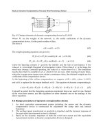
Jaynes–Cummingsmodel (1) Describesdy-
namics of a two-level atom interacting with a
single mode of radiation field in a lossless cav-
ity. This model is perhaps the simplest solvable
model that describes the fundamental physics
of radiation–matter interaction. This somewhat
idealized model has been realized in the labo-
ratory by using Rydberg atoms interacting with
the radiation field in a high-Q microwave cav-
ity. The Hamiltonian for the Jaynes–Cummings
model in the rotating-wave approximation is
© 2001 by CRC Press LLC
given by
ˆ
H =
1
2
¯
hω
0
ˆσ
3
+
¯
hω
ˆa
†
ˆa +1/2
+
¯
hλ
ˆσ
+
ˆa +ˆa
†
ˆσ
−
.
Here, the Pauli matrices ˆσ
+
, ˆσ
−
, and ˆσ
3
repre-
sent the raising, lowering, and inversion opera-
tors for the atom, ω
0
is the transition frequency
for the atom, and ω is the field frequency. Oper-
ators ˆa
†
and ˆa are the creation and annihilation
operators of the field-satisfying boson commu-
tation relations.
(2) The simplest model in cavity quantum
electrodynamics. IntheJaynes-Cummingsmod-
el, one assumesthat a two-level atomwith upper
level |a and lower level |b interacts with only
onemodeof thequantizedelectromagneticfield.
Furthermore, this mode is assumed to be reso-
nant with the atomic transition frequency. The
Hamilton operator in the rotating wave approx-
imation for this problem is given by
H =ω
0
b
†
b +
1
2
¯
hω
0
σ
z
+
¯
hg
bσ
+
+ b
†
σ
−
.
Here g is the coupling constant, ω
0
is the reso-
nant transition frequency of the atoms, and σ
+
,
σ
−
, and σ
z
are the well-known Pauli spin matri-
ces. This reflectsthe possibilityof interpreting a
two-level system as a spin 1/2 system with spin
up when the population is in the upper state and
spin down for a population of the lower state.
The first two terms of the Hamiltonian de-
scribing the energy eigenstates of the photons
and the two-level atom commute with the sec-
ond part describing the interaction of the sys-
tem. This results in the possibility of writing
the eigenstates for the Hamiltonian as a combi-
nation of the eigenstates of the atom and field.
The eigenstates and eigenvalues for such a
system are given by
|
+
=
1
2
|n, a+|n + 1,b
|
−
=
1
2
|n, a−|n + 1,b
where n is the number of photons in the field.
The eigenvaluesfor thesestates are ±
¯
h, where
2
=
2
+ 4g
2
(n + 1)
is called the Rabi frequency. A possible detun-
ing of the quantized cavity field with the atomic
resonance isalso taken intoaccount here. As-
suming that the atom is initially in the excited
state and the field has n photons, one can cal-
culate the probability of finding the atom in the
excited state and the atom in a state with n pho-
tons at time t to
P
n,a
(t) = cos
2
(t) .
One sees oscillatory behavior in time, which is
called the Rabi oscillations or Rabi mutations.
In case the radiation field is in a coherent super-
position, quantum effects like recurrence phe-
nomena can be observed.
Of greatest interest is the strong coupling
limit where the coupling g is stronger than the
dissipation processes of the cavity and the spon-
taneous decays of the atomic levels.
The Jaynes-Cummings model is the basis for
the micromaser experiments, where a single at-
ominteracts witha high-Qcavity. Thetwo-level
characteristics of the atom are approximated by
excitingthe atom intoa Rydbergstate before en-
tering thecavity. The interactiontime canbe de-
termined by using velocity selective excitation
into the Rydberg states. Pure quantum phenom-
ena such as quantum collapse and revival can be
observed.
Jeans instability A plasma under the influ-
ence of a gravitational force is unstable due to
the Jeans instability, for which waves longer
than the Jeans length grow exponentially. This
phenomenon is analogous to ordinary plas-
ma waves propagating without being Landau-
damped, providedthattheirwavelengthsaresuf-
ficiently long.
Jeans, Sir J. Sir J. Jeans, together with Lord
Rayleigh, derived a spectral distribution func-
tion todescribe black-body radiation. Theirthe-
ory was called the Rayleigh–Jeans theory and
could only explain the long-wavelength behav-
ior of the spectrum. They derived a spectral
function ρ
(
λ, T
)
, where λ is wavelength and
T is temperature, for the radiation emitted from
an enclosed cavity (black-body) using the laws
of classical physics. They modeled the thermal
waves in the cavity as standing waves (modes)
of wavelength λ. They calculated the number
© 2001 by CRC Press LLC
of modes per unit of volume in the wavelength
rangeλ → λ+dλ, n(λ), as
8π
λ
4
dλ. Thiswasthen
multiplied by the average energy in the mode,
ε,
to give the spectral density
ρ
(
λ, T
)
=
8π
λ
4
ε.
Rayleigh and Jeans surmised that the stand-
ing waves arecaused by constantabsorption and
emission of radiation of frequency ν by classi-
cal linear harmonic oscillators in the walls of
the cavity. They assumed that the energy of
each oscillator can take any value from 0 to ∞,
which turned out to be an erroneous assump-
tion. The average energy of a collection of such
oscillators was calculated, using classical sta-
tistical mechanics, to be k
B
T , where k
B
is the
Boltzmann constant. Thus, they predicted the
black-body distribution to be
ρ
(
λ, T
)
=
8π
λ
4
k
B
T.
Thisisthe Rayleigh–Jeanslaw. Itagreesonly
in the long-wavelength limit and diverges for
λ → 0.
jellium A model in which the positive
charges of the ions in a metal are uniformly
spread (like jelly) in the volume occupied by the
ions. It is the closest realization of the Thomson
atom.
jellium model Used in the study of the cor-
relation effects in an electron gas. The basic
premise is that the atoms in the lattice are re-
placed with a uniform background of positive
charge.
jet Efflux of fluid from an orifice, either two-
or three-dimensional. In the former case, the
jet is emitted from a slit in a wall. In the latter
case, the jet exits through a hole of finite size.
Jets expand by spreading and combining with
surrounding fluid through entrainment. A jet
may either be laminar or turbulent.
JET The Joint European Torus (JET) lo-
cated at Abingdon in Oxfordshire, England is a
toroidal tokamak-type device for magnetic con-
finement fusionjointly operatedby 15 European
nations. The JET project was set up in 1978,
and thereareapproximately 350scientists, engi-
neers, and administrators supported by a similar
number of contractors. Even though the project
was officially terminated in 1999, the JET fa-
cilities have still been in operation since then.
This device, being the largest of its kind in the
world as well as the first to achieve the break
even condition (input power = output power), is
of approximately 15 meters in diameter and 12
meters high. The central portion of the device
is a toroidal vacuum vessel of major radius 2.96
meters with a D-shaped cross-section of 2.5 me-
ters by 4.2 meters; the toroidal magnetic field at
the plasma center is 3.45T, and the plasma cur-
rents are 3.2–4.8 MA. It also has an additional
heating power of over 25MW. It is presently the
only device in the world which is capable of
handling as its fuel the deuterium–tritium [DT]
mixtures used in a future fusion power station.
jet instability From linear stability theory,
jets are unstable above a Reynolds number of
four, similar to Kelvin–Helmholtz instability.
The resulting jet motion consists of vortical
structures which roll up with surrounding fluid
and dissipate downstream.
jet pump Similar in design to an aspirator,
except both working fluids are usually of the
same phase.
jets in nuclear reactions Back-to-back
streams of hadrons produced in nuclear reac-
tions. Jets are usually observed when quarks
and antiquarks (free for just a very short time)
fly apart. This can be observed, for example,
through the reaction e
+
+e
−
→ γ → q +¯q →
hadrons. When the quarks reach a separation
of about 10
−15
m, their mutual strong inter-
action is so intense that new quark-antiquark
pairsare producedand combineinto mesonsand
baryons, which emerge in two (and sometimes
three) back-to-back jets.
j–j coupling A possible coupling scheme for
spins and angularmomenta of the individual nu-
cleons in a nucleus. In the j −−j scheme, (as
opposed to the LS scheme), first the intrinsic
spin and orbital angular momentum of each nu-
cleon are added together to yield the total an-
gular momentum of a single nucleon. Then the
© 2001 by CRC Press LLC
angular momenta of the individual nucleons are
summed up to give the total angular momentum
of the nucleus.
j-meson/resonance Also known as the
meson. Particle discovered in 1974, which con-
firmed the existence of the fourth quark (the
charm quark).
Johnson noise Noise in an electric circuit
arising due to thermal energy of the charge car-
rier. Noise power P generated in the circuit due
to the Johnson noise depends on the tempera-
ture T and frequency band ν considered, but
is independent of the circuit elements.
P =
hνν
exp[−hν/ kT ]−1
,
where k is the Boltzmann constant. For kT >>
hν, the noise power can be approximated to be
kT ν. This noise can be reduced by cooling
the components generating the noise. It is also
called Nyquist noise.
Jones calculus Introduced by R. Clark Jones
to describe the evolution of a polarization state
when it passesthrough variousoptical elements.
In theJones matrix formulation,the polarization
of a plane wave is represented by a pair of com-
plex electric field components E
1
and E
2
, along
twomutuallyorthogonal directionstransverseto
the directionofpropagation, written asa column
matrix with (0 ≤ β ≤ π/2):
1
E
2
1
+ E
2
2
E
1
e
iδ
E
2
=
cos β
e
iδ
sin β
,
β = tan
−1
E
2
E
1
.
The actionof variouspolarizing elementsis then
described by complex 2 ×2 matrices which act
on the column matrix representing the polariza-
tion state. For example, the Jones matrix for a
quarter wave plate whose fast axis is horizontal
is given by
M = e
iπ/4
10
0 i
.
These matrices are derived in paraxial approxi-
mations.
Jones matrix 2×2 matrix which describes
the effect of an optical element on the polariza-
tion of light. The polarization of the light can
be described with a two-dimensional Jones vec-
tor. Horizontal and vertical polarization can be
described as two vectors
1
0
(horizontal) and
0
1
(vertical) .
An ideal polarizer (without loss) at an angle θ
with respect to the horizontal has the Jones ma-
trix,
cos
2
θ sin θ cos θ
sin θ cos θ sin
2
θ
.
For a linear retarder, which introduces a phase-
shift of δ to one polarization direction and is
aligned so that the optic axis makes an angle θ
with respect to the horizontal, we find a Jones
matrix given by
cos
2
θ +sin
2
θ exp(−ıδ) cosθ sinθ(1 − exp(−ıδ))
cos θ sin θ(1 −exp(−ıδ)) sin
2
θ +cos
2
θ exp(−ıδ)
.
The special cases for aλ/2-plate and a λ/4 plate
are easily calculated using δ = π and δ = π/2
respectively.
Jones vector Used to represent the polariza-
tion of an electromagnetic wave. It can also be
used torepresent any vectorin atwo-dimension-
al space. These vectors can be expressed as a
superposition of two basis vectors. The coeffi-
cients for the two vectors can be written as the
components of a two-dimensional vector, which
is called a Jones vector. Vertical and horizontal
polarization can then be represented as
1
0
(horizontal) and
0
1
(vertical) .
Any operation on this vector can then be ex-
pressed as a 2 × 2 matrix, which is the Jones
matrix.
An alternative basis for describing the polar-
ization properties is via left and right circular
polarized light. These can be written as
1
√
2
1
−i
(lefthand circular) and
1
√
2
1
i
(righthand circular) .
© 2001 by CRC Press LLC
Jones zones Volumes in k space (reciprocal
lattice) bounded by planes which are perpendic-
ular bisectors of reciprocal lattice vectors (as in
the case of the Brillouin zones). These planes
correspond to strong Bragg reflection for x-rays.
Strong x-ray scattering suggests strong Bragg
reflection for electron waves and the presence of
large Fourier coefficientsV(G) for the potential
which the electron sees, where G
is the recipro-
cal lattice vector involved. This means that if the
Jones zone is nearly filled with electrons, those
electrons near the zone boundary within an en-
ergy interval of approximately 1/2|V(G)| will
lower their energy by approximately |V(G
)|,
or |V| for short, each below the free elec-
tron energy. The net energy reduction for the
electron gas is approximately 1/2N(E
f
)|V|
2
,
where N(E
f
) is the electron density of states at
the Fermi energy E
f
which gives a binding en-
ergy of 3/4|V|
2
/E
f
per electron. This method
can be applied even to a covalent crystal such
as diamond, silicon, or germanium. Direct lat-
tice is a face-centered cubic with cube side a,
and has two atoms per unit cell separated by
the vector τ=(1, 1, 1)a/4. The Fourier coeffi-
cientV(G
) of the crystal is that of a monoatomic
crystal V
0
(G
) multiplied by the structure factor
(1 + exp(−iG
•τ), which we call S(G). Since
reciprocal space is a body-centered cubic lattice
with side (2/a)2π, we see that the eight recip-
rocal lattice vectors (2π/a)(±1,±1,±1) give
|S|
2
= 2 and will define a Jones zone which can
accommodate(9/8)N states for each spin direc-
tion (and not N as we always have for Brillouin
zones). Here,N is the number of unit cells (Bra-
vais) of direct lattice. A larger Jones zone can
be constructed fromthe twelve reciprocal lattice
vectors of the type 4π/a(±1, ±1, 0), which can
accommodate all the valence electrons of the
crystal (8N). Such ideas might explain the sta-
bility of certain metals and alloys. See nearly
free electrons.
Jönsson, C. The wave behavior of electrons
was demonstrated in 1961 by C. Jönsson in an
electron diffraction experiment.
Jordan, P. Two equivalent formulations of
quantum mechanics were put forward at about
the same time between 1924–1926. The first
formulation, called wave mechanics, was devel-
Jönsson used 40 keV electrons. The slits were made
in a copper foil and were very small
∼ 0.5 microns
wide and the slit separation
∼2 microns. Interference
fringes were observed on a screen at a distance of 0.4
m from the slits. Since the fringe separation was very
small, an electrostatic lens was used to magnify the
fringes.
oped by E. Schrödinger. The other is matrix
mechanics, which was developed by W. Heisen-
berg, M. Born, and P. Jordan.
Josephson, B.D. In 1962, B.D. Josephson
published a paper predicting two fascinating ef-
fects of superconducting tunnel junctions. The
first effect was that a tunnel junction should be
able to sustain a zero-voltage superconducting
dc current. The second effect was that if the
current exceeds its critical value, the junction
begins to generate high-frequency electromag-
netic waves.
Josephson effect (1) (i) DC effect: In a
Josephson junction, an insulating oxide layer is
sandwiched between two superconductors.
In each superconductor, electrons condense
into Cooper pairs, which tunnel through the in-
sulating layer. We define a wave function, also
calledanorderparameter, foreachsuperconduc-
tor. In superconductor 1, the order parameter is
written as
1
(x, t) = n
1
2
s
e
−iφ
1
φ
1
= φ
s1
+ ωt
where φ
s1
is the phase of the time-independent
part of the order parameter. Similarly, for su-
© 2001 by CRC Press LLC
Josephson junction made from two superconductors
separated by a thin oxide layer.
perconductor 2,
2
(x, t) = n
1
2
s
e
−iφ
2
φ
2
= φ
s2
+ ωt
n
s
is the number density of Cooper pairs in the
leftandrightsuperconductors, whichisassumed
to be the same. Using the familiar expressions
for current in terms of the wave functions
1,2
that are used in studying tunnelling in potential
barriers, we obtain the current J as
J = J
0
sin θ
where θ = φ
1
− φ
2
. Thus a DC current flows
across the barrier if there is a phase gradient.
(ii) ACeffect: Ifa voltage V isapplied across
the junction, there is a change in the energy of
the Cooper pairs, resulting in a change in the
phase of the time-dependent part of the order
parameter. We obtain
φ
1
= φ
s1
+
ω +
eV
¯
h
t
and
φ
2
= φ
s2
+
ω −
eV
¯
h
t.
Thus, we have applied a potential of
V
2
to
superconductor 1 and
−V
2
to superconductor 2.
The current in this case is time-dependent, since
θ = φ
1
− φ
2
=
(
φ
s1
− φ
s2
)
+
2eV
¯
h
t. Due to
the nature of the current this case is called the
Josephson AC effect.
(2) A Josephson junction can be made of two
good superconductors separated by a thin layer
of 10 Å of an insulator, and a normal (nonsuper-
conducting metal) or weaker superconductor. A
current of Cooper pairs (bound electron pairs)
wouldflow acrossthe junctionevenif there isno
potential difference (voltage) between the two
good superconductors. If a DC voltage V
0
is
applied, an oscillating pair current of angular
frequency |qV
0
/h|results where q is the charge
on the Cooper pair (twice e, the electron charge)
and h is Planck’s constant divided by 2π. If, in
addition to V
0
, we add an oscillatory voltage
v sin ωt, we find that the pair current J is given
by
J ≈ sin
[
δ
0
+
(
qV
0
t/h
)
+ (qv/hω) sin ωt
]
,
where δ
0
is a constant. This formula predicts
that when ω = (qV
0
/hn), where n is an integer,
there will be a DC current component present.
Two or more Josephson junctions can be con-
nected in parallel in a magnetic field, and their
current displays interference effects similar to
those of diffraction slits in optics.
Josephson radiation If a DC current greater
than the critical current flows through a Joseph-
son junction, it causes a voltage V(t) to appear
Variation of the voltage V(t) across a Josephson junc-
tion versus
ωt.
across the junction which oscillates with time.
This causes the emission of electromagnetic ra-
diation of frequency ω, such that the average
© 2001 by CRC Press LLC
voltage across the junction, V, is given as
2e
V =
¯
hω.
The first experimental observation of Joseph-
son radiation was reported in 1964 by I.K. Yan-
son, V.M. Svistunov, and I.M. Dmitrenko. The
English translation of this paper appears in Sov.
Phys. JETP, 21, 650, 1965.
Josephson vortices Consider the following
Josephson junction in a magnetic field H
0
:
Josephson junction in a magnetic field H
0
.
If the junction is placed in a magnetic field
H
0
directed along the z-axis, a screening super-
current is generated at the outer surfaces of each
slab. Such current is constrained to flow within a
thin layer. The magnetic field at x can be shown
to be proportional to
dφ
dx
, where φ is the phase
difference between the superconductors. The
differentialequationwhichdescribesφ (Ferrell–
Prange equation) is
d
2
φ
dx
2
=
1
λ
2
J
sinφ
whereλ
J
is the Josephson penetration depth and
gives a measure of penetration of the magnetic
field into the junction. In a weak magnetic field,
the above equations give solutions for the phase
difference φ and magnetic field H as
φ(x)=φ(0) exp
(
−x/λ
J
)
H(x)= H
0
exp
(
−x/λ
J
)
.
If the external field increases beyond a cer-
tain critical value which is characteristic of the
junction, the magnetic field penetrates into the
junction in the form of a soliton or vortex. This
is called a Josephson vortex.
Joukowski airfoil See Zhukhovski airfoil.
joule Unit of energy in the standard interna-
tional system of units.
Joule effect (Joule magnetostriction) Change
in the length of a ferromagnetic rod in the di-
rection of the magnetic field when magnetized.
See magnetostriction.
Joule heating The electrical energy dissi-
pated per second as heat in a resistor of resis-
tance R ohms and carrying a current of I am-
peres is equal to I
2
R watts.
Joule–Thompson effect A process in which
a gas at high pressure moves through a porous
plug into a region of lower pressure in a ther-
mally insulated container. The process con-
serves enthalpy and leads to a change in tem-
perature.
j-symbols Symbolsusedinthecontextofan-
gular momentum algebra in quantum mechan-
ics. For example, the symbol <j
1
j
2
m
1
m
2
|JM
> indicates the coupling of the two angular mo-
menta j
1
and j
2
to a total angular momentum
J . In this framework, m
1
, m
2
, and M are the
magnetic quantum numbers associated with the
component of their respective angular momenta
along a pre-chosen direction.
JT-60 InSeptember1996, thebreakevenplas-
ma condition (input power =output power) was
first achieved by JT-60, which proved the fea-
sibility of a fusion reactor based on the toka-
mak scheme. Located in Naka, Japan, and op-
erated by Japan Atomic Energy Research Insti-
tute[JAERI], JT-60, a toroidal device for mag-
netic confinement fusion, is one of the largest
tokamak machines in the world. JT-60U, the
upgraded version of JT-60 had a negative-ion
based neutral beam injector installed in 1996,
and the divertor transformed from open into W-
shaped semi-closed in 1997. The major param-
eters of JT-60 are as follows: a plasma major
radius of 3.3 m, a plasma minor of radius 0.8 m,
a plasma current of 4.5M A, a toroidal magnetic
© 2001 by CRC Press LLC
field at the plasma center of 4.4 T, and an auxil-
iary heating power by neutral beam injection of
30 MW.
JT-60U at JAERI.
jump conditions Variation in Mach number
and other flow variables across a shock wave.
For a normal shock wave, a variation in Mach
number across a shock is only a function of the
upstream Mach number as
M
2
2
=
(γ −1)M
2
1
+ 2
2γM
2
1
− (γ −1)
where γ is the ratio of specific heats. For M
1
=
1,M
2
= 2; this is the weak wave limit where
the wave is a sound wave. For M
1
∞,M
2
=
√
(γ −1)/2γ ; this is the infinite limit which
shows that there is a lower limit which the sub-
sonic flow can attain. For air, γ = 1.4; this
becomes M
2
= 0.378. Thus, the Mach num-
ber (but not the velocity) can go no lower than
this limit. The jump in density and velocity is
related by the continuity equation
ρ
2
ρ
1
=
u
1
u
2
=
(γ +1)M
2
1
(γ +1)M
2
1
+ 2
while momentum yields the jump in pressure
p
2
p
1
= 1 +
2γ
γ +1
M
2
1
− 1
.
These can be combined with the ideal gas equa-
tion to obtain
T
2
T
1
=
a
2
2
a
2
1
=
2γM
2
1
− (γ −1)
(γ −1)M
2
1
+ 2
(γ +1)
2
M
2
1
.
Since the flow is adiabatic, the stagnation or to-
tal temperature across a shock wave is constant.
Thus,
T
02
T
01
= 1 .
The above relations show that pressure, den-
sity, and temperature (hence, speed of sound)
all increase across a shock wave, while the Mach
number and total pressure decrease across a
shock.
junction (i) p–n: Formed when a semicon-
ductor doped with impurities (acceptors) is de-
posited on another semiconductor doped with
impurities (donors). It should be noted that a
semiconductor doped with donors is called an
n-type semiconductor, and those doped with ac-
ceptors are called p-type semiconductors. A
semiconductor doped with acceptors possesses
holes in its valence band. For example, sup-
pose a small percentage of atoms in pure sil-
icon are replaced by acceptors like gallium or
aluminium. Gallium and aluminium each have
three valence electrons occupying energy levels
just above the valence band of pure silicon (∼
0.06 eV). It is energetically favorable for an elec-
tron from a neighboring silicon atom to become
trapped at the acceptor atom, forming an Al
−
or
Ga
−
ion. This electron originates from the va-
lence band and leaves a vacancy or hole in this
band. Such holes can carry a current which dom-
inates the intrinsic current of the host. Donor
impurities in silicon have five valence electrons.
Each of the electrons can form a covalent bond
with one of the four valence electrons in a silicon
atom. This leaves an extra unpaired electron that
is loosely bound to the donor atom. The energy
levels of this extra electron lie close to the con-
duction band of silicon (∼ 0.05 eV below) and
can thus be excited to the conduction band and
added to the number of charge carriers. Some
uses of the p–n junction are in making solar cells,
rectifiers, and light-emitting diodes.
(ii) p–n–p: Type of junction is often used
as an amplifier in transistors. It consists of an
n-type semiconductor sandwiched between two
p-type semiconductors. Small changes in the
applied voltage cause changes in the emitter cur-
rent. For V
in
V
E
, the change in the collector
© 2001 by CRC Press LLC
current is given by
I
C
= ηI
E
whereη isameasureofthefractionoftheemitter
current reaching the collector, and I
E
is the
change in the emitter current due to a change in
V
in
(V
in
). The resulting amplification is then
given by
V
out
V
in
and can be in excess of 100.
p-n-p junction as an amplifier.
© 2001 by CRC Press LLC
K
Kadomtsev instability One of the screw (or
current convective) instabilities that occurs
when an electric current flows through a magne-
tized fully ionized plasma having screw-shaped
density perturbations. As a result of the in-
stability, spiral clouds of protons (or ions) and
electrons are generated and move along the field
linesin theopposite directions,creating acharge
separation and, thus, an electrostatic instability.
Kadomtsev–Nedospasov instability One of
the screw (or current convective) instabilities
that occurs when an electric current flows
through a magnetized partially ionized plasma
having screw-shaped density perturbations.
Therefore, this is also called the screw instabil-
ity in a partially ionized plasma. This instability
is triggered when theparallel drift speed of elec-
trons exceeds a threshold velocity that depends,
among other factors, on the collision frequency
between electrons and neutrals.
kaon A meson with a rest mass equal to ap-
proximately 494 MeV/c
2
. The kaon has a life-
time of 1.24 × 10
−8
s and decays (mostly) into
muons and neutrinos. The kaon is a strange par-
ticle, namely it has the strange quark among its
constituents.
Kármán constant From the law of the wall,
the constant k in the equation describing the
overlap layer
f
y
+
=
1
k
ln
y
+
+A
where y
+
≡ yu/ν and u
∗
≡
√
t
o
ρ. A varies
depending on the geometry. Observations show
that k ≈ 0.41.
Kármán momentum integral Approximate
solution for an arbitrary boundary layer for both
laminar and turbulent flows. Theequation is de-
rived from the momentum equation and is given
by
d
dx
U
2
θ
+ δ
∗
U
dU
dx
=
τ
o
ρ
where θ is the momentum thickness and δ
∗
is
the displacement thickness.
Kármán–Tsien rule Compressibility cor-
rection for pressure distribution on a surface at
a high subsonic Mach number in terms of the
incompressible pressure coefficient, C
p
o
:
C
p
=
C
p
o
1 − M
2
∞
+
M
2
∞
1+
√
1−M
2
∞
C
p
o
2
.
Kármán vortex street Periodic vortex wake
behind a circular cylinder at moderate Reynolds
numbers, 80 < Re < 200. The wake is charac-
terized by regular vortical structures shed from
opposite sides of the cylinder at a Strouhal num-
ber of 0.2. The motion becomes chaotic, but the
street is still prevalent until a Reynolds number
of approximately 5000.
kayser (1k) A traditional spectroscopic unit.
Today the inverse centimeter (cm
−1
) has re-
placed the kayser as the unit for the wave num-
ber: 1 cm
−1
=1k.
K-capture Process in which the nucleus of
an atom captures one of the atomic K-electrons
(electrons of the innermost shell) and emits a
neutrino. The general electron capture reaction
can be written as
A
Z
X +e
−
→
A
Z−1
X +ν
e
where X is a nucleus with Z protons and A nu-
cleons, and ν
e
is an electron neutrino.
Kelvin–Helmholtz instability Instability
formed at the interface between two parallel
flows ofdifferent velocities. Theshear resulting
from the discontinuous velocity rolls up into a
periodic row of vortices.
Kelvin scale of temperature (K) Defined
by choosing the unit of temperature so that the
triple point of water, the temperature at which
water, ice, and water vapor coexist, is exactly
273.16 K.
© 2001 by CRC Press LLC
Kelvin’s circulation theorem The circu-
lation around a closed loop in an inviscid
barotropicflowremainsconstant overtime, such
that
D
Dt
= 0
which means that circulation does not decay.
For flows with viscosity, circulation decays due
to viscous dissipation such that
D
Dt
< 0 .
Kelvin wedge Envelope of surface wave dis-
turbances emitted at successive times from a
moving point on the surface of water. In deep
water, the wedge has a half-angle of 19.5
◦
.
Kennard packet In quantum mechanics a
particle is described by a wave function so that
its position and momentum cannot be specified
simultaneously. A Kennard packet is the wave
packet describing the particle state that resem-
bles a classical particle state as closely as possi-
ble. The root-mean-square deviations (x and
p ) of position and momentum from their re-
spectivemean valuesarechosen tobe assmallas
possible. Their product is assumed to be equal
to one half of Planck’s constant divided by 2π.
Kerr effect Birefringence caused in an opti-
cally isotropic material by a transverse electric
field. The amount of birefringence induced by
the electric field of strength E is proportional to
the square of the electric field:
|
n
o
− n
e
|
∝ E
2
,
where n
o
and n
e
are the ordinary and extraordi-
nary indices of refraction respectively.
Some materials can exhibit an intensity-de-
pendent index of refraction of the form
n = n
0
+ n
2
E
2
= n
0
+ n
2
I.
These Kerr media have a potential use in quan-
tum non-demolition measurements. As depic-
ted in the figure, they can be brought into one
arm of a Mach–Zehnder interferometer. De-
pending on the intensity in the signal beam, the
index of refraction in the Kerr medium will
change, andtheprobebeamwillundergoaphase
shift, which will result in a shift of the interfer-
ence fringes without affecting the signal beam
itself.
Use of a Kerr medium for quantum non-demolition
measurements.
Kerr effect, electro-optical Effect obtained
if an electric field E
is applied to an isotropic
medium or a cubic crystal. The index of refrac-
tion for light polarized in the direction of the
field n
differs from that for light polarized per-
pendicularto thefieldn
⊥
bya termwhichis qua-
dratic in the field. The medium becomes bire-
fringent with ordinary and extraordinary rays as
obtains in uniaxial crystals.
Kerr effect, magneto-optical Deals with
changes in the reflection of light from the sur-
faces of magnetized media. Magnetization in-
troduces off-diagonal elements in the dielectric
tensor which are linear in the components of the
magnetization M
. For example, the reflected
wave becomes elliptically polarized for a nor-
mally incident linearly polarized wave when M
is also normal to the surface.
ket vector A state vector as an element of
the Hilbert space representing quantum states
of a system. The name ket vector is used in the
following example: the momentum eigenstate
withmomentum eigenvaluep isdenotedbyaket
vector |p✷. The name was invented by P.A.M.
Dirac from the word bracket. Consequently, the
Hermitian conjugate of the ket vector is called
the bra vector.
kinematics The study of motion in its time
development.
© 2001 by CRC Press LLC
kinematic viscosity Absolute viscosity di-
vided by the fluid density,
ν ≡
µ
µ
.
The quantity is usefulas it tends to quantify how
rapidly a fluid will diffuse velocity gradients in
a flow field.
kinetic energy A form of energy associated
with motion. Every moving particle has kinetic
energy. The kinetic energy of a non-relativistic
particle with mass m and speed v is equal to
1
2
mv
2
.
kinetic plasma instabilities A plasma and
its behavior are describable via a set of velocity
distribution functions combined with a kinetic
equation such as the Vlasov equation, particu-
larly when the plasma is indescribable via a set
of fluid equations. If the distribution function of
a plasma is non-Maxwellian, it is frequently un-
stable the to kinetic plasma instabilities, and its
properties can be analyzed by the Vlasov equa-
tion.
kinetic theory A model to describe the
macroscopicthermodynamicpropertiesofasys-
temof particlesbyincorporatingthe interactions
of all the particles in the system. In principle,
kinetic theory works for both equilibrium and
non-equilibrium systems.
kink instability Ahydromagnetic plasmain-
stability. A current flowing in a plasma may be
unstable dueto twotypes ofinstabilities — elec-
trostatic and electromagnetic. The former is the
two-stream instability and the latter is the kink
instability that is elucidated here. If a current
column is present in a plasma, it generates a
poloidal field around itself. Assume that, due to
a perturbation, the current is slightly “kinked”,
then the field intensifies more on the inside of
the kink than on the outside. Therefore, the
magnetic field pressure increases on the inside
of the kink, further pushing the kink outward,
leading to kink instability and an eventual dis-
ruption. This instability may be stabilized by
adding magnetic shear.
kink mode Helical or “kinked” hydromag-
netic modes generated by the kink instabilities.
K–KR A method introduced by Korringa in
1947 and Kohn and Rostoker in 1954 for cal-
culating energy bands in solids by formulating
the problem as a scattering problem. Korringa
used the scattering matrix method while Kohn
and Rostoker usedthe Green’s function method.
The crystal potential is assumed to be an array
of spherically symmetric nonoverlapping wells
(muffin tin type).
Klein–Gordon equation A manifestly co-
variant equation which describes a fully rela-
tivistic free particle. The equation reads:
✷ + m
2
ψ(x) = 0
with ✷ denoting the covariant derivative
✷ =
∂
2
∂t
2
−∇
2
andm symbolizingthemassofthe particle. ψ(x)
is the particle wave function. In this framework,
x is the four-component vector (r,t).
Klein–Nishina formula A formula for the
differential cross-section for the scattering of a
photon off an electron at rest (Compton scatter-
ing). The formula reads
dσ
d
=
α
2
4m
2
k
2
k
2
k
k
+
k
k
+ 4( ·
)
2
− 2
where α is the fine-structure constant, k and k
are the initial and final momenta of the photon,
and
are the photon’s initial and final polar-
ization vectors. This formula was derived by O.
Klein and Y. Nishina in 1929.
Klein paradox Suppose that an electron de-
scribed by the Dirac equation is moving in a
space under a potential field. The space is sep-
arated by a potential step which is greater than
twice the rest mass energy of the electron (ap-
proximately 1 Mev). In one side of the space
the potential is high and hence the electron pos-
sesses a positive energy, while in the other side
the potential is so low that the electron energy
is negative. In between, the space is filled by an
© 2001 by CRC Press LLC
intermediate potential height where the Dirac
equation has no solution. This region would
work as an insurmountable barrier separating
the positive and the negative energy states if the
electron were a classical entity. However, the
electron can penetrate the barrier by quantum
mechanical tunneling. Accordingly, the nega-
tive energy states inherent in the Dirac equation
seem to be a serious problem. This is the Klein
paradox. To solve the paradox, Dirac postu-
lated that the negative energy state of a vacuum
is completely filled byelectrons so that the Pauli
exclusion principle prohibits the invasion of the
positive energyelectron into thenegative energy
region.
Knight shift A shift in the magnetic reso-
nance frequency of nuclei when their environ-
ment changes from diamagnetic to paramag-
netic. The shift is almost always toward higher
frequency. The resonance frequency of Cu
63
,
for example, is higher in metals than in a dia-
magnetic salt such as CuCl. In metals, the mag-
netic field which polarizes the nuclei also po-
larizes the electron gas (Pauli susceptibility).
The magnetic moments of the electrons inter-
act with the nuclear magnetic moments through
the contact interaction (Fermi, hyperfine) and
tend toalign thenuclear momentsfurther, which
is equivalent to increasing the original magnetic
field B, whichthe nucleisee byB
. TheKnight
shift is measured by B
/B. It is absent if the
electron wave function vanishes at the nucleus.
See the first two articles by Pake, G.E. and
Knight W.D., in Solid State Physics, Vol. 2,
Academic Press, New York 1956.
knock-on This term is encountered most of-
ten inthe context ofnucleon–nucleus scattering.
An importantpartof thisprocess isthe exchange
mechanism, where the two interacting nucleons
are interchanged. This is necessary because the
two nucleons are indistinguishable. This pro-
cess is known as knock-on exchange.
knock-out reactions A reaction where the
projectile (typically a proton) knocks out a nu-
cleon (or a cluster of nucleons) and gets cap-
tured inone ofthe nuclearshells. Typicalknock-
out reactions are (p, n) or (p, α), where a pro-
ton comes in and a neutron or an α particle is
knocked out.
Knudsen number Ratio of the molecular
mean free path λ to a length scale in flow l,
Kn =
λ
l
.
For the continuum hypothesis to be considered
valid, Kn 1. From kinetic theory, it can also
be shown that
Kn = 1.26
√
γ
M
Re
.
Kohn effect (anomalies) In a lattice vibra-
tion of wave vector q
and angular frequency ω,
the Coulomb interaction of the ions in the metal
is screened by the electron gas. The derivative
of the electron dielectric function is singular at
q
= 2k
f
, the diameter of the Fermi surface.
This leads to a sharp change in the ω vs. q
curve, and dω/dq becomes infinite when q or
|q
+ G|=2k
f
, where G is a reciprocal lattice
vector. Such mild kinks have been observed by
careful neutron scattering experiments.
Kolmogorov length scale Also known as a
Kolmogorov microscale. Length scale η of tur-
bulentdiffusionisgivenbydimensional analysis
η ∼
ν
3
ε
1/4
where is the turbulent dissipation rate as given
by
ε ∼
u
3
l
.
The length scale is typically on the order of a
millimeter or less.
Kolmogorov’s law Also known as Kol-
mogorov’s −5/3 law. Scaling argument that
shows that the energy spectrum of isotropic
turbulence varies as the wave number (inverse
wavelength)to the −5/3 powerin a given range.
Kondo’s theory In 1963, Kondo explained
the long standing resistivity minimum due to di-
lute magnetic impurities in metals. He assumed
an exchange interaction between the electron
© 2001 by CRC Press LLC
spin and the impurity spin of the form −2JS·s,
where J is a negative constant, S
is the impurity
spinand,s
istheelectronspin, andcalculatedthe
electron scattering beyond the first (Born) ap-
proximation. He found that the resistivity rises
with decreasing temperature below ∼ 10K and
explained the occurrence of the minimum.
Korteweg–de Vries (KdV) equation (1)To
explain the solitary wave traveling in the wind-
ings of a channel first observed by J.S. Russel in
1834, sixty years later in 1895, D.J. Korteweg
and G. de Vries derived the following hydro-
dynamic equation for the motion of waves in
shallow waters: u
t
+αuu
x
+βu
xxx
= 0, where
u is the displacement, α,andβ are constants, t
is the time and x is the position. This equation,
called the Korteweg-de Vries equation, is also
valid for ion waves propagating in a plasma.
It was later found that the KdV equation in-
deed has some soliton solutions, one of which
is given by
Asech
2
αA
12β
x−
αA
3
t
,
where A denotes the amplitude. In plas-
mas, propertiesofnon-linearion-acousticwaves
are described by the Korteweg-de Vries (KdV)
equation, solutions of which correspond to ion
acoustic solitons described by the above equa-
tion.
The KdV equation has been extended
to cases of two-dimensional planar solitons
(the two-dimensional KdV equation or the
Kadomtsev–Petviashvili equation) as well as
three-dimensional cylindrical solitons (cylindri-
cal KdV equation).
(2) Non-linear equation describing the mo-
tion of finite amplitude waves in shallow water
where 10 <λ/H< 20, the solution of which
gives rise to cnoidal and soliton waves.
Kramer–Kronig relations (1) Integral rela-
tions between the real and imaginary parts of the
dielectric function ε
1
+ ε
2
, namely,
ε
1
(ω) = 1 + P
∞
−∞
ε
2
(ω
)
ω
− ω
dω
π
ε
2
(ω) =−P
∞
−∞
ε
1
(ω
) − 1
ω
− ω
dω
π
where P is the principal part. Similar relations
hold for the index of refraction n+iκ and many
other linear response coefficients. See linear re-
sponse theory.
(2) Reflects the strong relationship between
absorption and dispersion. Any medium with a
wave-length dependent index of refraction must
also be absorbing. Specifically, the Kramer–
Kronig relations are
χ
(ν) =
2
π
∞
0
sχ
(s)
s
2
− ν
2
ds
χ
(ν) =
2
π
∞
0
νχ
(s)
ν
2
− s
2
ds ,
where ν is the frequency and χ
and χ
are
the real (dispersion) and imaginary (absorption)
parts of the susceptibility. In other words, if
either the, real or imaginary part of the suscep-
tibility is known, the other can be calculated.
Kramer’sdegeneracy Inan external electric
field, the states of a system consisting of an odd
number of electrons are at least two-fold degen-
erate. The degeneracy is lifted by a magnetic
field.
Kronig–Penneymodel Amodel fora onedi-
mensional crystal in which the crystal potential
is represented by an array of Dirac delta func-
tions located at the lattice sites. The problem is
soluble in closed form and can be extended to
more than one atom per unit cell. It has the in-
teresting feature that the energy gap at a Bragg
reflection remains finite at high energy. It is
interesting to compare the exact results of this
model with the results of other energy band cal-
culations methods.
Kruskal–Schwarzschild instability A plas-
mainstability whichis analogousto theclassical
Rayleigh–Taylor instability. Instead of a light
fluid supporting a heavy fluid, in the Kruskal–
Schwarzschild instability, a plasma is supported
against gravity by a magnetic field. Against a
gravitational field, a plasma can never be sup-
ported by a uniform magnetic field alone in a
stable manner, and thus it becomes unstable due
to the Kruskal–Schwarzschild instability, devel-
oping ripples at the boundary.
© 2001 by CRC Press LLC
Kruskal-Shafranov condition Ensures that
if the smallest value of the so-called safety fac-
tor is greater than unity in a cylindrical plasma,
whichapproximates atokamakplasma, theplas-
ma willbe stableagainst them = 1 internalkink
mode with toroidal mode number n = 1. This
mode corresponds to a rigid displacement of the
entire plasma.
Kurieplot Amethod of analyzingthe energy
spectrum of electronsemitted in β-decay, which
is the decay of a nucleus through the emission
of electrons(β
−
decay) orpositrons (β
+
decay).
The method consists of plotting the number of
electrons emitted vs. the energy.
Kutta condition Rule stating that for flow
over a two-dimensional wing with a sharp trail-
ing edge, circulation of sufficient magnitude is
developed to locate the rear stagnation point to
the trailing edge.
Kutta condition.
Kutta–Zhukovski lift theorem The lift, L,
of an airfoil or other aerodynamic body is pro-
portional to the free-stream velocity, U, and cir-
culation, , about the body:
L = ρbU
where b is the airfoil span. The lift due to this
circulation is sometimes called circulation lift.
This equation is the basis for much of modern
aerodynamics.
© 2001 by CRC Press LLC
L
laboratory frame Referred to most often in
the context of particle scattering. It is the frame
of reference in which the target is at rest.
Lagrangian First introduced by J.L. La-
grange (1736–1813) in the context of classical
mechanics. Given any set of independent coor-
dinates which are suitable to specify the position
of each part of a system (generalized coordi-
nates), the Lagrangian, or Lagrange’s function,
is defined as
L=T−V
with T representing the kinetic energy and V
denoting the potential energy.
Lagrangian flow description Method of an-
alyzing fluid flow by following the history of
individual particles, as opposed to the Eulerian
flow description. This requires keeping track of
the motion in time and space of each and every
particle and is therefore used only when neces-
sary.
Laitone rule Compressibility correction for
pressure distribution on a surface at a high sub-
sonic Mach number in terms of the incompress-
ible pressure coefficient, C
p
o
:
C
p
=
C
p
o
1 −M
2
∞
+
M
2
∞
1 +
γ−1
2
M
2
∞
/2
1 −M
2
∞
C
p
o
.
lambda particle All baryons with strange-
ness equal to −1. One example is the
0
parti-
cle, with a mass of about 1116 MeV/c
2
, which
decays into a proton and a negatively charged
pion.
lambdascheme Specificformofenergylevel
diagram that resembles the Greek letter .It
consists of three levels labeled |a>,|b>and
|c>. Decays between |a>and |b>as well
as between |a>and |c>are electrically dipole
allowed. |b>and |c>can be hyperfine or
finestructure levels in atoms, but can also be
rovibrational levels in molecules.
Lambda scheme.
Lambert’s law Gives the luminous intensity
I of a light source as a function of the angle θ:
I(θ)=I
0
cos θ.
Many light sources radiate according to Lam-
bert’s law.
Lamb–Oseen vortex Vortex satisfying the
Navier-Stokes equation given by the tangential
(circumferential) velocity field
u
θ
=
2πr
1 − e
−r
2
/4νt
where is the circulation of the vortex. See
vortex.
Lamb shift (1) Energy difference between,
e.g., the 2P
1/2
and the 2S
1/2
levels in the spec-
trum of hydrogen. The difference, discovered
by W.E. Lamb and R.C. Retherford in 1947, is
4.4×10
−6
eVand isdue tovacuumfluctuations.
To label levels, we have used the spectroscopic
notation nL
j
, where n is the principal quantum
number, s is the total spin, j is the total angular
momentum, and L refers to the orbital angular
momentum. An S-state has zero orbital angu-
lar momentum, while a P -state has an orbital
angular momentum equal to 1.
(2) Is responsible for the lift in degeneracy of
the s
1/2
and p
1/2
levels in hydrogen, which is
predicted by the Dirac equation. Its origin is the
necessary radiative correction due to a lowering
of the Coulomb potential close to the nucleus
by vacuum fluctuations. Since the s-electron
is more often close to the nucleus the effect is
largest for s-states. One finds the Lamb shift to
© 2001 by CRC Press LLC
be
E =
α
5
mc
2
1
4n
3
f (n) for l = 0
α
5
mc
2
1
4n
3
f (n, l) ±
1
π(J+1/2)(l+1/2)
for l = 0
where α is the fine structure constant, m the
electron mass, c the speed of light, n the prin-
cipal quantum number and j = n ± 1/2 and
12.7 < f (n)13.2, and f (n, l) < 0.05 are nu-
merical factors dependent on n and l, respec-
tively.
The value of the Lamb shift in hydrogen for
the 2s
1/2
and 2p
1/2
level is 1057.864 MHz. The
three major contributions to this value are the
electronmassrenormalization(1017MHz), vac-
uum polarization (−27 MHz) and anomalous
magnetic moment (68 MHz).
laminar flow Regime of viscous flow in
whichthefluid followswell-definedlayers(lam-
inae). No macroscopic mixing takes place, but
microscopic diffusion is possible. Laminar flow
occurs for low Reynolds numbers.
Landau damping Damping of longitudinal
waves ina plasma caused by a transferof energy
from the wave to those charged particles with
velocities nearly the same as the phase velocity
of the wave (resonant particles).
Landau diamagnetism In 1930, L. Landau
calculated the diamagnetic contribution of the
electron gas in a metal to the magnetic suscep-
tibility and found it to be −χ
p
/3, where χ
p
is
theparamagnetic Paulisusceptibility oftheelec-
tron gas. χ
p
= 3nµ
2
B
/(2E
f
), where µ
B
is the
electron magnetic moment due to its spin (Bohr
magneton), n is the electron density, and E
f
is
the Fermi energy.
Landau levels A solution of Schrödinger’s
equation for a charged particle, such as an elec-
tron, of charge e and mass m in a magnetic field
B(0, 0, 1) can easily be obtained by assuming
the vector potential (o, Bx, o). The wave func-
tionisthe productofaplanewaveinthez- andy-
directions and a harmonic oscillator wave func-
tion in the x-direction with a frequency equal to
the cyclotron frequency ω = (eB/mc), where
c is the speed of light. The energy levels are
given by E
n
= (
¯
h
2
k
2
z
/2m) +(n +1/2)
¯
hω, with
n = 0, 1, 2, , and are known as Landau lev-
els. For semiconductors in a magnetic field, we
can obtain Landau levels by using the effective
mass approximation method. These levels lie
near the bottom of the conduction band E
c
, with
energies E = E
c
+ E
n
, and near the top of the
valence band E
v
, with energies E = E
v
− E
n
.
In both cases we assume parabolic bands, and
m is replaced by the effective mass |m
∗
|for that
band. The optical transitions for this system
take place by transitions between levels with the
same n (and the same k
z
). This is an example of
a magneto-optical phenomenon.
Landau levels.
Landau–Zener model Has several promi-
nent applications in atomic physics. In gen-
eral, it can be applied in the case of time vary-
ing potentialenergy curves, which formavoided
crossings. Specifically, it has applications in
atomic and molecular collisions, pulsed exci-
tation which chirped pulses, the field ionization
of Rydberg atoms, etc.
The commonground ofthese casesis thatpo-
tential energy curves are changing as a function
of a parameter q. This parameter could be the
nuclear distance in the case of collisions, Stark
shifts due to laser pulses or increasing electric
fields. The potential energy curves of states can
come closer due to these effects and form due to
aninteraction matrixelementV
ab
avoidedcross-
ings as depicted in the figure below.
TheLandau–Zenermodel treatsthe timeevo-
lution of such a system. For the Landau-Zener
model to be valid, we assume a linear varia-
© 2001 by CRC Press LLC
Two potential energy curves form an avoided cross-
ing. Depending on the slew rate the transitions will be
undergone adiabatically (solid curves) or diabatically
(dashed curves).
tion of the parameter q with time. Interesting is
whether the system will
crossthe avoidedcrossing diabaticallyoradi-
abatically. In case of an adiabatic evolution
of the system, the population will follow the
solid curves, and a population transfer will oc-
cur. This is in contrast to a diabatic evolution,
where the system will follow the dashed curves.
Critical in the evaluation whether or not the
system is evolving adiabatically is the ratio of
the interaction |Vab| and the slew rate of the
potentials dE/dt. The critical slew rate S
c
is
given by
S
c
=
|V
ab
|
2
dE
dt
=
ω
2
dE
dt
where
dE
dt
=
dE
dq
dq
dt
,
and ω is the minimum energy separation at the
avoided crossing.
If the actual slew rate S is much larger than
S
c
the evolution will be diabatically, i.e., along
the dashed lines. When the actual slew rate is
much smaller than S
x
the states will follow the
solid curves, i.e., adiabatically. This becomes
alsoclear fromthe Landau-Zenerprobability for
a diabatic jump along the dashed lines, which
is valid for the interesting case of intermediate
evolution:
P = exp
−π
ω
2
2
dE
dt
.
For large slew rates P → 0 and for very small
slew rates P → 1 corresponding to what was
said earlier.
Landé g-factor Proportionality factor be-
tween the magnetic moment µ of an orbiting
charge and its total angular momentum. In the
case of a pure orbital angular momentum, the
relation is
µ
L
=−
g
L
µ
B
L
¯
h
with g
L
=1. For a pure spin angular momentum,
the corresponding relation is
µ
S
=−
g
S
µ
B
S
¯
h
with g
S
= 2.00232. In the expressions above,
µ
B
is the Bohr magneton, which has a value of
5.59 × 10
−5
eV/tesla, and is defined as
µ
B
=
e
¯
h
2m
e
where
¯
h=h/2π (h is thePlanck’s constant,equal
to 6.626 × 10
−34
Js), m
e
is the electron mass,
and e is the magnitude of the (negative) electron
charge. In nuclear physics, magnetic moments
areexpressed intermsof nuclearmagnetons, de-
fined in the above equation, with the mass of the
proton instead of the mass of the electron. The
nuclear magneton is about 2000 times smaller
than the Bohr magneton. The equations given
above for µ
L
and µ
S
apply to the proton if the
negative sign is suppressed (due to the positive
charge of the proton), and the Bohr magneton is
replaced with the nuclear magneton.
Landé g-factor (spectroscopic splitting fac-
tor) The total angular momentum of an atom
of one or more electrons
¯
hJ
is the sum of the
orbital angular momentum
¯
hL
and the spin an-
gular momentum
¯
hS
. The magnetic moment µ
(to a good approximation) is equal to (e
¯
h/2mc)
(L
+2S). Inthe Russel–Saunderscoupling,both
L
and S can precess around J , and the average
of µ
is given by
µ
=
e
¯
h
2mc
gJ
,
where g is known as the Landé g-factor which
is given by
g =
3
2
+
S(S + 1) − L(L + 1)
2J(J +1)
.
© 2001 by CRC Press LLC
Landé obtained this result before the develop-
ment of quantum mechanics and the Wigner–
Eckart theorem. The average ofµ
is understood
to be µ
and equals −µ
B
gJ, where |e
¯
h/(2mc)|
is the Bohr magneton µ
B
.
Lander interval rule Gives the energy sep-
aration of two adjacent hyperfine levels in LS-
coupling. The energy separation E between
the levels E
J+1
and E
j
is given by
E=E
J+1
−E
J
=a(J+ 1)
where a is a constant and is called the interval
factor. The Lande interval rule can be used to
check whether LS-coupling is valid since other-
wise the interval rule is violated.
Langevin–Debye formula If a permanent
electric dipole of momentp
can assume any ori-
entation in an electric field E
, then classical sta-
tistical mechanics states that the average of the
cosine of the angle whichp makes with the field
is given by the Langevin function cosx− 1/x,
where x=βpE,1/β is the thermal energy kT ,
k is the Boltzmann constant, and T is the abso-
lute temperature. For a small value of x it re-
duces to βpE/3, and the electric susceptibility
is np
2
β/3, which is the Langevin–Debye for-
mula; here, n is the number of dipoles per unit
of volume. For magnetic dipoles, despite the
fact that the orientations are restricted by the
quantization of the angular momentum, the for-
mula applies for weak fields. The general result,
however, is given by a Brillouin function. See
paramagnetism.
Langevin equation Is an equation of the
form
d
dt
x(t)=−βx(t)+g(t),
where g(t) is a randomly varying stationary,
Gaussian-shaped random process with a mean
value of zero. Brownian motion can be ex-
pressed by a Lagrangian equation. The force
g(t) is here the random force of all the particles
surrounding the sample particle, whose motion
is being predicted.
Langmuir probe Insulated wire with an ex-
posed tip in which the voltage is varied in or-
derto measurethe electrondensity,temperature,
and electric potential in plasmas.
Laplace transform F(p)of a function f(t)
is given by
F(p) =
∞
0
f(t)e
−pt
dt .
lapse rate Rate at which temperature de-
creases in the Earth’s atmosphere. See atmo-
sphere, standard.
large aspect ratio expansion Approxima-
tion used in the theory of toroidal plasmas in
whichthe majorradiusis takento bemuchlarger
than the minor radius.
Larmor frequency (1) Term encountered in
the context of the interaction of an atom with an
external magnetic field B. A particle of charge
e and mass m will precess in a magnetic field
with the Larmor frequency:
ω =
eB
2m
.
(2) Frequency of gyration of charged parti-
cles in a magnetic field. The Larmor frequency
in radians per second is given by the charge of
the particle times the magnetic field strength di-
vided by the mass of the particle.
(3) A homogeneous magnetic field with
strength b produces no force of the spin, but
rather results in a precession of the spin around
the axis of themagnetic field. The characteristic
frequencyof thisprecession iscalled theLarmor
frequency. It is given by
ω
L
=
µ
¯
h
B,
where µ is the magnetic moment.
Larmor orbit Nearly circular orbit followed
during the gyration of charged particles in a
magnetic field.
Larmor radius Radius of the orbit of a
charged particle as it gyrates in a magnetic field.
Thisradius isgivenbythevelocityof theparticle
divided by its Larmor (or cyclotron) frequency.
© 2001 by CRC Press LLC
laser (maser) (1) A device which amplifies
light (microwavesand electromagnetic waves in
general) by stimulated emission. The basic ele-
ment of the device is an active medium with (at
least) two energy levels, E
1
and E
2
, with N
1
and
N
2
particles in these states which are connected
by a radiative transition. Assume that by some
means, such as pumping or separation, N
2
is
madelargerthan N
1
(populationinversion), then
aradiationoffrequencyω = (E
2
−E
1
)/
¯
h would
be amplified by stimulated emission. The radi-
ation must be contained in a cavity as in masers,
or betweentwo reflectingmirrors as inlasers, so
that the process continues. Active media can be
gases, liquids, or solids such as p–n junctions
and ruby crystals.
(2) Is the acronym for light amplification by
stimulated emission of radiation. The laser has
quickly evolved to the most important tool in
atom physics and quantum optics. It also has
a wide range of applications ranging from such
fields as applied optics, material processing,
printing, medicine, and more.
Laser diagram.
Three ingredients are crucial to a laser: (1) a
laser medium, in which the light amplification
is achieved (2) an energy source that pumps the
medium and leads to a population inversion in
the medium and (3) a cavity, which is in general
formed by mirrors in order to provide feedback,
suchthat photonsthat arespontaneously emitted
into the cavity are amplified (see figure).
Most lasers work with three or four level
schemes, since otherwise the necessary condi-
tion of population inversion cannot be achieved.
An exception is lasing without inversion. Pump
sourcescan includecurrents, electroncollisions,
electrical discharges, flash lamps orother lasers.
The cavity is usually formed by two or more
mirrors forming a standing wave or running
wave resonator. One mirror has often a lower
reflectivity than the others and acts as the output
coupler for the radiation. Other output coupling
schemes are polarizing beamsplitters or output
coupling via frustrated total internal reflection.
Three (left) and four (right) level schemes. The pump
transitions are indicated by dashed lines, the lasing
transistors by bold lines and fast relaxation processes
by dotted lines. In order for the laser to operate, a
higher population in the upper lasing level than in the
lowerlasing levelis required. This is termed population
inversion.
Important considerations in the design of a
cavity is its stability, i.e., whether or not a prop-
agated beam gets magnified as one roundtrip
through the cavity is completed. If so, even-
tually the beam will leave the cavity and one
speaks of an unstable cavity and of a stable cav-
ity otherwise. The stability analysis of a cavity
can be performed using the ABCD matrix tech-
niqueor moresophisticatedapproachesthat take
diffraction into account as for instance the Fox-
Li algorithms.
For cavities consisting of two mirrors the g
parameter is helpful in determining the stability.
It is given by
g
1,2
= 1 −
d
R
1,2
,
wherethe indicesstand forthe two mirrorsandd
and R are the distance between the two mirrors
and the radius of the mirrors, respectively. It is
found, that under the condition
0 ≤ g
1
g
2
≤ 1
© 2001 by CRC Press LLC
a stable cavity is formed. The figure below de-
picts the range of stability. The g parameter lets
Stability diagram for an optical resonator. Also de-
picted are special cavity configurations and their lo-
cation in the stability diagram.
one also calculate the parameters of the Gaus-
sian beam inside the cavity, i.e., Rayleigh range
z
R
and the distanceof the waist fromthe mirrors
z
1,2
. One finds
z
r
=
g
1
g
2
(1 − g
1
g
2
)
(g
1
+ g
2
− 2g
1
g
2
)
2
d
2
z
1,2
=
g
2,1
(1 − g
1,2
)
g
1
+ g
2
− 2g
1
g
2
d
The linewidth of a laser is given by the convo-
lution of the cavity mode structure, gain curve
of the lasing medium and transmission curves
of optical elements additionally placed in the
cavity. If the gain curves include several dis-
crete cavity modes, the laser will generally lase
on multiple modes. The exact mode structure
depends on mode competition. By introducing
other cavity elements with wavelength depen-
dent transmission profiles, like filters, Fabry-
Perot etalons, prisms, gratings, or birefringent
filters single mode operation can be achieved. If
the laser medium has a gain bandwidth smaller
than the separation of two cavity modes, single
mode output of the laser is achieved. However,
the cavity must be stabilized such that a mode
coincides with the gain maximum.
Single mode output from a laser by placing additional
optical elements inside a cavity. The curve on top
shows a gain profile which convoluted by the cavity
modes and an additional optical element produces a
gain curve shown in the middle. Only a single mode
has a gain larger than the losses in the cavity.
The different laser types can be divided into
different classes depending on their characteris-
tics, such as operating mode (pulsed or continu-
ouswave), frequency(tunable, fixedfrequency),
medium type (solid state, semiconductor, gas,
liquid).
Several techniques can be used for the gen-
eration of laser pulses. The particular choice of
technique dependson therequired timescale. In
the nanosecond regime and below Q-switching
by choppers, rotating mirrors, or acousto- and
electro-optic modulators in the cavity can be
achieved. Q-switchingworksby rapidlyswitch-
ing the feedback of the cavity, i.e., the lifetime
of the photons in the cavity. In this way the
stimulated emission, i.e., the amplification can
be controlled.
Most common gas laser types are excimer
and CO
2
lasers as well as the HeNe laser. Solid
state lasers of the biggest importance are the
Nd:YAG and the widely tunable Ti:Sapphire
laser. Dye lasers, i.e., inorganic dyes dissolved
in organic solvents, are widely tunable and can
cover the visible part of the electromagnetic
spectrum as well as parts of the UV and IR
regions. Increasingly important are the semi-
conductor diode lasers. They combine high ef-
ficiency witha compact and ruggeddesign mak-
ing them extremely interesting in the communi-
cation andmass product industries. Inthe future
fiber lasers, based on fibers doped with a lasing
© 2001 by CRC Press LLC