High Temperature Strain of Metals and Alloys Part 7 pot
Bạn đang xem bản rút gọn của tài liệu. Xem và tải ngay bản đầy đủ của tài liệu tại đây (589.62 KB, 15 trang )
88 6 High-temperature Deformation of Superalloys
6.2
Changes in the Matrix of Alloys during Strain
The specimens of industrial superalloys (see Table 2.1) were investigated in
situ by means of the X-ray method described above; transmission electron mi-
croscopy studies were also carried out. For this purpose the high-temperature
tests were interrupted and thin films were prepared from the specimens
(Fig. 6.4). EI437B is a nickel-based superalloy widely used in gas turbine jet
engines and also in various applications up to 1023K (750
◦
C) such as turbine
blades, wheels and afterburner parts. The specimens were solution treated
for 1h at 1273K, air cooled and aged for 16h at 973K.
Figure 6.6 presents the results of X-ray investigations on this superalloy.
The loading of specimens results in an increase in the misorientation angle,
η, and a decrease in the average subgrain size, D. The mean values of the
parameters under investigation are almost unchangedatthesteady-statestage
and are equal to 3mrad and 0.6µm, respectively. Consequently, fragmentation
of the γ crystallites is also intrinsic to superalloys. This is due to the formation
Fig. 6.6 Dependence of the elongation, average subgrain
size and subgrain misorientation angle on time for the
EI437B superalloy. T = 973K. ◦, •: σ = 570MPa; :
σ = 700MPa.
6.3 Interaction of Dislocations and Particles 89
Fig. 6.7 Dislocation sub-boundaries in the matrix of the
tested EI437 superalloy. The steady-state stage of creep.
T = 973K; σ = 450MPa. ×150000.
of dislocation sub-boundaries in the γ matrix. Decrease in D and increase in
η is observed when the applied stress increases.
Transmission electron microscopy is difficult to apply to the alloy because it
contains many small coherent γ
particles. The contrast at the matrix–particle
boundary is known to have a deformation origin and hence the borders of
the particles seem to be fuzzy. The average particle size in EI437B superalloy
was found to be 14nm after the initial heat treatment. The dimensions of the
particles increase to 22nm after creep tests and the borders of the particles
become more distinct. One can see the dislocation sub-boundaries in Fig. 6.7.
The dimensions of the subgrains are about 0.3–0.5µm. This is close to the
values estimated with the X-ray method.
6.3
Interaction of Dislocations and Particles of the Hardening Phase
Typical pairs of deforming dislocations are seen in Fig. 6.8. The dislocation
lines, which slip under the effect of the applied stress, are parallel and inter-
sect the particles. Transmission electron microscopy evidence supports the
cutting of γ
particles by slipping dislocations. The dislocations cut the coher-
ent particles of the γ
phase without changing the slip plane which is mainly
of the type {111}. However, during the tertiary stage of creep the particles
coarsen and their coherent bond with the matrix is broken. Orowan bowing
90 6 High-temperature Deformation of Superalloys
Fig. 6.8 Electron microphotographs of the EI437 superalloy
during the steady-state stage of creep. T = 973K; σ =
450MPa. ×150000 (a), ×200000 (b).
occurs as the rate-controlling strain mechanism. It is the Orowan mechanism
that dominates in tertiary creep deformation.
In Fig. 6.9 one can see that dislocations cut small particles and bow the
big ones. The dislocation loops around particles remain when the dislocation
lines have passed. The bowing of particles takes place till cavitation occurs
and the specimen ruptures.
EI 867 is a superalloy strengthened by chromium, aluminum, molybde-
num, tungsten and cobalt. The standard heat treatment consists of solution
treatment at 1493K for 2h, quenching in air and ageing at 1223K for 8h. This
heat treatment produces cuboidal γ
particles, which are on average 130 nm
in size along the cube edge. The edges of the cubes are oriented along the
< 100 > direction (Fig.6.10).
The electron micrographs taken during the steady-state stage of creep are
presented in Figs. 6.11–6.13. Parallel deforming dislocations are seen. They
move inside the ordered zones one after the other. It is at once apparent
from Fig. 6.11 that the particles are obstacles for the moving dislocations.
A plane sequence of dislocations is pressed to the edge of the γ
particle.
The spacing between successive dislocations decreases as the distance to the
particle is reduced, as if the dislocations “are waiting” to enter the particle.
After entering the particle the dislocations continue to move. The dislocation
loops that expand from the interface of the phases are seen in Fig. 6.13.
6.3 Interaction of Dislocations and Particles 91
Fig. 6.9 Electron micrographs of the tested EI437 superalloy
during the tertiary stage of creep. T = 973K; σ = 450MPa.
×200000.
Fig. 6.10 Electron micrographs of the EI867 superalloy in
the initial state. Particles of γ
phase. (a) Replica, ×20000;
(b) thin film, ×100000.
At the stage of the tertiary, accelerating creep the shape of the particles
becomes irregular. A rafting process of the γ
structure occurs because of
development of diffusion coarsening. Now the incoherent irregular rafted
92 6 High-temperature Deformation of Superalloys
Fig. 6.11 Electron micrographs of the EI867 superalloy
during the steady-state stage of creep. T = 1173K;
σ = 215MPa. Interaction of deforming dislocations with γ
particles. ×130000.
Fig. 6.12 Interaction of deforming dislocations with γ
precipitates in the EI867 superalloy. ×90000 (a);
×40000 (b).
Fig. 6.13 Interaction of deforming dislocations with particles
in the EI867 alloy. ×60000.
6.3 Interaction of Dislocations and Particles 93
particles cannot be obstacles for deforming dislocations. As a result disloca-
tion networks are formed (Fig. 6.14). The networks fill the volume between
the particles and spread inside the particles. At the same time the strain rate
of the specimen increases.
Fig. 6.14 Dislocation networks during the tertiary stage of
creep in the EI867 superalloy. ×90 000.
Electron micrographs of the EP199 superalloy (Table 2.1) are shown in
Fig. 6.15. Parallel dislocations can be observed. The dislocations move one
after the other and intersect particles of the γ
phase ((a), (b)). The dislocation
sets are formed at the tertiary stage of creep ((c), (d)).
Electron microstructural examination of the crept test specimens of super-
alloys has indicated that a rate-controlling process is the precipitate cutting,
or shearing. During high-temperature exposure the precipitates coarsen, and
the rate-controlling mechanism becomes dislocation bowing.
It follows from the obtained data that deforming dislocations are slowed
by the coherent particles and then cut them. Hence, the thermally activated
overcoming of particles is the process that controls the constant strain rate.
However, under the effect of applied stress and high temperature the raft-
ing of particles occurs and the deforming dislocations can bow between the
obstacles. This results in accelerating tertiary creep and rupture.
94 6 High-temperature Deformation of Superalloys
Fig. 6.15 Electron micrographs of the EP199 superalloy.
T = 1173K; σ = 110MPa. (a), (b) At the end of the
steady-state stage of creep; ×65000. (c), (d) The stage of
the tertiary creep; ×48000.
6.4 Creep Rate. Length of Dislocation Segments 95
6.4
Dependence of Creep Rate on Stress. The Average Length of the Activated Dislocation
Segments
The experimental dependences of the minimum creep rate, ˙ε, on the applied
stress for five superalloys are presented in Fig. 6.16, where ln ˙ε is plotted
against σ. Results for three alloys are shown in Fig. 6.17. A linear dependence
is observed for all superalloys. Hence, the minimum creep rate is dependent
exponentially on stress.
The activation volume v of an elementary deformation event can be cal-
culated from these data according to Eq. (1.5). Further, we may compute the
average length of a dislocation segment
¯
l that must be activated in order that
the dislocation can move ahead:
¯
l =
v
b
2
(6.3)
In Table 6.2 the values of
l and the average particle dimensions 2¯r are listed.
The lengths of the activated dislocation segments are one order less than the
average particle sizes. Values of the ratio of
¯
l/2¯r lie within the range 0.07 to
0.14, more precisely 0.12 ± 0.04.
Fig. 6.16 Logarithm of strain rate
versus stress for superalloys: B,
Ni+18Cr+2 .6Al. T = 1023K. Data from
Ref. [35]. C, Ni + 19Cr + 0.8Al + 2.1Ti.
T = 1023K. Data from Ref. [35]. D,
Ni+9Cr+4.5Al + 5W + 14Co (EI867).
T = 1173K. Data of the present au-
thor. E, Ni + 19Cr + 0.8Al + 2.5Ti.
T = 973K. Data from Ref. [35]. F,
Ni+ 20Cr+2 .2Al +2.0Ti+3.3W+5Fe.
T = 1023K. Data from Ref. [32].
96 6 High-temperature Deformation of Superalloys
Fig. 6.17 Logarithm of strain rate versus
stress for superalloys: B, Ni + 9Cr +
5.0Al + 2.0Ti + 1Nb + 12W + 10Co.
T = 1144K. Data from Ref. [36]. C,
Ni + 21Cr + 0.8Al + 2.5Ti (EI437B).
T = 973K. Data of the present author. F,
superalloy C263. T = 973K. Data from
Ref. [37].
Tab. 6.2 The length of activated dislocation segments.
Alloying elements in Ni-based alloy T ,K l,nm 2¯r, nm Particle shape Ref.
19Cr + 0.8Al + 2.1Ti 973 4.8 42 cub.
18Cr + 2.6Al 1023 8.3 65 spher. 35
19Cr + 0.8Al + 2.1Ti 1023 7.8 65 spher.
21Cr + 0.8Al + 2.5Ti 973 4.7 22 spher. author
9Cr + 4.5Al + 5W + 4Co 1173 10.7 133 cub. author
20Cr + 2.2Al + 2.0Ti + 3.3W + 5Fe 1023 8.9 100 spher. 32
9Cr + 5Al + 2.5Ti + 12W + 10Co 1144 5.7 83 cub. 36
Superalloy C263 973 7.6 54 spher. 37
6.5
Mechanism of Strain and the Creep Rate Equation
The applied stress is insufficient to let a dislocation cut aparticle under normal
creep conditions. The ordered structure of the γ
phase requires that two
dislocations in the γ phase must combine in order to enter the γ
phase as
a superdislocation. The associated anti-phase energy in γ
posseses a large
barrier to the dislocation entry.
A mechanism involving diffusion-controlled movement of dislocations in
the ordered γ
phase seems to be the most probable one. There is good reason
to believe that, in these conditions, the slip of the deforming dislocations is
6.5 Mechanism of Strain and the Creep Rate Equation 97
controlled by diffusion processes, indeed, with ordering, the activation energy
of diffusion increases as well as the creep strength.
A mechanism of diffusion-controlled dislocation displacement through the
ordered γ
phase is presented in Fig. 6.18. An arrangement of atoms in a su-
perdislocation is shown. The superdislocation is dissociated into two partial
dislocations that are separated by the band of the anti-phase boundary. A va-
cancy approaches the first partial dislocation as a result of thermal activation.
The atomic row shears under the effect of the applied stress, and a relaxation
in the vacancy area occurs, thus, a double bend is formed in the dislocation
line and the adjacent rows displace. This is equivalent to the expansion of both
Fig. 6.18 The atomic mechanism of the
dislocation diffusion displacement in γ
phase. Arrangement of atoms in two par-
allel slip planes of [111] is shown. (a) Ideal
crystal lattice. Twelve rows are shown.
Along the face diagonal [10
¯
1] atoms of
aluminum and nickel are altered. Atoms
of Ni that are denoted as 1 and of Al
that are denoted as 3 are located in the
first slip plane. Atoms of Ni 2 and of Al
4 are located in the second parallel slip
plane. (b) Partial dislocations and the
anti-phase-boundary (APhB). The Burgers
vector (arrows) is [10
¯
1]. At the row 11 a
vacancy 5 () is formed. (c) The shear
of the atomic row. The vacancy has
migrated to the next atom. A double
bend has been formed at the moving
superdislocation.
98 6 High-temperature Deformation of Superalloys
branches of the double bend in opposite directions parallel to the dislocation
line. When the bend passes the particle the leading dislocation displaces. The
shift is equal to the Burgers vector length b. In such a way the elementary
event of plastic strain occurs. One vacancy is enough to displace all atoms in
the particle section.
It is obvious thatincreasing the activation energy of diffusion in the γ
phase
is the necessary condition to raise the creep strength. This goal is achieved
by means of an optimal composition design of superalloys. The anti-phase
boundary energy also plays an important role. This value has been determined
to be approximately 180 mJ m
−2
for industrial single crystal superalloys. For
example, the energy of the anti-phase boundary of Ni
3
Al increases from 180
to 250 mJ m
−2
when substituting 6 at.% Ti for 6 at.% Al. Thus, thermal
activation is necessary in order for the segment l to advance. The work which
is performed is equal to the increment of the thermodynamic potential of the
system dislocation-obstacle.
The average slip velocity, V , of the dislocation segment
¯
l is given by
V = Γ
A
¯
l
(6.4)
where Γ is the frequency of attempts of the dislocation to overcome the po-
tential barrier, A is the average area swept out by the segment released during
the thermal activation,
¯
l is the average length of segment, which is activated
inside the particle. The displacement of the segment is equal to the Burgers
vector length |
b|.
On the basis of the theory of the activated reactions rate [25] the value of Γ
can be represented by an expression of the form
Γ =
n
j=1
ν
j
n−1
j=1
ν
j
exp
−
∆Φ
kT
(6.5)
In Eq. (6.5) ν
j
are the normal frequencies of oscillations of the segment in a
crystal lattice in the initial state, the total number of these oscillations is n (all
the atoms that take part in overcoming the potential barrier are considered).
The values of ν
j
are (n − 1) frequencies of oscillations in the activated state
at the peak of the potential barrier. The increment of the thermodynamic
potential, ∆Φ, (of the Gibbs free energy) is given by
∆Φ =∆U − T ∆S − τv (6.6)
where ∆S is the increment of entropy, ∆U the increment of internal energy
as the segment overcomes the barrier, τ the shear stress, v the activation
volume.
6.5 Mechanism of Strain and the Creep Rate Equation 99
Applied stress affecting the crystal does some work τv in order for the
segment to move forward. It is possible to express ∆S for vibrations with a
small amplitude as
∆S = k
n−1
j=1
ln
ν
j
ν
j
(6.7)
The first frequency ν
1
= νb/2
¯
l is an efficient frequency of attempts to
overcome the barrier, ν is of the order of the Debye frequency. Combining
Eqs. (6.4)–(6.7) we find that the dislocation segment velocity can be expressed
as
V =
νbA
2
¯
l
2
exp
−
∆U
kT
exp
τb
2
¯
l
kT
(6.8)
The value of ∆U in Eq. (6.8) is close to the activation energy of generation
and migration of vacancies in the ordered phase. The sum of these values is
known to be the energy activation of diffusion in the γ
phase. The value of
area A is assumed to be expressed as
A = b
2
¯
l (6.9)
Substituting Eq. (6.9) in Eq. (6.8) we obtain
V =
νb
2
2l
exp
−
∆U
kT
exp
τb
2
l
kT
(6.10)
where τ is the shear stress in the slip plane.
We have obtained the theoretical equation for the velocity of movement of
dislocations through particles. Recall that it describes the diffusion-controlled
mechanism of the cutting of particles by dislocations.
It is important to connect the velocity of dislocations with the average parti-
cle size. We can use the correlation which has been obtained experimentally:
l
2r
=0.12 ± 0.04 (6.11)
Substituting ratio (6.11) into Eq. (6.10) we find
V =
νb
2
0.24 · 2r
exp
−
∆U
kT
exp
0.12τb
2
· 2r
kT
(6.12)
The last equation is a semi-empirical one, because we have used the results
of measurements of the particle sizes and the data of the strain rate tests.
100 6 High-temperature Deformation of Superalloys
Finally, the minimum strain rate of a superalloy is supposed to be directly
proportional to the dislocation velocity, V , and to the dislocation density, N:
˙ε = bf(c)N
νb
2
0.24 · 2r
exp
−
∆U
kT
exp
0.12τb
2
· 2r
kT
(6.13)
where f(c) is a decreasing function of concentration of the γ
phase.
0 <f(c) < 1.
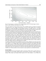
First, we can conclude from Eq. (6.13) that the dependence of the strain
rate upon the average particle size 2
r is a function with a minimum. There
is a particle size, under which the deforming dislocations move at the least
velocity. Indeed, if the value of 2
r is small the pre-exponential factor is large
and the exponent factor is close to unity. In this case, if the particle size
2
r increases, the exponent increases more rapidly than the pre-exponential
factor. Hence there is an optimal size of particles 2
r
0
, which is dependent on
T and σ. Taking the derivative and solving ∂V/∂(2
r)=0we find that for
EI437B superalloy at 973K and σ = 400MPa the value of 2
r
0
=12.2 nm. The
result fits the measured value 14 nm satisfactorily.
It is of importance to estimate the energy ∆U.
Taking the logarithm of Eq. (6.13) we obtain
∆U = −kT ln ˙ε +0.12τb
2
· 2¯r + kT ln
νb
3
0.24 · 2¯r
+ kT ln[f(c)N] (6.14)
It is essential to know the last term on the right-hand side of Eq. (6.14) in
order to calculate a mean activation energy ∆U.
Rae et al. [38] have measured the dislocation density in the crept CMSX-4
superalloy. The density of dislocations was estimated to be 2 × 10
12
m
−2
by
measuring the total length of dislocations in an area. One may reasonably
assume that the product of the concentration and the dislocation density will
be in the range 10
10
–10
12
m
−2
, most likely 10
12
m
−2
.
Applying Eq. (6.14) for tests of the same superalloy under two stresses σ
1
and σ
2
and denoting the sums of the first three terms as A
1
and A
2
one can
write
∆U = A
1
+ kT ln[f(c)N
1
] (6.15)
∆U = A
2
+ kT ln[f(c)N
2
] (6.16)
Thus, the logarithm of the ratio of the dislocation densities is given by
ln
N
2
N
1
=
A
1
− A
2
kT
(6.17)
6.5 Mechanism of Strain and the Creep Rate Equation 101
Tab. 6.3 The calculated activation energies of the elementary
deformation event in the γ
phase of superalloys. The values
of f (c)N that have been assumed (m
−2
) are shown above
columns 4 to 6.
σ
2
/σ
1
, ∆U, 10
−19
Jat.
−1
Ref.
T , K MPa/MPa N
2
/N
1
10
10
10
11
10
12
923 600/400 30.3 3.56 3.87 4.18 author
1023 280/80 115.1 3.68 4.01 4.33 35
973 360/280 6.0 3.97 4.28 4.59 37
1023 320/200 10.3 4.11 4.44 4.76 32
1173 280/120 32.0 4.45 4.82 5.19 author
1144 520/280 7.2 4.50 4.86 5.22 36
One can see from Table 6.3 that the dislocation density increases by one or
two orders when the applied stress is increased twofold or less.
In Table 6.3 the calculated values of the activation energy are presented.
The superalloys are listed in the order of increasing activation energy. The
experimental data from Figs. 6.5, 6.6 and Table 6.1 are used to calculate f(c)N.
If the dislocation density is assumed to be 10
12
m
−2
the activation energy
ranges from 4.18 × 10
−19
to 5.22 × 10
−19
Jat.
−1
.
The apparent activation energy of creep, ∆Q
app
was measured by Picasso
and Marzocca [39] for the IN-X750 superalloy
1)
. They used the technique of
differential temperature steps. The method is based on Eq. (1.4). A specimen
is subjected to a deformation under constant stress and temperature T
1
until
a given strain is reached. At this point the temperature is changed abruptly to
T
2
which may be above or below T
1
. The value of ∆Q
app
is calculated using
the relationship
∆Q
app
= −k
ln( ˙ε
2
/ ˙ε
1
)
(1/T
2
− 1/T
1
)
(6.18)
where ˙ε
1
is the initial strain rate at the temperature T
1
and ˙ε
2
is the final strain
rate at temperature T
2
. This method has an essential drawback: an instability
of structure during the temperature change results in too high measured
values of Q
app
. If the differential change of temperature did not modify the
substructure the authors [39] obtained Q
app
=5.08 × 10
−19
Jat.
−1
.
The energy of self-diffusion in Ni is (4.64 ± 0.21) × 10
−19
Jat.
−1
[22].
The data are averaged over results presented for temperatures from 953K to
1673K in seven publications. Thus, the value of the activation energy ∆U for
superalloys is somewhat greater than the energy of self-diffusion in nickel.
1) The activation energy of an elementary event of the high-temperature strain (creep) is denoted
differently by different authors, as Q, Q
c
, ∆Q
app
, ∆U.
102 6 High-temperature Deformation of Superalloys
Manonukul et al. [37] have proposed an expression for the dependence of
the strain rate on the volume fraction of the γ
phase of the form
f(c)=
(4π/3c)
1/3
− 2
(4π/3c)
1/3
(6.19)
However, the expression ceases to be valid for a γ
fraction in a superalloy
of more than 0.45 (Table 6.4).
Tab. 6.4 Dependence of the factor f(c) on the fraction of hardening phase.
c 0.10 0.15 0.20 0.25 0.30 0.35 0.40 0.45
f(c) 0.42 0.34 0.28 0.22 0.17 0.13 0.09 0.05
6.6
Composition of the γ
Phase and Mean-square Amplitudes of Atomic Vibrations
We have studied the composition and have measured the mean-square am-
plitudes of the atomic vibrations in solid solutions based on Ni
3
Al. The alloys
Ni
3
Al, Ni
3
(Al, Ti) and strengthening phases representing solid solutions of
different elements in the intermetallide of the type B
3
A were investigated
(Table 2.1). The γ
phases were extracted electrolytically from aged superal-
loys.
An X-ray technique for the measurement of mean-square amplitudes sepa-
rately for each of the two sublattices of a γ
phase has been developed [17]. We
determined the chemical compositions of the γ
phases by chemical analysis
and X-ray diffractometer studies of the specimens were also carried out. We
measured the intensities, I, of the (100) and (200) reflections and compared
the ratios I
(100)
/I
(200)
with calculated values. The ratios have been calculated
for the distribution of all kinds of elements between the γ
sublattices, B and
A. The ratio under study is dependent on the average factors of the X-ray
scattering in the sublattices,
¯
f
B
and
¯
f
A
, respectively. The final formulas of
the phases have been established by us under the condition of a coincidence
of the experimental and calculated values of this ratio. The obtained data are
summarized in Table 6.5.
According to the obtained results Ti atoms occupy places in the sublattice
A (Fig. 6.1). Cr, Fe and Co atoms are located preferentially in sublattice B. Mo,
W and Nb partition between the two sublattices, but are mainly located in A.
There is a connection between the amplitudes of heat-induced atomic vibra-
tions and the forces of interatomic bonds in the crystal lattice of the hardening
γ
phase. It seems natural that the greater the vibration amplitude the greater