Steel Designer''''s Manual Part 12 pptx
Bạn đang xem bản rút gọn của tài liệu. Xem và tải ngay bản đầy đủ của tài liệu tại đây (1.12 MB, 80 trang )
0.2 in
n
-4-
I
12 mm gusset
/
plate
-+-
0.5 m
L
1.2 m
0.2 m
100
430
100
0.Sm
— I
828 kN 350 kN
Ehk
1.5m
Worked examples 839
Subject Chapter ref.
Design code Sheet no.
Made by
Checked by
27
1
FOUNDATION
EXAMPLE 1
HB
BS5950: Part 1 GWO
The
Steel Construction
Institute
Silwood Park, Ascot, Berks SL5 7QN
Subject Chapter ref.
Design code Sheet no.
Made by
Checked by
27
1
FOUNDATION
EXAMPLE 4
HB
BS 5950: Part 1
GWO
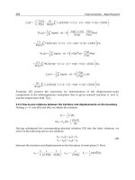
Problem
Design a built-up base for the valley stanchion of a double bay
crane shed that is shown belon. The stanchion comprises twin
406 ¥ 178 UB.
Taking moments about the tensile bolt, with n, the trial neutral axis
as 0.4m depth, and taking
Loading
f f N mm assu g f N mm
ccu cu
== =
()
0 6 12 20
22
. / min /
828 ¥ 1.5 - 350 ¥ 0.3 = C (2.0 - 0.2)
CkN=
¥- ¥
=
828 1 5 350 0 3
18
632
.
4.13.1
Steel Designers' Manual - 6th Edition (2003)
This material is copyright - all rights reserved. Reproduced under licence from The Steel Construction Institute on 12/2/2007
To buy a hardcopy version of this document call 01344 872775 or go to
840 Worked examples
Subject Chapter ref.
Design code Sheet no.
Made by
Checked by
27
1
FOUNDATION
EXAMPLE 1
HB
BS5950: Part 1
GWO
The
Steel Construction
Institute
Silwood Park, Ascot, Berks SL5 7QN
Subject Chapter ref.
Design code Sheet no.
Made by
Checked by
27
2
FOUNDATION
EXAMPLE 4
HB
BS 5950: Part 1
GWO
Taking n as 0.2m, C becomes 598kN and f
c
is 4.98N/mm
2
T is then: 598 + 350 - 828 = 120kN
To check, take moments about C
The relative stiffness of the base plate and channels will determine
the point of application of the compressive force. As an alternative
therefore assume the lever arm to be equal to the bolt centres and
the centre of compression at the bolt line with appropriate stiffen-
ing added at this point.
This is the minimum value of n for concrete strength of 20 N/mm
2
.
Design of channels & gusset
M = 669 ¥ 300/10
3
= 200.7kNm
Use 2/229 ¥ 89 ¥ 32.76 RSCs, M
cx
= 95kNm
These are satisfactory by inspection since the gussets and base plate
acting compositely would also make a contribution.
The internal stiffener and base plate would similarly be designed
as a composite member taking the maximum outstand given in
Table 11 of BS 5950.
CkN
TkN
n
Nmm
mm
=
¥- ¥
=
=+-=
=
¥
¥
=
828 1 5 350 0 3
17
669
669 350 828 191
669 10
630 12
88
3
2
.
/
828 0 4 350 1 6
19
120 4
¥- ¥
=
.
.kN
fNmm
c
=
¥
¥¥
=
632 10
04 06 10
263
3
6
2
./
Steel Designers' Manual - 6th Edition (2003)
This material is copyright - all rights reserved. Reproduced under licence from The Steel Construction Institute on 12/2/2007
To buy a hardcopy version of this document call 01344 872775 or go to
3
B
Worked examples 841
Subject Chapter ref.
Design code Sheet no.
Made by
Checked by
27
1
FOUNDATION
EXAMPLE 1
HB
BS5950: Part 1 GWO
The
Steel Construction
Institute
Silwood Park, Ascot, Berks SL5 7QN
Subject Chapter ref.
Design code Sheet no.
Made by
Checked by
27
3
FOUNDATION
EXAMPLE 4
HB
BS 5950: Part 1
GWO
The base plate panel between the stiffeners should be checked using
the Pounder expressions given in Chapter 30 as follows – the panel
is shown below.
Base plate
K
me
, the Pounder expression for moment, in the centre of the long
edge, when all four edges are encastre, is given below:
w
me
, the ultimate load intensity is given by:
The plate thickness of 16mm is therefore satisfactory.
f N mm cf f N mm for n m
cc
=
¥
¥
===
669 10
600 200
558 498 02
3
22
./,. ./ .
W
t
K
me
me
=
¥¥ ¥
¥
[]
275 12 1 2
6 170
2
2
.
KK k K
me
=+-
()
+-
()
È
Î
Í
˘
˚
˙
=
1
11
35
1
79
141
1
0 9796
2
.
L
B
K
==
=
+
=
406
170
238
238
238 1
097
4
4
.
.
.
.
Steel Designers' Manual - 6th Edition (2003)
This material is copyright - all rights reserved. Reproduced under licence from The Steel Construction Institute on 12/2/2007
To buy a hardcopy version of this document call 01344 872775 or go to
Chapter 28
Bearings and joints
by STEPHEN MATTHEWS
842
28.1 Introduction
28.1.1 Movement
All structures move to some extent. Movements may be permanent and irreversible
or short-term and possibly reversible. The effects can be significant in terms of the
behaviour of the structure, its performance during its lifetime, and the continued
integrity of the materials from which it is built.
Movements can arise from a variety of sources:
(1) environmental: thermal, humidity, wind-induced.
(2) material properties: creep, shrinkage.
(3) loading: axial and flexural strains, impact, braking, traction, centrifugal forces.
(4) external sources: tilt, settlement, subsidence, seismic loads.
(5) use of the building: heating, cold storage.
(6) others: requirements for moving or lifting bridges, allowances for jacking pro-
cedures, during or after construction.
In general it is necessary to consider the behaviour of the structure at each point
in terms of its possible movement in each of three principal directions, together with
any associated rotations. The movements of a structure are not in themselves detri-
mental; the problems arise where movements are restrained, either by the way in
which the structure is connected to the ground, or by surrounding elements such as
claddings, adjacent buildings, or other fixed or more rigid items. If provision is not
made for such movements and associated forces it is possible that they will lead to,
or contribute towards, deterioration in one or more elements. Deterioration in this
context can range from, for example, cracking or disturbance of the finishes on a
building to buckling or failure of primary structural elements due to large forces
developed through inadvertent restraint.
Note that for bridges with total lengths of up to 60m, it is possible to dispense
with bearings and expansion joints through use of abutments and piers which are
designed to be integral with the bridge deck. Further guidance on this topic can be
found in Reference 1.
Steel Designers' Manual - 6th Edition (2003)
This material is copyright - all rights reserved. Reproduced under licence from The Steel Construction Institute on 12/2/2007
To buy a hardcopy version of this document call 01344 872775 or go to
Bearings 843
28.1.2 Design philosophies
In catering for movement of a structure, one of three methods can be adopted:
(1) Design the structure to withstand all the forces developed by restraint of move-
ment. This is possible with smaller structures (small-span bridges) or structures
which are comparatively flexible (portal frames, in the plane of the frame).
The method will avoid joints but may require the use of additional material in
construction.
(2) Subdivide the structure into smaller structurally stable units, each of which then
becomes essentially a structure in its own right, able to move independently of
the surrounding units. This principle is ideal for controlling those factors such
as thermal movement which are related to the size of the overall structure. In
many cases, the need for bearings as discrete elements can be eliminated. The
disadvantage lies in the need to provide joints between the various units of the
structure capable of accommodating all the anticipated relative movements
between the units, while at the same time fulfilling all the other requirements,
i.e. visual, practical, etc. It is, however, generally possible to achieve a balance
by subdividing the structure so that the movements at the joints between units
are kept relatively small, permitting the joints to be simple and economical
(possibly at the expense of larger numbers of joints).
(3) Subdivide the structure into fewer but larger sections, and make provision for
a smaller number of joints, each with larger movement capacity, and thus pos-
sibly more complex than those that would be used at (2). Examples are to be
found in bridges where use of the least number of road deck joints is prefer-
able both in terms of riding quality, and also in the minimization of long-term
maintenance requirements.
The need to restrict strains on elements and thus to protect finishes will lead to
the adoption of the second of the above methods for design of building structures.
Bridges, for reasons cited above, are more frequently designed adopting the third
method.
28.2 Bearings
28.2.1 Criteria for design and selection
28.2.1.1 Form of the unit
Choice of form depends on several criteria:
(1) Physical size limitations. The space available in the structure for the bearing.
As bearings are subject to more wear than other parts of the structure they
Steel Designers' Manual - 6th Edition (2003)
This material is copyright - all rights reserved. Reproduced under licence from The Steel Construction Institute on 12/2/2007
To buy a hardcopy version of this document call 01344 872775 or go to
844 Bearings and joints
may have a shorter life and consequently this space should include allowance
for access, inspection, maintenance and possible replacement.
(2) Bearing pressure. The allowable bearing pressure on the materials above and
below the bearing will dictate the minimum size of the top and bottom faces
of the bearing unit.
(3) Loading. The magnitude of the design load to be withstood by the bearing in
each of the three principal directions will govern the form and type of the
bearing. For each direction the maximum and minimum load should be
considered at ultimate limit state, serviceability limit state or working load
depending on the requirements of the design. In each case co-existent load and
movement effects should be considered, together with a check for the exis-
tence of any load combinations which would act so as to separate the compo-
nents of the bearing (e.g. uplift). For bearings carrying both horizontal and
vertical loads it is common that the design of the bearing requires a minimum
vertical load to be present to ensure satisfactory performance under horizon-
tal loads.
(4) Rotations. The magnitude of the maximum anticipated rotations in the three
principal directions should be considered. For certain types of bearing (e.g.
elastomeric bearings) there exists an interaction between maximum load-
carrying capacity and rotation/translation capacity, so that it may be necessary
to consider co-existent effects under loading (3) and movement (5).
(5) Movements. Provision for maximum calculated movements can affect the size
of the moving parts of the bearing and thus the overall size of the unit.As with
rotations, the design of certain types of bearing is sensitive to the interaction
of movement and loading requirements.
(6) Stiffness (vertical, rotational or translational). Certain structures may be sensi-
tive to the deformation which occurs within the bearing during its support of
the loads. The various types of bearing have different stiffness characteristics
so that an appropriate form can be selected.
(7) Dynamic considerations. Any particularly onerous dynamic loadings on the
structure will have to be considered. Certain types of bearings (e.g. elastomeric
bearings) have damping characteristics which may be desirable in particular
instances, such as vibration of footbridges or machine foundations.
(8) Connections to structure. The form of connection of the bearing to the struc-
ture requires careful consideration of the materials involved and the need
for installation, maintenance and replacement of the bearing. In addition,
bearings are frequently at a position in the structure where different forms of
construction meet, perhaps constructed by different contractors. In this case,
it is necessary to ensure that surrounding construction is properly detailed so
that design requirements for load transfer are achieved.
(9) Use of proprietary bearings. Many types of bearings are commercially avail-
able. These range from items which are available ‘off the shelf’ to more spe-
cialized units which may be designed and proven, but which are only produced
to order. It is often appropriate for bearings to be individually designed to
meet a particular need in situations where proprietary types may not be suit-
Steel Designers' Manual - 6th Edition (2003)
This material is copyright - all rights reserved. Reproduced under licence from The Steel Construction Institute on 12/2/2007
To buy a hardcopy version of this document call 01344 872775 or go to
Bearings 845
able. In these instances the engineer has the option of designing the units using
available literature (see references to Chapter 28) and perhaps incorporating
standard bearings from a manufacturer as components of a completed assem-
bly or alternatively engaging a recognized manufacturer to design and produce
the item as a special bearing. For straightforward applications such as may be
required on a short single-span bridge, it may be worthwhile investigating the
relative costs of a simple fabricated bearing compared with the equivalent pro-
prietary unit. Bearings (particularly ‘special’ bearings) can prove to be a large
item of expenditure in a structure and an estimate of the costs involved should
be made early in the design stage.
(10) Summary of design requirements. Before selecting a particular bearing it is
suggested that a summary of all relevant parameters is prepared.This can then
be used if necessary for submission to the bearing manufacturers for exami-
nation and recommendations as to particular bearing types. A typical format
for such a sheet is given in Table 9 of BS 5400: Section 9.1.
2
28.2.1.2 Materials
Generally materials fall into three groups:
(1) those able to withstand high localized contact pressures e.g. steel.
(2) those able to withstand lower contact pressures but having a low coefficient of
friction; these slide easily in a direction perpendicular to the direction of the
pressure and thus accommodate translational movement, e.g. polytetrafluoro-
ethylene (PTFE).
(3) those able to withstand contact pressure and also to accommodate translational
or rotational movements by deformation of the material (e.g. elastomers).
Certain of these materials may be confined within a steel cylinder in order to
increase their compressive resistance.
(a) Mild or high-yield steel
The coefficient of friction of steel on steel is of the order of 0.3 to 0.5, unless con-
tinuously lubricated; in order to provide for movement alternative arrangements
are usually necessary. Traditionally this has been through the use of single or
multiple rollers or knuckles. Rollers will permit translation in one direction and,
if a single roller is used, rotation about an axis perpendicular to that direction.
Knuckles permit rotation about one axis only. Rotation in two directions may be
achieved using spherical-shaped bearing surfaces.
The allowable pressures between surfaces for steel on steel contact depend upon
the radii of the two surfaces and the hardness and ultimate tensile strength of the
material used. BS 5400: Section 9.1
2
gives expressions for design load effects in such
Steel Designers' Manual - 6th Edition (2003)
This material is copyright - all rights reserved. Reproduced under licence from The Steel Construction Institute on 12/2/2007
To buy a hardcopy version of this document call 01344 872775 or go to
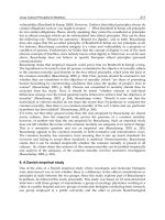
note! (i) if pure ptfe used unlubricated, use
2 x coefficient of friction shown
(ii) if filled ptfe used, use 4 x values
I I I I I I
510 15 20 25 30
bearing stress (N/mm2)
0.08
coefficient
0.06
of friction
0.04
0.02
846 Bearings and joints
cases. As load-carrying requirements increase, the use of steels with greater hard-
ness is dictated. This can be achieved by use of high-grade alloy steels of various
compositions. For design purposes, Table 2 of BS 5400: Section 9.1
2
gives indicative
values of coefficients of friction of between 0.01 and 0.05 for steel roller bearings.
(b) Stainless steel
Stainless steel is frequently used in strip or plate form to provide a smooth path for
sliding surfaces. It is important to utilize a material for the sliding surface which will
not deteriorate and adversely affect the coefficient of friction assumed for design
of the structure.A typical arrangement is a polished austenitic stainless steel surface
sliding against dimpled PTFE.
(c) Polytetrafluoroethylene (PTFE)
PTFE has good chemical resistance and very low coefficients of static and dynamic
friction. Unfortunately, pure PTFE has a low compressive strength, high thermal
expansion and very low thermal conductivity.As a consequence it is frequently used
in conjunction with ‘filler’ materials which improve these detrimental effects without
significantly affecting the coefficient of friction.
The coefficient of friction varies with the bearing stress acting upon it. BS 5400:
Section 9.1
2
gives the relationship shown in Fig. 28.1 for continuously lubricated
pure PTFE sliding on stainless steel.
Lubrication of the pure PTFE is commonly achieved by means of silicone grease
confined in dimples which are rolled on to the surface of the material. References
2 and 3 give further guidance on the restrictions on shape, thickness and contain-
ment on the PTFE and stainless steel components.
In preliminary design and assessment of forces on structures using PTFE sliding
Fig. 28.1 Coefficient of friction for continuously lubricated pure PTFE
Steel Designers' Manual - 6th Edition (2003)
This material is copyright - all rights reserved. Reproduced under licence from The Steel Construction Institute on 12/2/2007
To buy a hardcopy version of this document call 01344 872775 or go to
D
(a)
(b)
Bearings 847
bearings, a figure of 0.06 is usually assumed for the coefficient of friction, and the
value is checked later when the bearing selection is complete.
(d) Phosphor bronze
For particular applications, such as bearing guides, phosphor bronze may be used,
BS 5400: Section 9.1 suggests a coefficient of friction of 0.35 for phosphor bronze
sliding on steel or cast iron.
(e) Elastomers
An elastomer is either a natural rubber or a man-made material which has rubber-
like characteristics. Elastomers are used frequently in bearings; they either consti-
tute the bulk of the bearing itself or act as a medium for permitting rotation to take
place (see sections 28.2.2.2 and 28.2.2.3(7)).
Elastomers are principally characterized by their hardness, which is measured in
several ways, the most common of which is the international rubber hardness
(IRHD). This ranges on a scale from very soft at 0 to very hard at 100. Those elas-
tomers used in bearings which are to comply with BS 5400: Part 9 have hardnesses
in the range 45 IRHD to 75 IRHD.
The tensile capacity of most elastomers is considerable.As an illustration BS 5400:
Part 9 specifies a minimum tensile elongation at failure of between 300% and 450%
depending on IRHD.
When considering the behaviour of a block of elastomer under vertical com-
pression it is assumed that the material is securely bonded to top and bottom loading
plates. In this case (which is representative of most bearing situations) the vertical
behaviour is related to the material’s ability to bulge on the four non-loaded faces
and is expressed in terms of the shape factor for the block, which is the ratio of the
loaded area to the force free surface area (see Fig. 28.2).
S
LB
tL B
S
D
t
=
+
()
=
2
4
for a rectangle
for a circle
Fig. 28.2 Elastomeric bearing dimensions for (a) a rectangular block, (b) a circular block
Steel Designers' Manual - 6th Edition (2003)
This material is copyright - all rights reserved. Reproduced under licence from The Steel Construction Institute on 12/2/2007
To buy a hardcopy version of this document call 01344 872775 or go to
stress
dissipated energy
9
strain
area of loop
'•
_________________
848 Bearings and joints
The vertical stiffness of the block is significantly reduced if the loaded faces can
slip laterally.
The shear stiffness of a block of elastomer bonded to top and bottom plates is
more or less linear and independent of shape factor. A detailed treatment of these
effects is given in References 4 and 2.
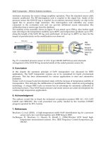
An important property of elastomers is related to the fact that the strain in the
material tends to lag behind the stress which causes it. As a consequence, some of
the energy input during deformation is dissipated within the bearing as heat. A
typical plot of stress versus strain for an elastomer is shown in Fig. 28.3. The energy
lost as heat in one loading cycle is represented by the area of the loop.
This effect, known as hysteresis, has two implications:
(1) it can result in a build-up of heat in the bearing under dynamic loading
conditions,
(2) if appropriately sized it can be used to act as a form of damping device to the
structure.
The sensitivity of the elastomer to dynamic loading depends upon both the fre-
quency of the applied stress and the temperature, as elastomers exhibit hardening
at low temperatures.
Elastomers are prone to creep and are sensitive to attack by atmospheric oxygen
and ozone, petrol and radiation from nuclear sources.They are not suitable for oper-
ation in temperatures above 120°C.
A more detailed discussion of these aspects is given by Long,
5
and limits are given
for their control in practice by BS 5400.
2
(f) Concrete
The concept of the use of a small, highly contained block of concrete as a hinge has
been employed in the form of the Freysinnet hinge or the Mesnager hinge. Details
of these are given in Reference 6.
Fig. 28.3 Energy loss in elastomer
Steel Designers' Manual - 6th Edition (2003)
This material is copyright - all rights reserved. Reproduced under licence from The Steel Construction Institute on 12/2/2007
To buy a hardcopy version of this document call 01344 872775 or go to
Bearings 849
28.2.2 Types of bearing
28.2.2.1 General
Structural bearings can be broadly divided into two types: elastomeric and mechan-
ical. Elastomeric bearings comprise blocks of elastomeric material reinforced as
necessary with other materials. They can be made to accommodate movement by
shearing of the elastomer block. Mechanical bearings are generally formed from
metal and employ sliding surfaces of PTFE to achieve any necessary movement
capabilities. It should be noted that the above divisions are not exclusive as, for
example, some bearings are commercially available which employ elastomer blocks
with sliding surfaces which cater for larger movements than could be accommo-
dated by shearing of the block, but which do not merit the larger expense of a
mechanical bearing.
In the following sections the principal types of bearing are briefly described.
28.2.2.2 Elastomeric bearings
Elastomeric bearings rely for their operation on the interaction between vertical
load, rotation and translation. As a consequence, design of most elastomeric bear-
ings must be carefully checked. Large proprietary ranges are available, and although
load tables of the various capacities are published by manufacturers, it is prudent
to ask the supplier to confirm that the selected bearing is suitable for the load/move-
ment conditions under which it will be used. The basis of design of these bearings
is related to controlling strains and stresses in the elastomer and any reinforcing
material and ensuring that the bearing does not deform excessively, become un-
stable, lift off, or slip under the anticipated design effects. Further guidance on
this subject is given in BS 5400: Part 9.1
2
and by Long.
5
The latter reference also
gives a detailed discussion of the properties of elastomers.
Bearing types are:
(1) Rubber pad or strip bearings. As the name implies, these bearings consist simply
of a block or strip of elastomer. They have the advantage of being inexpensive
and simple although their load-carrying and movement capability is limited.
(2) Fabric-reinforced bearings. In order to increase the capabilities of the simple
pad bearing, use is made of fabric (e.g. compressed cotton duck) to reinforce
the elastomer.Movement in these bearings is usually provided by use of a PTFE
surface bonded to the top of the block and sliding against a stainless steel plate
attached to the underside of the superstructure. In this manner, the elastomer
is used to provide rotational capability only, rather than rotation and movement
as in the case of other elastomeric bearings.
(3) Elastomeric-laminated bearings. This type of bearing consists of a block of elas-
tomeric material reinforced with steel plates to which the elastomer is also
Steel Designers' Manual - 6th Edition (2003)
This material is copyright - all rights reserved. Reproduced under licence from The Steel Construction Institute on 12/2/2007
To buy a hardcopy version of this document call 01344 872775 or go to
C,,
C,,
C,)
850 Bearings and joints
bonded.The characteristics of the bearings can be varied considerably by alter-
ation of the size, shape and disposition of the layers as well as the usual param-
eters of bearing plan area and thickness. Generally, these bearings are either
‘fixed’ for translation by means of a steel dowel passing through the bearing
layers (Fig. 28.4(a)) or ‘free’ bearings which permit translation and rotation by
deformation of the bearing (see Fig. 28.4(b)). This type of bearing is capable of
carrying quite substantial loadings and movements and has the benefit of being
cheaper than mechanical bearings.
28.2.2.3 Mechanical bearings
(1) Roller (Fig. 28.5(a)). The earlier and more traditional forms of bearing com-
prised single or multiple steel rollers sandwiched between upper and lower steel
plates. Single rollers will allow for longitudinal movement and rotation about
the axis of the roller, while at the same time carrying comparatively high
vertical loads, hut will not permit transverse rotation or movement. Bearings of
very large capacity have been produced by use of special alloy steels to form
the contact surfaces. Note that bearings which utilize multiple rollers will not
allow rotation about an axis parallel to the axis of the rollers. Rollers are some-
times used enclosed in an oil bath or grease box to exclude deleterious matter.
Other forms of bearing have, to a large extent, supplanted the use of rollers for
the most common applications.
(2) Rocker (Fig. 28.5(b)). Rocker bearings will not permit translational movement.
The bearings may be cylindrical or spherical on one surface with the other
surface flat or curved. In the cylindrical form there is no provision for trans-
verse rotation, which may have consequences for design of the structures above
and below the unit. Rocker bearings usually incorporate a pin or shear key
between the two surfaces to maintain relative position.
Fig. 28.4 Two types of elastomeric bearing: (a) fixed, (b) free
Steel Designers' Manual - 6th Edition (2003)
This material is copyright - all rights reserved. Reproduced under licence from The Steel Construction Institute on 12/2/2007
To buy a hardcopy version of this document call 01344 872775 or go to
U)
U)
—
CD
2.
n
.
C Pl
- 0
C/,
—
2.
3—
0
0
0
C
s
O()
Jq
a.
U)—
C
C)
Bearings 851
(3) Knuckle bearings (Fig. 28.5(c)). These are similar to rocker bearings.
(4) Leaf bearings (Fig. 28.5(d)).These are formed of leaves of steel with a common
pin.They will carry large vertical loads and permit large rotations about the axis
Fig. 28.5 Mechanical bearings: (a) single/multiple roller, (b) cylindrical/spherical rocker, (c)
cylindrical knuckle, (d) knuckle leaf, (e) swing link, (f) spherical – with sliding top
plate, (g) cylindrical PTFE bearings combined to form ‘anticlastic’ bearing,(h) ‘pot’
bearing which can have sliding top plate similar to (f)
Steel Designers' Manual - 6th Edition (2003)
This material is copyright - all rights reserved. Reproduced under licence from The Steel Construction Institute on 12/2/2007
To buy a hardcopy version of this document call 01344 872775 or go to
852 Bearings and joints
of the pin but not transversely. They have the benefit that they can be designed
to resist uplift. It should be noted, however, that they are unlikely to be any-
thing other than produced to order and that there may be other means of con-
trolling comparatively small uplifts (e.g.‘pot’ type bearing with separate vertical
restraints). Leaf bearings have been used in suspension bridges to form the
swing link bearings which are necessary to cater for large movements and uplifts
(Fig. 28.5(e)).
(5) Spherical (PTFE, circular) (Fig. 28.5(f)). These comprise a spherical lower
surface which is lined with PTFE and a matched upper spherical surface of
aluminium or stainless steel. This arrangement allows considerable rotation
capacity in all directions. Horizontal translation is frequently achieved using
another (flat) sliding surface above the upper part of the bearing.
An important consideration with spherical bearings is that in order to
withstand any horizontal loads it is necessary to have a minimum co-existent
vertical load to prevent instability.
Spherical bearings are capable of carrying high vertical loads and also permit
higher rotations than many other types.
(6) Cylindrical (PTFE) ‘anticlastic’ bearings (Fig. 28.5(g)). These are similar in
concept to rocker bearings but instead of using (for example) steel on steel
bearing surfaces they have enlarged bearing areas which are coated with PTFE
on one surface and stainless steel or aluminium on the other. This produces
a bearing with high rotation capabilities about an axis as well as high load-
carrying capacity. One unit can be combined with another similar arrangement
to provide rotation about an axis at right angles to the first and also with a
sliding plate arrangement to provide translational capability.
(7) Disc or ‘pot’ (Fig 28.5(h)). These are often of similar proportions to spherical
hearings but instead of a sliding spherical surface being used to provide rota-
tion capability, a disc of elastomeric material is used, confined in a cylindrical
pot. Loading is applied to the surface of the disc via a closely fitting steel piston.
Under these conditions, the confined elastomer is in a near fluid state, and
permits rotation in all directions without significant resistance. Sliding is
achieved by means of a PTFE/sliding surface above the piston, in a similar
manner to spherical bearings. Disc bearings are popular for many applications,
as they tend to be cheaper than spherical bearings but can carry higher
loadings than elastomeric-laminated bearings of comparable plan area. They
have rotation capabilities intermediate between spherical and laminated
bearings.
(8) Fabricated. Fabricated bearings have become less popular largely through the
availability of a wide range of proprietary units. They are used for footbridges
and temporary works applications. There is, however, no reason why properly
designed fabricated bearings should not be used to support a structure, partic-
ularly, say, for a fixed bearing where there is no requirement for sliding surfaces.
Guidance on design of bearings is given in References 2–9.
(9) Special. Special bearings will always be required for particular locations.
Perhaps the most common demands are for:
Steel Designers' Manual - 6th Edition (2003)
This material is copyright - all rights reserved. Reproduced under licence from The Steel Construction Institute on 12/2/2007
To buy a hardcopy version of this document call 01344 872775 or go to
Bearings 853
(a) bearings which will resist horizontal loads only in order to restrain the struc-
ture in the horizontal plane, but without providing any vertical support (see
section 28.2.4.2(3))
(b) bearings which will withstand uplift under certain loading conditions.
Uplift bearings can be special versions of normal proprietary bearing types, or
can use a proprietary bearing set in a subframe which controls the tendency to uplift
within prescribed limits adopted in consultation with the bearing manufacturer.
28.2.3 Use of bearings
28.2.3.1 General
The parameters which dictate the form of the bearing as a unit are discussed in
section 28.2.1. It is also necessary to consider the action of the bearing in the broader
concept of the behaviour of the two elements of structure which the unit connects.
28.2.3.2 Fixings
Various forms of fixings are utilized to connect bearings to the structure. These
include:
(1) shear studs, usually in conjunction with a subsidiary plate which is tapped to
receive the bearing fixing bolts,
(2) square or cylindrical dowels, tapped to receive the bearing fixing bolts,
(3) direct bolting of the bearing to the structure.
In all forms it is desirable to allow for tolerances in the processes of installation
and possible need for replacement of the bearing. The system shown in Fig. 28.6
allows for support of the bearing during fine adjustment, but requires large jacking
Fig. 28.6 Bearing fixing
Steel Designers' Manual - 6th Edition (2003)
This material is copyright - all rights reserved. Reproduced under licence from The Steel Construction Institute on 12/2/2007
To buy a hardcopy version of this document call 01344 872775 or go to
854 Bearings and joints
capability (possibly more than a continuous structure could accommodate) to
remove it.
In bearings subjected to dynamic loadings such as machine foundations, it is nec-
essary to ensure that the fixings are vibration-proof.
28.2.3.3 Effect on the structure
The elements of the structure above and below the bearing are affected by the type
of bearing, which can be classified as:
(1) fixed – not permitting movement in any horizontal direction,
(2) guided – movement, constrained by guides of some form, to be in one horizon-
tal direction only,
(3) free – movement permitted in all horizontal directions,
(4) elastomeric, which may be laminated or not. These bearings can be ‘fixed’ by
means of steel dowels passing through them but are more often used ‘free’ in
all directions and their capability to generate forces when shearing takes place
is utilized to withstand horizontal loadings. If the whole structure is supported
on such bearings it effectively ‘floats’, with all horizontal loads shared by all
bearings. (See also section 28.2.4.2.)
If the bearings are fixed or guided, the neighbouring structure must be designed
for the forces arising from the restraints. Even when the bearing is free in a particu-
lar direction and movement is permitted, some forces are developed – either from
friction effects at the movement interfaces of a sliding mechanical bearing, or from
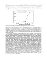
shearing deformation in the case of an elastomeric bearing (see Fig. 28.7(a)).
In addition to forces developed laterally, the effects of the eccentricities produced
by the movement must be allowed for,and also the rotation capability of the bearing
in the transverse direction (see Figs 28.7(b), (c) and (d)). It is possible to control
the extent of the additional eccentricity effects on a steel superstructure by use of
a sliding bearing inverted which transfers the eccentricity to the substructure, where
it may be more easily accommodated. In this case however care should be taken to
protect the sliding surfaces against falling dust, debris, etc. by use of a flexible skirt
enclosure.
28.2.3.4 Installation
Bearings must be correctly installed into the structure. The procedure will depend
upon the form of the structure above and below the bearing,and the type of bearing,
but in general care should be taken not to load the bearing significantly before
bedding materials between the bearing and the structure have fully cured, or to load
Steel Designers' Manual - 6th Edition (2003)
This material is copyright - all rights reserved. Reproduced under licence from The Steel Construction Institute on 12/2/2007
To buy a hardcopy version of this document call 01344 872775 or go to
centre of pressure does not apparently
change but note reduction in effective
area — affects compressive stress of
bearing; additional forces F are generated
(a)
design superstructure
for eccentricity i.
design
for eccentricity
(b)
position
after
movement
V
V
bearings with
no transverse
rotation capacity
1
Ii
failure of bearing, or
structure, or both
(c) (d)
(
a
—.1—1.—a
no eccentricity
design
perstructure for
eccentricity a
on substructure
flexible' beam
Bearings 855
the bearing in a manner for which it has not been designed.A common cause of the
latter effect is the incorporation of temporary packs or shims into the bedding in
such a manner that they subsequently form hard spots under the bearing. (Note that
there is, however, no fault in principle with the concept of temporary packing pro-
vided that it is responsibly carried out.)
Factory-assembled bearings are usually provided with transit straps to prevent
inadvertent dismantling of the unit. When a significant irreversible movement is
anticipated at a bearing, due to shrinkage or prestressing for example, an allowance
for this movement may be pre-set in the factory.To allow for departure of the actual
structure temperature, when the bearings are set, from the mean temperature
assumed in design, it may be necessary to make alterations of the relative positions
of the fixed and moving elements of the bearing. For bridges, Lee
6
suggests times
when this may be most conveniently carried out – when the bridge temperature is
approximately equivalent to the air shade temperature. This can be taken as:
Fig. 28.7 Effect of bearing on structure: (a) elastomeric, (b) roller, (c) sliding, (d) need for
transverse rotation capacity
Steel Designers' Manual - 6th Edition (2003)
This material is copyright - all rights reserved. Reproduced under licence from The Steel Construction Institute on 12/2/2007
To buy a hardcopy version of this document call 01344 872775 or go to
856 Bearings and joints
(1) concrete bridges: 0900 BST ± 1 hour each day,
(2) steel bridges: at about 0400 to 0600 BST each day during the summer, and at
any time on ‘average’ days during the winter.
Further guidance on bridge temperatures is given in Reference 10.
Frequently bearings are incorporated into the structure using a bedding layer
above and below the unit, typically of 25mm thickness, which allows some toler-
ance in fixing of the bearing and will also permit final adjustment of the levels of
the structure above during construction.The form of the bedding may be ‘dry pack’,
trowelable or pourable material. Epoxy resin, sand/cement, sand/epoxy, or
sand/polyester compounds are commonly used.The same material may also be used
for filling the spaces around fixing devices once final positioning has been carried
out.
28.2.4 Assemblies of bearings
28.2.4.1 General
The selection and use of bearings of various types has been discussed in terms of
the individual units. The behaviour of the structure or substructure as a whole will
now be considered, and the use of the four principal forms of bearing to control
movement illustrated.
28.2.4.2 Structures straight in plan
As an example, the movement of a typical bridge deck will be considered in the
horizontal plane, although the principles involved can equally be applied in other
directions.
The four forms of bearing commonly available are given in section 28.2.3.3.
Consider the bridge deck shown in plan in Fig. 28.8.
The deck vertical loading arises from dead and live loads, from which maximum
and minimum values of bearing loads can be derived at each position. Longitudi-
nal loading on the deck will arise from wind loads, braking and traction of vehicles,
and also from the manner in which the chosen restraint system accommodates
Fig. 28.8 Straight bridge deck
Steel Designers' Manual - 6th Edition (2003)
This material is copyright - all rights reserved. Reproduced under licence from The Steel Construction Institute on 12/2/2007
To buy a hardcopy version of this document call 01344 872775 or go to
t.)
<•)
(.1
a
(7'
m)w> mw>
I.l
i:i
a
• •
1.1.
• N) • •
ii®ii
- .•I.l.•
•.H a
•.i
•
.1.1.
•
(P
•
•.
•
00000
00000
00000
HO
ODD
00000
Bearings 857
movements. Forces from similar effects are generated in the transverse direction
also.
Thermal expansion and contraction of the deck is frequently the predominant
reversible movement. This can normally be considered to act radially from a par-
ticular fixed point on the deck. The options for bearing arrangement are many, but
three typical layouts are given in Fig. 28.9(a), (b) and (c). It should be remembered
that whether a bearing accommodates horizontal movement through PTFE/sliding
or by shearing of an elastomer block a horizontal force (due to friction or shear
respectively) will be generated, and the bearing system should be arranged so that
wherever possible these forces cancel one another out, and so minimize the net
horizontal force to be resisted by the substructure.
(1) In Figure 28.9(a) all the bearings are elastomeric with no fixed bearings. The
horizontal loads in both directions are shared between all bearings and the
structure ‘floats’.
Thus all substructures will be loaded when horizontal loads or expansion/
contraction occur. This system is economic, but is limited by the maximum
capabilities of the bearings in rotation, load, and movement.
(2) In Fig. 28.9(b) all the bearings are mechanical (typically spherical or pot bear-
ings). Line ‘C’ provides fixity in the transverse direction. Line 1 provides fixity
in the longitudinal direction. All longitudinal forces from external sources are
taken at abutment 1, together with longitudinal forces arising from friction at
Fig. 28.9 Typical bearing layouts for straight bridge decks: (a) all elastomeric, (b) all
mechanical (i), (c) all mechanical (ii)
Steel Designers' Manual - 6th Edition (2003)
This material is copyright - all rights reserved. Reproduced under licence from The Steel Construction Institute on 12/2/2007
To buy a hardcopy version of this document call 01344 872775 or go to
fixed
(a)
(b)
858 Bearings and joints
bearings on piers 2 to 5. At each pier transversely lateral loads are taken by ‘C’
line bearings. Friction forces due to transverse expansion, etc. will tend to cancel
one another out.
(3) The arrangement in Fig. 28.9(c) is better for longitudinal effects than that in Fig.
28.9(b) as friction forces in this direction tend to cancel one another out. It has
the disadvantage that external loads are transmitted to an intermediate pier
rather than an abutment. The forces due to movement of the deck are mini-
mized in both horizontal directions. Occasionally, the line of fixed or guided
bearings with both horizontal and vertical capability such as at ‘C’ may be
replaced by two lines, one with bearings with vertical capability only, and one
with bearings with horizontal capability only.
28.2.4.3 Structures curved in plan
If the structure shown in Fig. 28.9(b) is curved in plan, then any expansion or con-
traction movements longitudinally are accompanied by lateral movements also.This
effect can be controlled in two ways:
(1) set the bearing guides to permit radial expansion from a fixed point on the
structure,
(2) set the bearing guides tangential to the plan curvature, and so constrain the
structure to follow this line when it moves (see Fig. 28.10).
In radially-guided structures the accuracy of setting out and alignment becomes
more critical as the distance from the fixed point increases. In tangentially-guided
structures, the structure is constrained to move along a particular path, and the
horizontal forces developed in so doing must be taken into account in the design of
the structure and supports.
It should be noted that frequently bearings which are nominally ‘guided’ are
manufactured with a gap tolerance at the guides. The actual value of this tolerance
should be checked with the manufacturer of the particular bearing, but a value of
0.5mm is typical.This tolerance can have a significant effect on the permissible accu-
Fig. 28.10 Curved bridge deck: (a) radially-guided, (b) tangentially-guided
Steel Designers' Manual - 6th Edition (2003)
This material is copyright - all rights reserved. Reproduced under licence from The Steel Construction Institute on 12/2/2007
To buy a hardcopy version of this document call 01344 872775 or go to
Bearings 859
racy of setting out of radially-guided structures, and the magnitude of the forces
developed in tangentially-guided structures.
7
28.2.4.4 Structures with fixed bearings and flexible supports
An alternative to the use of systems of guided bearings is to provide fixed bearings
at more than one (possibly all) supports. In this case the supporting structures (e.g.
bridge piers) have to be designed to flex and accommodate the necessary move-
ments.They also have to cater for the forces developed by these movements in addi-
tion to any other design loading effects.This arrangement may be appropriate when
it is required to share horizontal load effects over several supports, but it should be
noted that replacement of the bearings may be more difficult owing to horizontal
loads which may be locked into the bearing/support arrangement.
28.2.4.5 Other considerations
(1) Wedging action. It is possible to utilize a form of ‘wedging action’ to resist
horizontal loadings by setting two (usually elastomeric) bearings on planes
inclined to one another as shown in Fig. 28.11. Equally, it is also possible to
develop the action inadvertently by errors in bearing setting out, and thus
attract more loading than that for which the unit is designed.
4,5,7
(2) Shock transmission units (STUs). Although not strictly bearings, these units can
be utilized in conjunction with bearings to distribute certain components of
loading to other parts of the structure. The units typically consist of a cylinder
filled with putty-like material which is acted on by a piston with a hole in it
through which the putty can flow. Slow, steadily applied forces such as thermal
expansion forces will cause the putty to flow from one side of the piston to the
other, and allow dissipation of the force through movement. Rapidly applied
forces such as seismic loads, braking loads, or wind gusts are too fast to allow
the flow to occur,and the unit therefore effectively transmits this ‘shock’ loading
without significant movement.A description of the use of these devices is given
in Reference 9.
Fig. 28.11 Wedging action
Steel Designers' Manual - 6th Edition (2003)
This material is copyright - all rights reserved. Reproduced under licence from The Steel Construction Institute on 12/2/2007
To buy a hardcopy version of this document call 01344 872775 or go to
860 Bearings and joints
28.3 Joints
28.3.1 General
The form of joints in a structure will vary to suit particular requirements at each
position. The basic parameters to be considered in derivation of a joint detail are
discussed below, although they are not all appropriate to every situation. Despite
the fact that significant differences exist in the final application, many of the factors
involved in joint design are common to both buildings and bridges. Joint detailing
and construction is considerably facilitated by the many forms of proprietary
sealants, gaskets, and fillers that are now commercially available for use as compo-
nents, as well as complete prefabricated units which may be used in particular appli-
cations. The manufacturers of these products will generally be able to supply
technical information on their products, and also to give guidance as to the suit-
ability of items for use in particular applications.
28.3.2 Basic criteria
28.3.2.1 Form of the structure
The form of the structure, and the location and orientation of the joint within the
structure, will dictate to a large extent the arrangement of the detail. The basic
categories of joint are:
(1) Wall joints. These may be vertical (e.g. expansion joint in a building or a bridge
substructure) or horizontal (e.g. joint between preformed cladding units on a
building façade).
(2) Floor/roof joints. Examples are expansion joints in a building, or road deck
joints in a bridge.
(3) Internal/external joints. This type of joint needs to be weather-proofed.
28.3.2.2 Material to be joined, and method of fixing
The material either side of the joint may be steel or aluminium cladding, concrete,
brickwork, blockwork, or various forms of surfacing.The detail of the joint will vary
considerably with the properties of the material and the method of fixing to be used.
It is important to note that this may affect the stage of construction at which the
joint is formed: e.g. PVC waterstops will need to be positioned before concreting of
the walls on either side of them takes place. Where it is anticipated that the joint
may need repair or replacement during the life of the structure (e.g. expansion joints
on heavily trafficked bridges) the fixings of the joint should allow for easy removal
and reinstatement.
Steel Designers' Manual - 6th Edition (2003)
This material is copyright - all rights reserved. Reproduced under licence from The Steel Construction Institute on 12/2/2007
To buy a hardcopy version of this document call 01344 872775 or go to
(a)
__
seal
filler
I,4
Ø7j7/7
/
seal
gasket
drain to
bottom
membrane
(PVC, thin metal, etc.)
Joints 861
28.3.2.3 Weather-resistance
It is important to consider the degree of weather-resistance required for a joint. In
this respect, joints can be classified (in a somewhat over-simplified form) into three
types (see Fig. 28.12(a), (b) and (c)):
(a) ‘Closed’ joint, with a filler material and exterior sealant,
(b) ‘Closed’ joint, with a compressible gasket and exterior sealant,
(c) ‘Open’ joint, with a flexible membrane seal, and arrangements to drain rain-
water, etc. from the inside surfaces of the joint which are ‘open’ to the weather.
Where appropriate, arrangements should be made at joints in buildings for con-
tinuity or sealing of insulation and vapour barriers, etc. to prevent formation of
condensation, or loss of heat.
In structures where there is likely to be water in contact with the structural
envelope, e.g. structures buried in ground which has a high water table, or water-
retaining structures, flexible waterbars are usually incorporated at construction and
movement joints. These have the effect of interrupting the path along which any
water present has to travel.
Figure 28.13(a), (b) and (c) are typical of wall details in reinforced concrete or
brickwork construction. A typical joint detail for steel cladding in a building is
Fig. 28.12 Weather-resistance of joints: (a) closed, with filler, (b) closed, with gasket,
(c) open, with membrane
Steel Designers' Manual - 6th Edition (2003)
This material is copyright - all rights reserved. Reproduced under licence from The Steel Construction Institute on 12/2/2007
To buy a hardcopy version of this document call 01344 872775 or go to
metal insulation
cladding
board
(d)
(e)
(exterior)
PVC/metal
(exterior)
compressible
filler
sealant
rubber or
PVC water bar
compressible
filler
(interior)
(a)
(b)
cv/AfrrArT
expansion joints
in inner & outer
skins staggered
(c)
it
1/
supporting
flexible joint
angle
to board
(possible)
compressible
water bar
filler
862 Bearings and joints
shown in Fig. 28.13(d), and Fig. 28.13(e) shows a detail suitable for a building roof
joint, or small bridge deck movement joint.
28.3.2.4 Direction of movement required
The direction of movement required at a joint will affect the form of the joint. All
likely movements should be evaluated, as restraint of unanticipated movements may
result in failure of the joint, or development of large restraint forces in the joint and
the adjacent structure.
Typical broad classifications of joint by movement requirements are given in Fig.
28.14(a), (b), (c) and (d).
In order to illustrate the nature of additional movements which can occur in a
structure, two particular cases relating to a bridge superstructure are considered (see
Fig. 28.15(a) and (b)).
Fig. 28.13 Typical joint details: (a) concrete walls, (b) concrete columns, (c) brick walls,
(d) cladding, (e) roof or bridge deck
Steel Designers' Manual - 6th Edition (2003)
This material is copyright - all rights reserved. Reproduced under licence from The Steel Construction Institute on 12/2/2007
To buy a hardcopy version of this document call 01344 872775 or go to