Steel Designer''''s Manual Part 14 potx
Bạn đang xem bản rút gọn của tài liệu. Xem và tải ngay bản đầy đủ của tài liệu tại đây (1.02 MB, 80 trang )
Mobility for non-mobile cranes
Non-mobile cranes can be made mobile by mounting them on rails. This has two
advantages: the positioning of the crane can be more easily dictated and controlled,
and the loads transmitted by the rails to the ground act in a precisely known loca-
tion. Many cranes have collapsed because of insufficient support underneath.
However, most rail-mounted crane failures have occurred from overloading. Where
the crane is to work over complex plant foundations the rail can be carried on a
beam supported, if necessary, on piles especially driven for the purpose. If the rail
is supported only by a beam on sleepers in direct contact with the ground, the load
can be properly distributed by suitable spreaders. In either case conditions must
be properly considered and designed for. Problems often occur when too much
faith is invested in the capability of the ground to support a mobile crane and its
outriggers.
Non-mobile cranes
Non-mobile cranes are generally larger than their mobile counterparts. They can
reach a greater height, and are able to lift their rated loads at a greater radius.
There are two main types of non-mobile crane: the tower crane and the (now
rare) derrick. Due to their great size, the cranes must arrive on site in pieces. Thus
the disadvantage of a non-mobile crane is that it has to be assembled on site. Having
been assembled, the crane must receive structural, winch and stability tests before
being put into service.
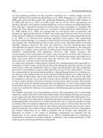
A tower crane with sufficient height and lifting capacity (see Fig. 33.11) has
several advantages:
(1) It requires only two rails for it to be ‘mobile’.These two rails, although at a wide
gauge, take up less ground space than a derrick.
(2) It carries most of its ballast at the top of the tower on the sluing jib/counter
balance structure, and so very much less ballast is needed at the bottom. Indeed,
in some cases, there is no need for any ballast at the tower base or portal.
(3) Because the jib of a tower crane is often horizontal, with the luffing of a derrick
jib replaced by a travelling crab, the crane can work much closer to the
structure and can reach over to positions inaccessible to a luffing jib crane.
(4) A tower crane is ‘self-erecting’ in the sense that, after initial assembly at or
near ground level, the telescoping tower eliminates the need for secondary
cranes.
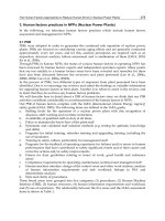
(5) As shown in Fig. 33.12 a tower crane can be tied into the structure it is erect-
ing, thus permitting its use at heights beyond its free-standing capacity.
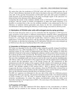
There exist several types of tower crane, e.g. articulated jib, luffing and saddle
cranes as illustrated in Fig. 33.13. It is essential that manufacturers or plant hirers
are consulted in order to make the most appropriate choice of crane.
Cranes and craneage 993
Steel Designers' Manual - 6th Edition (2003)
This material is copyright - all rights reserved. Reproduced under licence from The Steel Construction Institute on 12/2/2007
To buy a hardcopy version of this document call 01344 872775 or go to
12 500 kg
III V VI X
L5=55.Om
2900 kg
III
IV V X
/\A/\/\J\/\\/\V\7\J\/'\
L450.Om
3600 kg
V X
/\J\/\/\/\/\J/\/\/\/\(\
L345.Om
III IVX
/\/V\/\/\/W\/
L2.40.Om
III X
/\A/\/V'\
6300 kg
4 400 kg
300 kg
L I 35.0 m
Cranes for the stockyard
Stockyard cranes have to work hard. The tonnage per job has to be handled twice
in the same period of time, often with many fewer cranes. It is therefore important
that cranes be selected and cited carefully to ensure maximum efficiency.
33.8.3 Other solutions
If there is no suitable crane, or if there is no working place around or inside the
building where a crane may be placed, then consideration must be given to a special
mounting device for a standard crane, or even a special lifting device to do the work
of a crane, designed to be supported on the growing structure under construction.
In either event, close collaboration between the designer and erector members of
994 Erection
Fig. 33.11 Tower crane (courtesy of Delta Tower Cranes)
Steel Designers' Manual - 6th Edition (2003)
This material is copyright - all rights reserved. Reproduced under licence from The Steel Construction Institute on 12/2/2007
To buy a hardcopy version of this document call 01344 872775 or go to
I_! I' 111111 II —
the management team is of paramount importance. Conversely, inadequate com-
munication may prove problematic. Once the decision to consider the use of a
special lifting device has been made, a new range of options becomes available.
The most important of these is the possibility of sub-assembling larger and heavier
components, thereby reducing the number of labour hours worked at height.
This is particularly true in the case of bridgework, where substantial sums
would otherwise have to be expended on other temporary supports and stiffening.
A major disadvantage of special lifting devices is that the apparatus being con-
sidered is often so specialized that is unlikely to be of use on another job. Thus
Cranes and craneage 995
Fig. 33.12 Citigroup Tower, London showing tower cranes tied into the building (courtesy
of Victor-Buyck Hollandia)
Steel Designers' Manual - 6th Edition (2003)
This material is copyright - all rights reserved. Reproduced under licence from The Steel Construction Institute on 12/2/2007
To buy a hardcopy version of this document call 01344 872775 or go to
the whole cost is targeted at the one job for which it has been initially designed (see
Fig. 33.14).
Where the frame is single-storey, and at the cost of only a slight increase in time
and labour, it is possible to do without an on-site crane. With the help of a winch
(powered by either compressed air or an internal combustion engine, and some
blocks and tackle), a light lattice-guyed pole can be used to give very economic erec-
tion (see Fig. 33.15). In this instance the pole is carried in a cradle of wires attached
at points on the tower. These connection points need to be carefully designed to
ensure that they will carry the load without crippling the tower structure.
It is vital that all poles are used in as near a vertical position as possible, since
capacity drops off severely as the droop increases. This requires careful planning
and the employment of a gang of men experienced in the use of the method.
In a different context, pairs of heavier poles provided with a cat head to support
the top block of the tackle can be used inside existing buildings to erect the com-
ponents of, for example, an overhead travelling crane, or to lift in a replacement
girder. The arrangements for a pole and its appurtenances take up much less floor
space in a working bay than a mobile crane. This is because a mobile crane needs
a wide access route and adequate space to manoeuvre itself into position – particu-
larly useful where headroom is restricted.
996 Erection
Fig. 33.13 Tower cranes used in the construction of Citigroup Tower, London (courtesy of
Victor-Buyck Hollandia)
Steel Designers' Manual - 6th Edition (2003)
This material is copyright - all rights reserved. Reproduced under licence from The Steel Construction Institute on 12/2/2007
To buy a hardcopy version of this document call 01344 872775 or go to
'4
33.8.4 Crane layout
It is important to decide on the type, size and number of cranes that are required
to carry out the work, since each has a designated range of positions relative to the
work it is to perform. These positions are then co-ordinated into an overall plan
which enables each crane to work without interfering with its neighbours, and at the
same time enables each to work in a position where adequate support can safely be
provided (see Fig. 33.16). This plan will then form the basis of the erection method
statement documentation.
A major factor in planning craneage is to ensure that access is both available and
adequate to enable the necessary quantity and size of components to be moved. On
large greenfield developments these movements may often have to take place along
common access roads used by all contractors and along routes which may be subject
to weight or size restrictions. On a tight urban site the access may be no more than
a narrow one-way street subject to major traffic congestion.
33.8.5 The safe use of cranes
Mention has already been made of the UK Statutory Regulations. These lay down
not only requirements for safe access and safe working but also a series of test
requirements for cranes and other lifting appliances.
Cranes and craneage 997
Fig. 33.14 A purpose-made lifting beam for cantilever erection
Steel Designers' Manual - 6th Edition (2003)
This material is copyright - all rights reserved. Reproduced under licence from The Steel Construction Institute on 12/2/2007
To buy a hardcopy version of this document call 01344 872775 or go to
1
998 Erection
Fig. 33.15 An erection pole used to build a transmission tower
Steel Designers' Manual - 6th Edition (2003)
This material is copyright - all rights reserved. Reproduced under licence from The Steel Construction Institute on 12/2/2007
To buy a hardcopy version of this document call 01344 872775 or go to
It is the responsibility of management to ensure that plant put on to a site has a
sufficient capacity to do the job for which it is intended, and that it remains in good
condition during the course of the project. Shackles and slings must have test cer-
tificates showing when they were last tested. Cranes must be tested to an overload
after they have been assembled. The crane test is to ensure that the winch capacity,
as well as the resistance to overturning and the integrity of the structure, is
adequate.
British Standards lay down the various requirements for safe working. Lists of
those standards, and the necessary forms to enable each of the tests to be recorded,
must be provided by management, often in the form of a ‘site pack’ which the site
agent must then display and bring into use as each test is carried out. It is the site
agent’s responsibility to ensure that these requirements are fulfilled. The site agent
may also be required to produce them from time to time for inspection by the
factory inspector during one of his periodic visits to the site.
A crane which has been tested and used safely in many locations might overturn
at its next location. Failure is often caused by inadequate foundation provision
under the tracks or outriggers of the crane. In other words adequate support under
the tracks or outriggers is an essential requirement. It is equally important that the
crane should work on level ground, since an overload can easily be imposed, either
directly or as a sideways twist to the jib, if the ground is not level.
33.8.6 Slinging and lifting
Components, whether they are on transport or are lying in the stockyard, should
always be landed on timber packers. The packers should be strong enough to
Cranes and craneage 999
Fig. 33.16 Typical crane layout
Steel Designers' Manual - 6th Edition (2003)
This material is copyright - all rights reserved. Reproduced under licence from The Steel Construction Institute on 12/2/2007
To buy a hardcopy version of this document call 01344 872775 or go to
hand me
support the weight of the steel placed above them, and thick enough to enable a
sling to be slipped between each component.
When lifting a component for transport only, the aim is to have it hang horizon-
tally. This means that it is necessary to estimate its centre of gravity. Although this
calculation may be easy for a simple beam, it may prove more problematic for a
complex component.The first lift should be made very slowly in order to check how
it will behave, and also to check that the slings are properly bedded (see Fig. 33.17).
Most steelwork arrives on site with some or all of its paint treatment. Since the
inevitable damage which slinging and handling can do to paintwork must be made
good, it is therefore important to try to minimize that damage. The same measures
that achieve this also ensure that the load will not slip as it is being lifted, and that
the slings (chain or wire) are not themselves damaged as they bend sharply around
the corners. Softwood packers should be used to ease these sharp corners.
Packers to prevent slipping are even more necessary if the piece being erected
does not end up in a horizontal position.The aim should always be to sling the piece
to hang at the same attitude that it will assume in its erected position. Pieces being
lifted are usually controlled by a light hand line affixed to one end. This hand line
is there to control the swing of the piece in the wind, and not to pull it into level.
Wherever possible non-metallic slings should be used. They will reduce damage to
paintwork and are less likely to slip than chain or wire slings.
In extreme cases two pieces may have to be erected simultaneously using two
cranes. Staff, working back at the office, should account for this in the site erection
method statement. It is too late to discover this omission when the erection is
attempted with only one crane, or with no contingency plan to pull back the head
of the column.
As discussed above, it is important to consider both the stiffness of large assem-
blies such as roof trusses as they are lifted from a horizontal position on the ground,
1000 Erection
Fig. 33.17 Typical slinging of a piece of steelwork
Steel Designers' Manual - 6th Edition (2003)
This material is copyright - all rights reserved. Reproduced under licence from The Steel Construction Institute on 12/2/2007
To buy a hardcopy version of this document call 01344 872775 or go to
and the need to build assemblies in a jig to represent the various points at which
connection has to be made in the main framework. An additional jig for lifting can
be particularly useful if there are many similar lifts to be made. This can be made
to combine the need to stiffen with the need to connect to stiff points in the sub-
frame, and the need to have the sub-frame hang in the correct attitude on the crane
hook. The weight of any such stiffening and of any jig must of course be taken into
account in the choice of crane.
Some temporary stiffening may be left in position after the initial erection until
the permanent connections are made. This eventuality should also have been fore-
seen, and sufficient stiffeners and lifting devices should be provided to avoid an
unnecessary bottleneck caused by a shortage of a device for erection of the next
sub-frame.
Where a particularly awkward or heavy lift has to be made, slinging and lifting
can be made both quicker and safer if cleats for the slings have been incorporated
in the fabrication. Each trial lift made after the first one wastes time until the piece
hangs true. The drawing office should determine exactly where the centre of gravity
is.
A chart giving details of standard hand signals is illustrated in Fig. 33.18. Their
use is essential when a banksman is employed to control the rear end of the trans-
port, thereby bringing the component to the hook as it is reversed. The banksman
is needed to relay the signal from the man directing the movements of the crane if
he is out of sight of the crane driver.A clear system of signals should be agreed for
the handover of crane control from the man on the ground to the man up on the
steel who controls the actual landing of the component. A banksman may also be
needed up on the steel if the crane driver cannot clearly see the top man who is
giving the control instructions: it is vital that there is no confusion over who is giving
instructions to the crane driver.
33.9 Safety
33.9.1 The safety of the workforce
The health and safety regulations require a project safety plan to be drawn up,which
should include a detailed assessment of anticipated risks.
There are a number of standards, regulations and guidance notes for the safety
of the workforce during construction, as referenced in the further reading.
Site safety of the workforce is subject to statutory regulation and inspection
by the Health and Safety Executive. Regulations lay down minimum acceptable
standards for the width of working platforms; the height of guard-rails; the fixing
of ladders; and so on. They refer to the use of safety belts and safety nets. They lay
down the frequency with which a shackle or chain sling must be tested and the
records that must be kept to show that this was done. Reference should be made to
the appropriate regulation for the details of these requirements.
Safety 1001
Steel Designers' Manual - 6th Edition (2003)
This material is copyright - all rights reserved. Reproduced under licence from The Steel Construction Institute on 12/2/2007
To buy a hardcopy version of this document call 01344 872775 or go to
clench and
unclench
fingers to
signal take
the strain
signal with one hand
other hand on head
signal with both hands
clench and
unclench
fingers to
signal inch
the load
TRAVEL FROM ME
JIB UP JIB DOWN
DERRICKING JIB
TRAVEL TO ME
HOIST
LOWER
SLEW LEFT SLEW RIGHT
EXTEND JIB
RETRACT JIB
TELESCOPING JIB
TROLLEY OUT
TROLLEY IN
HORIZONTAL JIB
STOP EMERGENCY
STOP
1002 Erection
Fig. 33.18 Standard hand signals for lifting
Steel Designers' Manual - 6th Edition (2003)
This material is copyright - all rights reserved. Reproduced under licence from The Steel Construction Institute on 12/2/2007
To buy a hardcopy version of this document call 01344 872775 or go to
33.9.2 Risk assessment
Identification of foreseeable risk should be carried out
5
, as shown in Fig. 33.19,
required before the start of work on site. These should be categorized into likeli-
hood of occurrence (probability) and severity of occurrence (impact).
By carrying out a risk assessment, the risks can be identified and, where appro-
priate, avoided and reduced.
However, by its very nature, the erection of a structural frame is a process involv-
ing a certain amount of risk. The work is carried out at height, and until it has pro-
gressed to a certain point there is nothing to which a safe working platform can be
attached. The process of erecting a safe platform can be as hazardous as the erec-
tion process itself. One solution is to provide mobile access equipment if ground
conditions permit.
Different access platforms are appropriate in different circumstances. One advan-
tage of modern composite floor construction is that the decking can quickly provide
a safe working platform, requiring only the addition of a handrail. Figure 33.20
shows a safe platform for the erection of bare steelwork – a prefabricated platform
slung over a convenient beam. In this case weather protection may be added for
site welding.
It is the responsibility of the designers and planners to ensure that no platforms
are erected in order to carry out work that ought to have been done either in the
fabrication shops or on the ground before the component concerned was lifted into
place.
A key planning-stage consideration is to see if the need for a working platform
can be eliminated altogether, i.e. can the operation be carried out at ground level
before the component is erected? If not, can the platform be designed so that it is
assembled on the component while it is still on the ground? It is impractical to have
to consider the provision of a safe working platform in order to be able to safely
erect the main safe working platform.
The object of safety procedures is to ensure that everything possible is done to
eliminate the risk of an on-site accidents. Methods of achieving safety include:
(1) An enhanced communication process
Communication of the details of safety procedures to all concerned, the display
of abstracts of the regulations themselves, the issuing of safety procedure
documents, and the running of training courses all contribute to safe working
practice. Individuals must be aware of the location of particularly hazardous
Safety 1003
Risk Likelihood of occurrence Likely severity
High Certain or near certain to occur Fatality, major injury, long-term disability
Medium Reasonably likely to occur Injury or illness causing short-term disability
Low Rarely or never occur Other injury or illness
Fig. 33.19 Risk chart
5
Steel Designers' Manual - 6th Edition (2003)
This material is copyright - all rights reserved. Reproduced under licence from The Steel Construction Institute on 12/2/2007
To buy a hardcopy version of this document call 01344 872775 or go to
areas and the available protection, the types of protective clothing and equip-
ment that are available and how to obtain them, the restrictions in force on the
site regarding the use of scaffolding or certain items of plant, and any access
restrictions to certain areas. They should be encouraged to tell someone in
authority if they see a potential hazard developing before it causes an accident.
(2) Adequate equipment provision
It is important to make the necessary equipment available on the site and main-
tain it in good order. Equipment includes safety helmets, ladders and working
platforms, safety belts and properly selected tools.
(3) Avoidance of working at height
Tasks should be organized to minimize work at height by: (a) the use of sub-
assembly techniques; (b) the fixing of ladders and working platforms to the
steelwork on the ground before it is lifted into place; (c) the early provision of
horizontal access walkways; (d) the provision of temporary staircases or hoists
where appropriate.
The above measures enable some of the hazards of working at height to be
reduced by conferring on that work some of the advantages of ground-level
working.
(4) Appropriate fixing of portable equipment
It is important to ensure that portable equipment such as gas bottles and
welding plant is firmly anchored while it is being used. The horizontal pull on
a gas pipe or a welding cable being used at height is considerable, and can dis-
lodge plant from a working platform, thereby endangering the operator. Care
should also be taken to ensure that there are no flammable materials below the
working area, on which sparks could fall.
(5) Good design
A well thought-out design can make an important contribution to on-site safety.
The positioning of a splice so that it is just above, rather than just below, a floor
level will reduce the risks associated with the completion of an on-site splice.
The arrangement of the splice so that the entry of the next component can be
simply and readily completed will reduce the need to complete the splice up in
the air.
Lifting cleats and connections for heavy and complex components should be
designed and incorporated in the shop fabrications, as should fixing cleats, brackets
or holes for working platforms and for safety belts or safety net anchorages. They
can then be incorporated as part of the off-site fabrication, rather than having to be
provided by the erector at a height. Access to a level should be provided by attach-
ing a ladder and working platform to the member at ground level prior to lifting.
Ideally these connections should be designed so that they can be dismantled after
the erector has left the platform and descended the ladder. The erector should not
have to come down an unfixed ladder or stand on an unfixed platform while remov-
ing these items after use.
1004 Erection
Steel Designers' Manual - 6th Edition (2003)
This material is copyright - all rights reserved. Reproduced under licence from The Steel Construction Institute on 12/2/2007
To buy a hardcopy version of this document call 01344 872775 or go to
I
.
.
S
—
Safety 1005
Fig. 33.20 A prefabricated working platform slung over a convenient beam
Steel Designers' Manual - 6th Edition (2003)
This material is copyright - all rights reserved. Reproduced under licence from The Steel Construction Institute on 12/2/2007
To buy a hardcopy version of this document call 01344 872775 or go to
Proper consideration of all of the above issues at the drawing-board stage will
preclude resort to risk-laden, hastily improvised on-site solutions by unqualified
personnel.
33.9.4 Employees’ first visit to site
A tour of the site should be made during the induction process to aid in the iden-
tification and location of key personnel and citing of equipment, fire and first aid
points, etc. Procedures should be laid down and constantly reviewed for any
employee joining a company.
33.9.5 The safety of the structure
The safety of those working on a structure is prescribed by statutory regulations.
However, the stability of the structure itself is not prescribed by any regulation.
Where a collapse of a partly built structure occurs, the loss of life is generally heavy.
Post-collapse investigation and inquest often show gaps in the understanding of the
behaviour of the incomplete structure; lapses in the detailed consideration of each
and every temporary condition; and, most important of all, blocks in the flow of
communication of information to all involved. In the bridge collapse shown in Fig.
33.21 the temporary loading condition was not considered properly. At the point of
failure of the bottom flange, a splice similar to that shown in Fig. 33.22 was unable
to take the compression imposed during erection.
A designer must communicate the plan for building the structure to those who
will actually have to do the building. In order to realize the design, the designer
must be able to successfully translate the planning stage into the construction phase.
Columns
The end restraints of a column can change during the construction of a building;
each condition must be checked to ensure that column capacity is not compromised.
The risks inherent at each stage must be assessed and provided for, taking into
account location, height, loads, temporary conditions, etc.
Plate girders and box girders
The checks which are applied to the webs and stiffeners of a plate girder during its
design normally take account only of conditions at points where stiffeners are
located and at points where loads are applied to the girder. It may not be obvious
to the designer of a bridge girder that it may be subjected to a rolling load when
1006 Erection
Steel Designers' Manual - 6th Edition (2003)
This material is copyright - all rights reserved. Reproduced under licence from The Steel Construction Institute on 12/2/2007
To buy a hardcopy version of this document call 01344 872775 or go to
Safety 1007
Fig. 33.21 Bridge failure during cantilever erection
Fig. 33.22 Typical splice detail that is adequate in tension but would fail if subject to sig-
nificant compression
Steel Designers' Manual - 6th Edition (2003)
This material is copyright - all rights reserved. Reproduced under licence from The Steel Construction Institute on 12/2/2007
To buy a hardcopy version of this document call 01344 872775 or go to
the bottom flange is rolled out over the piers, thus subjecting the girder to a com-
pressive load which it is not required to carry in its permanent position.
Splices
The effects of stress reversals are most severe on splice details. These almost
inevitably involve some degree of eccentricity, which can trigger a collapse if the
condition, transient though it is, has not been considered in design.
Bracing
Bracing is built into all types of structures to give them the capacity to withstand
horizontal forces produced by wind, temperature and the movements of cranes and
other plant in and on the building.
Erection cranes carried on the structure produce vibration and load. These loads
may not have been adequately accounted for post building completion. Movements
resulting from cranes slewing,luffing and hoisting are carried by the framework sup-
porting the crane to ground level. These loads and vibrations must be considered,
and the structure’s ability to carry them assessed at the outset.
Temporary bracings, which may be required at some stages of the work, must have
properly designed connections and be specifically referred to in the erection method
statement. Early or unauthorized removal of temporary bracings is a common cause
of collapse in a partially completed frame.
Having considered the need for installing temporary bracings and the need to
postpone fixing permanent bracings, consideration should be given to the overall
economy of retaining the temporary bracings and perhaps leaving out the perma-
nent bracings. It is a costly and potentially dangerous business to go back into a
structure solely in order to take out temporary members, or to insert components
that have had to be left out temporarily.
Effects of temperature and wind
On a partly erected and unclad building frame the effects of temperature on the
framework can exceed the effects of the wind.A tall framework will lean away from
the sun as the sun moves round from east to west: thus checking the plumb of a
building should be done only on a cloudy day or after the whole structure has been
allowed to reach a uniform temperature (e.g. at night), and then only when the tem-
perature is at or near the design mean figure. Tightening the bolts in the bracing
when a building is at non-uniform temperature can lock in an error which may prove
difficult to correct later.
Wind effects can bring a building down if it is not adequately braced and guyed.
The wind can have two effects, via the pressure exerted on anything in its path, or
vibrations in a member obstructing its path.
1008 Erection
Steel Designers' Manual - 6th Edition (2003)
This material is copyright - all rights reserved. Reproduced under licence from The Steel Construction Institute on 12/2/2007
To buy a hardcopy version of this document call 01344 872775 or go to
The problem is compounded by the variability of the direction and speed of a
wind, and by the variability of the aerodynamic shape of the structure as each new
piece is added. Care must be taken to ensure that these issues have been properly
addressed at each stage of the erection of potentially problematic structures, e.g.
bridges erected by cantilevering. Bracings, guy ropes and damping weights may all
have to be considered as methods of changing critical frequencies of vibration and
of limiting movements as the job progresses.
33.9.6 Temporary supports and temporary conditions
Much time and effort is invested in the design of the structure. However, the design
of the temporary works on which that structure may have to depend while it is being
built may not have been given adequate attention. The number of recorded col-
lapses that take place after an initial failure in the temporary supports bears testi-
mony to this omission. For example, a temporary support may be designed only to
take a vertical load. In practice, the structure it is intended to support may move
due to changes in temperature and wind loading, thereby imposing significant addi-
tional horizontal loads.
Sufficient consideration should be given to the foundations. Settlement in a trestle
foundation can profoundly affect the stress distribution in the girder work that it
supports. Settlement under a crane outrigger from a load applied only momentar-
ily can lead to the collapse of the crane and its load.The Code of Practice BS 5975
12
for falsework (which includes all temporary works, trestling, guy wires, etc., as well
as temporary works associated with earthworks) deals with a wide range of false-
work types and should be carefully read and observed. Particular attention should
be paid to the paragraphs dealing with communication, co-ordination and super-
vision since failure in any of these areas can lead to a failure of the falsework itself.
Re-used steelwork showing signs of severe corrosion must not be used for tem-
porary falsework carrying critical loading. In other situations re-used steel should
be measured to ensure adequate performance.
During construction a structure will move as its parts take up their design
load. Connections to temporary supports have to be capable of absorbing these
movements.
Unless the design allows for these movements, eccentricities can result which may
trigger a collapse. The cross-heads at the tops of bridge trestles have been known
to fail from this cause since they are often called upon to resist wind-induced loads,
vibration and temperature-induced movements in the structure, in addition to their
more obvious direct loading burden. For these reasons they must receive a special
design study.
Very tall buildings and chimneys as well as bridges can be affected by wind-
induced vibrations, as can working platforms and those who have to work with them.
The force of the wind can make welding impossible without adequate shelter: there-
fore the fixings for a working platform must be able to take the load of the wind
blowing on shelter area.
Safety 1009
Steel Designers' Manual - 6th Edition (2003)
This material is copyright - all rights reserved. Reproduced under licence from The Steel Construction Institute on 12/2/2007
To buy a hardcopy version of this document call 01344 872775 or go to
I
•
Too many examples exist of a collapse following the removal of guy wires before
the bracing was fitted, or before column bases designed to be ‘fixed’ had been actu-
ally grouted and fixed. What is needed here is a clear flow of communication from
the designer to the foreman and the workforce of exactly which sequence of working
must be followed. Supervision alone may not suffice. The only way to ensure that
safe practice is adhered to is to issue a clear directive coupled with an explanation
of why the instruction is being given. It also helps to have employed a skilled work-
force who know what they are doing!
The need for provision of an organization chart has already been discussed.
However, a second chart showing who needs to know what, why, and when should
also be produced. If the lines of communication and the patterns of responsibility
between various management levels and organizations are to be effective, there
1010 Erection
Fig. 33.23 Humber Bridge during erection
Steel Designers' Manual - 6th Edition (2003)
This material is copyright - all rights reserved. Reproduced under licence from The Steel Construction Institute on 12/2/2007
To buy a hardcopy version of this document call 01344 872775 or go to
must be a commitment made by all concerned to understand why the links are there,
and how best to enhance speedy information exchange.
33.10 Special structures
All structures are, to some extent, special. However, there exist particular structures
which, by their complexity, require special consideration when designing and plan-
ning their erection. The length, height and relative mobility of a completed struc-
ture, or the depth of individual members, may bring forward particular design
problems.
Temperature differentials over the depth of bridge box girders will produce
changes in the camber of the girder. Temperature differentials over the width of a
structure will produce changes in verticality. Temperature changes will affect the
vertical orientation of the columns at each end of a long single-storey factory build-
ing or bridge. Some of these effects can be, and commonly are, accommodated by
the provision of expansion joints. Others must be addressed in the planning and exe-
cution phases.
The construction of suspension (see Fig. 33.23) or cable-stayed bridges provides
good examples where movement and change to the shape of the structure become
increasingly apparent as the construction process progresses. A radio telescope is
the best example of a special structure which is designed to move and yet must main-
tain very close tolerances as the extremities of the structure are reached. Other
structures move as they grow, and their temporary supports can fail as a result.These
failures are too often the result of a lack of appreciation of construction movements,
vibrations from wind, or local loads from erection plant.
References to Chapter 33
1. HMSO (1995) The Construction (Design & Management) Regulations 1994.
2. Health and Safety Executive (1984) Guidance Note 28 (Parts 1–4), HMSO.
3. The British Constructional Steelwork Association (2002) National Structural
Steelwork Specification for Building Structures, 4th edition, BCSA/SCI.
4. British Standards Institution (1990) Building setting out and measurements. Part
1: Methods of measuring, planning and organisation and acceptance criteria. Part
2: Measuring stations and targets, Part 3: Check-lists for the procurement of
surveys and measurement surveys. BS 5964, BSI, London.
5. CIMSteel (1997) Design for Construction. The Steel Construction Institute,
Ascot, Berks.
6. Cheal B.D. (1980) Design Guidance Notes for Friction Grip Bolted Connections.
CIRIA Technical Note 98. Construction Industry Research and Information
Association, London.
References 1011
Steel Designers' Manual - 6th Edition (2003)
This material is copyright - all rights reserved. Reproduced under licence from The Steel Construction Institute on 12/2/2007
To buy a hardcopy version of this document call 01344 872775 or go to
7. Couchman G.H., Mullett D.L. & Rackham L.W. (2000) Composite slabs and
beams using steel decking: best practice for design and construction. The Metal
Cladding & Roofing Manufacturers Association/The Steel Construction Insti-
tute, Ascot, Berks.
8. British Standards Institution (1993) Quality systems. Part 14: Guide to depend-
ability programme management. BS 5750, BSI, London.
9. British Standards Institution (1994) Quality systems. Model for quality assur-
ance in design, development, production, installation and servicing. BS EN ISO
9001, BSI, London.
10. British Standards Institution (1998) Execution of steel structures. Part 1: General
rules and rules for buildings. DD ENV 1090, BSI, London.
11. British Standards Institution (1972) Code of practice for safe use of cranes
(mobile cranes, tower cranes and derrick cranes). CP 3010, BSI, London.
12. British Standards Institution (1996) Code of practice for falsework. BS 5975,
BSI, London.
Further reading for Chapter 33
British Standards Institution (1997) Safety nets. Part 1: Safety requirements, test
methods. BS EN 1263, BSI, London.
British Standards Institution (1998) Safety nets. Part 2: Safety requirements for the
erection of safety nets. BS EN 1263, BSI, London.
British Standards Institution (1988) Code of practice for safety in erecting structural
frames. BS 5531, BSI, London.
British Standards Institution (1993) Code of practice for access and working scaf-
folds and special scaffold structures in steel. BS 5973, BSI, London.
British Standards Institution (1990) Code of practice for temporarily installed sus-
pended scaffolds and access equipment. BS 5974, BSI, London.
British Standards Institution (1989) Code of practice for safe use of cranes. Part 1:
General. BS 7121, BSI, London.
British Standards Institution (1991) Code of practice for safe use of cranes. Part 2:
Inspection, testing and examination. BS 7121, BSI, London.
British Standards Institution (2000) Code of practice for safe use of cranes. Part 3:
Mobile cranes. BS 7121, BSI, London.
British Standards Institution (1997) Code of practice for safe use of cranes. Part 5:
Tower cranes. BS 7121, BSI, London.
British Standards Institution (1998) Code of practice for safe use of cranes. Part 11:
Offshore cranes, BS 7121, BSI, London.
The Steel Construction Institute (1993) A Case Study of the Steel Frame Erection at
Senator House, London. SCI Publication 136, Ascot, Berks.
The Steel Construction Institute (1994) The Construction (Design and Management)
Regulations 1994:Advice for Designers in Steel. SCI Publication 162,Ascot,Berks.
1012 Erection
Steel Designers' Manual - 6th Edition (2003)
This material is copyright - all rights reserved. Reproduced under licence from The Steel Construction Institute on 12/2/2007
To buy a hardcopy version of this document call 01344 872775 or go to
Chapter 34
Fire protection and
fire engineering
by JEF ROBINSON
1013
34.1 Introduction
Fire safety must be regarded as a major priority at the earliest stage as it can have
a major impact on the design of a building and its structural form. Nevertheless, it
should not stifle aesthetic or functional freedom; fire engineering techniques are now
available which permit a more rational treatment of fire development and fire pro-
tection in buildings.
The strength of all materials reduces as their temperature increases. Steel is no
exception. It is essential that the structure should not weaken in fire to the extent
that collapse occurs prematurely, while the occupants are seeking to make their way
to safety. For this reason it is necessary to provide a minimum degree of fire resist-
ance to the building structure. Additionally, a measure of property protection is
implied in the current Approved Document B of the Building Regulations, although
in principle the only concern of the Building Regulations is safety of life.
There are two basic ways to provide fire resistance: first, to design the structure
using the ordinary temperature properties of the material and then to insulate the
members so that the temperature of the structure remains sufficiently low, or sec-
ondly, to take into account the high-temperature properties of the material, in which
case no insulation may be necessary.
34.2 Standards and building regulations
34.2.1 Building regulations
All buildings in the UK are required to comply with the Building Regulations,
1
which are concerned with safety of life. The provisions of Approved Document B,
for England and Wales, are aimed at reducing the danger to people who are in or
around a building when a fire occurs, by containing the fire and ensuring the sta-
bility of the structure for sufficient time to allow the occupants to reach safety. Gen-
erally, in Scotland and Northern Ireland the provisions are similar but not identical.
Approved Document B requires that adequate provision for fire safety be provided
either by fulfilling its recommendations given in Appendix A or by suitable alter-
native methods.
Steel Designers' Manual - 6th Edition (2003)
This material is copyright - all rights reserved. Reproduced under licence from The Steel Construction Institute on 12/2/2007
To buy a hardcopy version of this document call 01344 872775 or go to
The fire-resistance requirements of Document B apply only to structural elements
used in:
(a) buildings, or parts of buildings, of more than one storey,
(b) single-storey buildings that are built close to a property boundary.
The degree of fire resistance required of a structural member is governed by the
building function (office, shop, factory, etc.), by the building height, by the com-
partment size in which the member is located, and by whether or not sprinklers are
installed.
Fire resistance provisions are expressed in units of time:
1
/
2
,1,1
1
/
2
and 2 hours. It
is important to realize that these times are not allowable escape times for building
occupants or even survival times for the structure.They are simply a convenient way
of grading different categories of buildings by fire load, from those in which a fire
is likely to be relatively small, such as low-rise offices, to those in which a fire might
result in a major conflagration, such as a library. Fire-resistance recommendations
for structural elements are given in Reference 2.
34.2.2 BS 5950: Part 8
BS 5950: Part 8
2
permits two methods of assessing the fire resistance of bare steel
members. The first, the load ratio method, consists of comparing the design tem-
perature, which is defined as the temperature reached by an unprotected member
in the required fire-resistance time, with the limiting temperature, which is the tem-
perature at which it will fail. The load ratio is defined as:
If the limiting temperature exceeds the design temperature no protection is neces-
sary. The method permits designers to make use of reduced loads and higher-
strength steels to achieve improved fire-resistance times in unprotected sections.
The second method, which is applicable to beams only, gives benefits when
members are partially exposed and when the temperature distribution is known. It
consists of comparing the calculated moment capacity at the required fire-resistance
time with the applied moment. When the moment capacity exceeds the applied
moment no protection is necessary. This method of design is used for unusual struc-
tural forms such as ‘shelf-angle’ floor beams. Some examples of the use of the
moment capacity method are given in the handbook to BS 5950: Part 8.
Limiting temperatures for various structural members are presented in the
Appendix Limiting temperatures. These ‘failure’ temperatures are independent of
the form or amount of fire protection. Beams supporting concrete floors fail at a
much higher limiting temperature than columns, for example.
load ratio
load carried at the fire limit state
load capacity at 20 C
=
∞
1014 Fire protection and fire engineering
Steel Designers' Manual - 6th Edition (2003)
This material is copyright - all rights reserved. Reproduced under licence from The Steel Construction Institute on 12/2/2007
To buy a hardcopy version of this document call 01344 872775 or go to
B
profile protection
box protection
DLI
A2D+B
3-sided protection
A2D+2B
4-sided protection
50
69
column
blocked-in
web
90
beam
The rate of heating of a given section is related to its section factor which is the
ratio of the surface perimeter exposed to radiation and convection and the mass,
which is directly related to cross-sectional area:
A member with a low A
m
/V value will heat up at a slower rate than one with a high
A
m
/V value and will require less insulation (fire protection) to achieve the same fire-
resistance rating. Standard tables are available listing A
m
/V ratios for structural sec-
tions (see the Appendix Section factors for UBs, UCs, CHSs and RHSs). These
factors are calculated as indicated in Fig. 34.1.
Sections at the heavy end of the structural range have such low A
m
/V ratios, and
therefore such slow heating rates, that failure does not occur within
1
/
2
hour under
standard BS 476 heating conditions even when they are unprotected.
Limiting section factors for various structural elements are given in Fig. 34.2 (cor-
responding to a load ratio of 0.6).
section factor =
exposed surface area of section per unit length m
cross-sectional area of the section per unit length m
m
2
A
V
=
()
()
Standards and building regulations 1015
Fig. 34.1 Some different forms of fire protection to I-section members
Fig. 34.2 Maximum ratios of A
m
/V (m
-1
) of exposed steel to give 30 minutes fire resistance
Steel Designers' Manual - 6th Edition (2003)
This material is copyright - all rights reserved. Reproduced under licence from The Steel Construction Institute on 12/2/2007
To buy a hardcopy version of this document call 01344 872775 or go to
H\
BS 5950: Part 8
i1.5 strain
—0.5
strain
Eurocode 3 proposal
_______ ________________
strain)
200
400 600 800
teniperature
(°C)
0.9
0.8
0.6
U
0.5
a)
L
4-,
V)
0.2
Manufacturers of fire-protection products now give guidance on the required
thickness of fire protection depending on the section factor of the member. The
example of a table for a typical spray applied (profile protection) shown in the
Appendix Minimum thickness of spray protection is taken from Reference 3.
Some fire protection materials are assessed at the single limiting temperature of
550°C. However, there is an increasing trend for manufacturers to provide thick-
ness recommendations for a range of temperatures. This allows designers to mini-
mize cost by tailoring protection thickness in an individual project to the limiting
temperature derived from BS 5950 Part 8.
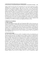
34.3 Structural performance in fire
34.3.1 Strength of steel at elevated temperatures
Steel begins to lose strength at about 200°C and continues to lose strength at an
increasing rate up to a temperature of about 750°C, when the rate of strength loss
flattens off. This relationship is shown in Fig. 34.3. An important parameter is the
strain at which the strength is assessed. It is reasonable to take a higher strain limit
than in normal design, because fire is an ultimate limit state and much higher deflec-
tions are allowed in fire tests than in normal structural tests.
1016 Fire protection and fire engineering
Fig. 34.3 Strength retention factor for grade 43 steel at elevated temperatures
Steel Designers' Manual - 6th Edition (2003)
This material is copyright - all rights reserved. Reproduced under licence from The Steel Construction Institute on 12/2/2007
To buy a hardcopy version of this document call 01344 872775 or go to
(a)
I
(b)
BS 5950 Part 8 specifies the use of 2.0% strain values for design of composite
beams and 1.5% strain for non-composite beams that are unprotected or protected
with ‘robust’ (i.e. deformable) fire protection materials. For columns and tensile
members or beams protected with ‘brittle’ material the use of 0.5% strain is speci-
fied for design calculations.
Design to Eurocode 3 (as proposed in the 2001 draft prEN 1993-1-2) is slightly
less conservative, with 2.0% strain being specified for beams and 1.0% when con-
sideration of deformation is required.
34.3.2 Performance of beams
Beams supporting concrete slabs behave better than uniformly heated sections, for
which the material performance is the dominant factor. The concrete slab causes
the top flange to be significantly cooler than the bottom flange and thus, as the
section is heated, the plastic neutral axis of the section rises towards the top flange
(see Fig. 34.4). The section resistance is determined by the strength of steel at 1.5%
strain, but in this case more of the web is effective in resisting tension.
The limiting temperatures of beams supporting concrete slabs are shown in Fig.
34.5 with the test results for a range of beam sizes and load ratios. These limiting
temperatures are increased by about 60°C relative to a uniformly heated section.
This temperature differential effect, and its beneficial influence on moving the
neutral axis, can be enhanced by partially or fully embedding steel beams into the
floors that they support.The shelf-angle beam and the Slimdek beam (shown in Fig.
34.6) are methods by which 30 minutes or 1 hour fire resistance can be achieved by
design, without the need for subsequent protection.
Structural performance in fire 1017
Fig. 34.4 Temperature and stress variation in I-beam supporting concrete slab when limit-
ing temperature is reached. (a) Section through beam and slab. (b) Temperature
variation. (c) Stress variation
Steel Designers' Manual - 6th Edition (2003)
This material is copyright - all rights reserved. Reproduced under licence from The Steel Construction Institute on 12/2/2007
To buy a hardcopy version of this document call 01344 872775 or go to