Volume 08 - Mechanical Testing and Evaluation Part 4 docx
Bạn đang xem bản rút gọn của tài liệu. Xem và tải ngay bản đầy đủ của tài liệu tại đây (6.31 MB, 150 trang )
number is based on the average of these two measurements. Table 5 provides a simple way to convert the
indentation diameter to the Brinell hardness number.
The indentations produced in Brinell hardness tests may exhibit different surface characteristics. In some
instances there is a ridge around the indentation that extends above the surface of the workpiece. In other
instances the edge of the indentation is below the original surface. Sometimes there is no difference at all. The
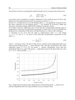
first phenomenon, called “ridging,” is illustrated in Fig. 13(a). The second phenomenon, called “sinking,” is
illustrated in Fig. 13(b). An example of no difference is shown in Fig. 13(c). Cold-worked metals and
decarburized steels are those most likely to exhibit ridging. Fully annealed metals and light case-hardened steels
more often show sinking around the indentation.
Fig. 13 Sectional views of Brinell indentations. (a) Ridging-type Brinell impression. (b) Sinking-type
Brinell impression. (c) Flat-type Brinell impression
The Brinell hardness number is related to the surface area of the indentation. This is obtained by measuring the
diameter of the indentation, based on the assumption that it is the diameter with which the indenter was in
actual contact. However, when either ridging or sinking is encountered there is always some doubt as to the
exact part of the visible indentation with which the actual contact was made. When ridging is present, the
apparent diameter of the indentation is greater than the true value, whereas the reverse is true when sinking
occurs.
Because of the above conditions, measurements of indentation diameters require experience and some judgment
on the part of the operator. Experience can be gained by measuring calibration indents in the standardized test
block.
Even when all precautions and limitations are observed, the Brinell indentations for some materials vary in
shape. For example, materials that have been subjected to unidirectional cold working often exhibit extreme
elliptical indentations. In such cases, where best possible accuracy is required, the indentation is measured in
four directions approximately 45° apart, and the average of these four readings is used to determine the Brinell
hardness number. Other techniques such as Rockwell-type depth measurements are often used with high-
production equipment.
Semiautomatic Indent Measurements. In an effort to reduce measurement errors, image analysis systems are
available for the measurement of the indent area. The systems normally consist of a solid-state camera mounted
on a flexible probe, which is typically manually placed over the indent (Fig. 14). A computer program then
analyzes the indent and calculates the size and Brinell number. The advantage of these systems is that they can
reduce the errors associated with the optical measurements done by an operator. The surface finish
requirements are frequently higher as the computer can have difficulty measuring noncircular indents or jagged
edges for which an experienced operator could make judgments and correct as needed.
Fig. 14 Computerized Brinell hardness testing optical scanning system
General Precautions and Limitations
To avoid misapplication and errors in Brinell hardness testing, the fundamentals and limitations of the test must
be thoroughly understood. The following precautions should be observed before testing.
Thickness of the testpiece should be such that no bulge or other marking showing the effect of the load appears
on the side of the piece opposite the impression. The thickness of the specimen should be at least ten times the
depth of the indentation. Depth of indentation may be calculated from the formula:
where P is load in kgf, D is ball diameter in mm, and HB is Brinell hardness number. For example, a reading of
300 HB indicates:
Therefore, the minimum thickness of the workpiece is 10 × 0.32 or 3.2 mm (0.125 in.). Table 8 gives minimum
thickness requirements.
Table 8 Minimum thickness requirements for Brinell hardness tests
Minimum thickness
of specimen
Minimum hardness for which the
Brinell test may be made safely
mm in. 3000 kgf load
1500 kgf load
500 kgf load
1.6 0.0625 602 301
100
3.2 0.125 301 150
50
4.8 0.1875 201 100
33
6.4 0.250 150 75
25
8.0 0.3125 120 60
20
9.6 0.375 100 50 17
Test surfaces that are flat give best results. Curved test surfaces of less than 25 mm (1 in.) radius should not be
tested.
Spacing of Indentations. For accurate results, indentations must not be made near the edge of the workpiece.
Lack of sufficient supporting material on one side will result in abnormally large, unsymmetrical indentations.
In most instances the error in Brinell hardness number will not be significant if the distance from the center of
the indentation to any edge of the workpiece is more than three times the diameter of the indentation.
Similarly, Brinell indentations must not be made too close to one another. The first indentation may cause cold
working of the surrounding area that could affect the subsequent test if made within this affected region. It is
generally agreed that the distance between centers of adjacent indentations should be at least three times the
diameter of the indentation to eliminate significant errors.
Anviling. The part must be anviled properly to minimize workpiece movement during the test and to position
the test surface perpendicular to the test force within 2°.
Surface Finish. The degree of accuracy attainable by the Brinell test can be greatly influenced by the surface
finish of the workpiece. The surface of the workpiece should be milled, ground, or polished so that the
indentation is defined clearly enough to permit accurate measurement. Care should be taken to avoid
overheating or cold working the surface, as that may affect the hardness of the material. In addition, for
accurate results, the workpiece surface must be representative of the material. Decarburization or any form of
surface hardening must be removed prior to testing.
Testing Machines
Various kinds of Brinell testers are available for laboratory, production, automatic, and portable testing. These
testers commonly use deadweight, hydraulic, pneumatic, elastic members (i.e., springs), or a closed-loop load-
cell system to apply the test loads. All testers must have a rigid frame to maintain the load and a means of
controlling the rate of load application to avoid errors due to impact (500 kgf/s maximum). The loads must be
consistently applied within 1.0% as indicated in ASTM E 10. In addition, the load must be applied so that the
direction of load is perpendicular to the workpiece surface within 2° for best results.
Bench units for laboratory testing are available with deadweight loading and/or pneumatic loading. Because of
their high degree of accuracy, deadweight testers are most commonly used in laboratories and shops that do
low- to medium-rate production. These units are constructed with weights connected mechanically to the
Brinell ball indenter. Minimum maintenance is required because there are few moving parts. Figure 15(a) is an
example of a motorized deadweight tester.
Fig. 15 Bench-type Brinell testers. (a) Motorized tester with deadweight loading. Courtesy of Wilson
Instruments. (b) Brinell tester with combined deadweight loading and pneumatic operation. Courtesy of
NewAge Industries
Bench units are also available with pneumatic load application or a combination of deadweight/pneumatic
loading. Figure 15(b) shows an example of the latter, where the load can be applied by release of deadweights
or by pneumatic actuation.
In both deadweight and pneumatic bench units, the testpiece is placed on the anvil, which is raised by an
elevating screw until the testpiece nearly touches the indenter ball. Operator controls initiate the load, which is
applied at a controlled rate and time duration by the test machine. The testpiece is then removed from the anvil,
and the indentation width is measured with a Brinell scope, typically at 20× power. Testing with this type of
apparatus is relatively slow and prone to operator influence on the test results.
Machines for Production Testing. Hydraulic testers were developed to reduce testing time and operator fatigue
in production operations. Advantages of hydraulic testers include operating economy, simplicity of controls,
and dependable accuracy. The controls prevent the operator from applying the load too quickly and thus
overloading. The load is applied by a hydraulic cylinder and monitored by a pressure gage. Normally the
pressure can be adjusted to apply any load between 500 and 3000 kgf. Hydraulic machines for production are
available as bench-top or floor units (Fig. 16).
Fig. 16 Hydraulic Brinell tester. Courtesy of Wilson Instruments
Automatic Testers. Many types of automatic Brinell testers are currently available. Most of these testers (such
as the one shown in Fig. 17) use a depth-measurement system to eliminate the time-consuming and operator-
biased measurement of the diameters. All of these testers use a preliminary load (similar to the Rockwell
principle) in conjunction with the standard Brinell loads. Simple versions of this technique provide only
comparative “go/no-go” hardness indications; more sophisticated models offer a microprocessor-controlled
digital readout to convert the depth measurement to Brinell numbers. Conversion from depth to diameter
frequently varies for different materials and may require correlation studies to establish the proper relationship.
Fig. 17 Automatic Brinell hardness tester with digital readout. Courtesy of NewAge Industries
These units can be fully automated to obtain production rates up to 600 tests per hour and can be incorporated
into in-line production equipment. The high-speed automatic testers typically comply with ASTM E 103,
“Standard Method of Rapid Indentation Hardness Testing of Metallic Materials.”
Portable Testing Machines. The use of conventional hardness testers may occasionally be limited because the
work must be brought to the machine and because the workpieces must be placed between the anvil and the
indenter. Portable Brinell testers that circumvent these limitations are available. A typical portable instrument is
shown in Fig. 18. This type of tester weighs only about 11.4 kg (25 lb), so it can be easily transported to the
workpieces. Portable testers can accommodate a wider variety of workpieces than can the stationary types. The
tester attaches to the workpiece as would a C-clamp with the anvil on one side of the workpiece and the
indenter on the other. For very large parts, an encircling chain is used to hold the tester in place as pressure is
applied.
Fig. 18 Hydraulic, manually operated portable Brinell hardness tester
Portable testers generally apply the load hydraulically, employing a spring-loaded relief valve. The load is
applied by operating the hydraulic pump until the relief valve opens momentarily. With this type of tester, the
hydraulic pressure should be applied three times when testing steel with a 3000 kgf load. This is equivalent to a
holding time of 15 s, as required by the more conventional method. For other materials and loads, comparison
tests should be made to determine the number of load applications required to give results equivalent to the
conventional method.
A comparison-type tester that uses a calibrated shear pin is shown in 19Fig. 19. In this method, a small pin of a
known shear load is placed in the indenter assembly against the indenter (Fig. 19b). Through hammer impact or
static clamping load, the indenter is forced into the material only as far is it takes to shear the pin. Excessive
force is absorbed after shear by upward movement of the indenter into an empty cavity. The resulting
impression is measured by the conventional Brinell method. This method does not comply with ASTM E 10.
Fig. 19 Pin Brinell hardness tester. (a) Clamp loading tester. (b) Schematic of pin Brinell principle
Equipment Maintenance. To maintain accurate results from Brinell testing, equipment must be calibrated and
serviced regularly, especially when machines are exposed to shop environments. The frequency of servicing
depends on whether the testers are used in a production line or for making an occasional test. However, it is
important that they be serviced and calibrated on a regular basis. Regular checking of the ball indenter for
deformation is particularly important. Indenters are susceptible to wear as well as to damage. When an indenter
becomes worn or damaged so that indentations no longer meet the standards, it must be replaced. Under no
circumstances should attempts be made to compensate for a worn or damaged indenter.
Verification of Loads, Indenters, and Microscopes. As with any procedure that is dependent on several
components, the accuracy of each must be verified to determine the accuracy of the result. In the case of Brinell
hardness testing, load, indenter, and microscope accuracies must lie within a specified tolerance to ensure
accurate results.
Load Verification. ASTM E 10 specifies that a Brinell hardness tester is acceptable for use over a load range
within which the load error does not exceed ±1%. Test loads should be checked by periodic calibration with a
proving ring or load cell, the accuracy of which is traceable to the National Institute of Standards and
Technology (NIST). Proving rings (see Fig. 20) are an elastic calibration device that is placed on the anvil of
the tester. The deflection of the ring under the applied load is measured either by a micrometer screw and a
vibrating reed or a reading dial gage. The amount of elastic deflection is then converted into load in kilograms
and compared with required accuracies.
Fig. 20 Proving rings used for calibrating Brinell hardness testers
Ball Indenter Verification. The ball indenter must be accurate within ±0.0005 mm of its nominal diameter. It is
very difficult for the user to measure the ball in enough locations to guarantee the correct shape. Therefore, a
close visual inspection is normally done, and any sign of damage will require replacement. A performance test
(indirect verification) using test blocks is the best way to verify the ball. When in doubt, the ball should be
replaced with a new ball certified by the manufacturer to meet all of the requirements in ASTM E 10.
Microscope Verification. The measuring microscope or other device used for measuring the diameter of the
impression should be verified at five intervals over the working range by the use of a scale of known accuracy
such as a stage micrometer. The adjustment of the micrometer microscope should be such that, throughout the
range covered, the difference between the scale divisions of the microscope and of the calibrating scale does not
exceed 0.01 mm.
Verification by Test Block (Indirect Verification). Standardized Brinell test blocks are available so that the
accuracy of the Brinell hardness tester can be indirectly verified at the hardness level of the work being tested.
Commonly available hardnesses are:
Test block material
Hardness, HB
Steel
500, 400, 350, 300, 250, 200
Brass
90
Aluminum 140
Good practice is to verify the tester throughout the hardness range encountered. This ensures that all test
parameters are within tolerance.
Application for Specific Materials
As is true for other indentation methods of testing hardness, the most accurate results are obtained when testing
homogeneous materials, regardless of the hardness range.
Steels. Virtually all hardened-and-tempered or annealed steels within the range of hardness mentioned provide
accurate results with the Brinell test. However,a s a rule, case-hardened steels are totally unsuitable for Brinell
testing. In most instances, the surface hardness is above the practical range and is rarely thick enough to provide
the required support for a Brinell test. Thus, “cave in” results, and grossly inaccurate readings are obtained.
Cast Irons. The large area of the test serves to average out the hardness difference between the iron and graphite
particles present in most cast iron. This averaging effect allows the Brinell test to serve as an excellent quality-
control tool.
Nonferrous metals (especially the wrought types) are generally amenable to Brinell testing, usually with the 500
kgf load, but occasionally with the 1500 kgf load. Some high-strength alloys such as titanium- and nickel-base
alloys that are phase-transformation- or age-hardened can utilize the 3000 kgf load. In this situation, practical
limits must be observed and some testing may be required to establish the optimal technique for testing a
specific metal or alloy.
There are certain multiphase cast nonferrous alloys that are simply too soft for accurate Brinell testing.
Microhardness testing is then employed. The lower limit of 16 HB with a 500 kgf load must always be
observed.
Powder Metallurgy Parts. Testing of P/M parts with a Brinell tester (or any sort of macro-hardness tester)
involves the same problem as encountered with cast iron. Instead of a soft graphite phase (some P/M parts also
contain free graphite), P/M parts contain voids that may vary widely in size and number. Light-load Brinell
testing is sometimes used successfully for testing of P/M parts, but its only real value is as a quality-control tool
in measuring the apparent hardness of P/M parts (see the article “Selection and Industrial Applications of
Hardness Tests” for more information on P/M hardness testing.)
Macroindentation Hardness Testing
Edward L. Tobolski, Wilson Instruments Division, Instron Corporation; Andrew Fee, Consultant
Vickers Hardness Testing
The Vickers hardness was first introduced in England in 1925 by R. Smith and G. Sandland (Ref 5). It was
originally known as the 136° diamond pyramid hardness test because of the shape of the indenter. The
manufacture of the first tester was a company known as Vickers-Armstrong Limited, of Crayford, Kent,
England. As the test and the tester gained popularity, the name Vickers became the recognized designation for
the test.
The Vickers test method is similar to the Brinell principle in that a defined shaped indenter is pressed into a
material, the indenting force is removed, the resulting indentation diagonals are measured, and the hardness
number is calculated by dividing the force by the surface area of the indentation. Vickers testing is divided into
two distinct types of hardness tests: macroindentation and microindentation tests. These two types of tests are
defined by the forces. Microindentation Vickers (ASTM E 384) is from 1 to 1000 gf and is covered in detail in
the article “Microindentation Hardness Testing.” this section focuses on the macroindentation range with test
forces from 1 to 120 kgf as defined in ASTM E 92. Selected international standards for Vickers hardness
testing are listed in Table 9.
Table 9 Selected Vickers hardness testing standards
Standard No.
Title
ASTM E 92
Standard Test Method for Vickers Hardness of Metallic Materials
BS EN ISO 6507-
1
Metallic Materials—Vickers Hardness Test—Part 1: Test Method
BS EN ISO 6507-
2
Metallic Materials—Vickers Hardness Test—Part 2: Verification of Testing
Machines
BS EN ISO 6507-
3
Metallic Materials—Vickers Hardness Test—Part 3: Calibration of Reference
Blocks
EN 23878
Hardmetals—Vickers Hardness Test
JIS B 7725
Vickers Hardness—Verification of Testing Machines
JIS B 7735
Vickers Hardness Test—Calibration of the Reference Blocks
JIS Z 2244
Vickers Hardness Test—Test Method
JIS Z 2252 Test Methods for Vickers Hardness at Elevated Temperatures
Test Method
As mentioned previously, the principle of the Vickers test is similar to the Brinell test, but the Vickers test is
performed with different forces and indenters. The square-base pyramidal diamond indenter is forced under a
predetermined load ranging from 1 to 120 kgf into the material to be tested. After the forces have reached a
static or equilibrium condition and further penetration ceases, the force remains applied for a specific time (10
to 15 s for normal test times) and is then removed. The resulting unrecovered indentation diagonals are
measured and averaged to give a value in millimeters. These length measurements are used to calculated the
Vickers hardness number (HV).
The Vickers hardness number (formerly known as DPH for diamond pyramid hardness) is a number related to
the applied force and the surface area of the measured unrecovered indentation produced by a square-base
pyramidal diamond indenter. The Vickers indenter has included face angles of 136° (Fig. 21), and the Vickers
hardness number (HV) is computer from the following equation:
where P is the indentation load in kgf, and d is the mean diagonal of indentation, in mm. This calculation of
Vickers hardness can be done directly from this formula or from Table 10 (lookup table in ASTM E 92). This
table contains calculated Vickers numbers for a 1 kgf load, so that it is not necessary to calculate every test
result. For example, if the average measured diagonal length, d, is 0.0753 mm with a 1 kgf load, then the
Vickers number is:
This value can be obtained directly from the lookup table. For obtaining hardness numbers when other loads are
used, simply multiply the number from the lookup table by the test load.
Table 10 Vickers hardness numbers
Diamond indenter, 136° face angle, load of 1 kgf
Vickers hardness number for diagonal measured to 0.0001 mm
Diagonal of
impression, nm
0.0000 0.0001 0.0002 0.0003 0.0004 0.0005 0.0006 0.0007 0.0008
0.0009
0.005 74,170 71,290 68,580 66,020 63,590 61,300 59,130 57,080 55,120
53,270
0.006 51,510 49,840 48,240 46,720 45,270 43,890 42,570 41,310 40,100
38,950
0.007 37,840 36,790 35,770 34,800 33,860 32,970 32,100 31,280 30,480
29,710
0.008 28,970 28,260 27,580 26,920 26,280 25,670 25,070 24,500 23,950
23,410
0.009 22,890 22,390 21,910 21,440 20,990 20,550 20,120 19,710 19,310
18,920
0.010 18,540 18,180 17,820 17,480 17,140 16,820 16,500 16,200 15,900
15,610
0.011 15,330 15,050 14,780 14,520 14,270 14,020 13,780 13,550 13,320
13,090
0.012 12,880 12,670 12,460 12,260 12,060 11,870 11,680 11,500 11,320
11,140
0.013 10,970 10,810 10,640 10,480 10,330 10,170 10,030 9,880 9,737
9,598
0.014 9,461 9,327 9,196 9,068 8,943 8,820 8,699 8,581 8,466
8,353
0.015 8,242 8,133 8,026 7,922 7,819 7,718 7,620 7,523 7,428
7,335
0.016 7,244 7,154 7,066 6,979 6,895 6,811 6,729 6,649 6,570
6,493
0.017 6,416 6,342 6,268 6,196 6,125 6,055 5,986 5,919 5,853
5,787
0.018 5,723 5,660 5,598 5,537 5,477 5,418 5,360 5,303 5,247
5,191
0.019 5,137 5,083 5,030 4,978 4,927 4,877 4,827 4,778 4,730
4,683
0.020 4,636 4,590 4,545 4,500 4,456 4,413 4,370 4,328 4,286
4,245
0.021 4,205 4,165 4,126 4,087 4,049 4,012 3,975 3,938 3,902
3,866
0.022 3,831 3,797 3,763 3,729 3,696 3,663 3,631 3,599 3,567
3,536
0.023 3,505 3,475 3,445 3,416 3,387 3,358 3,329 3,301 3,274
3,246
0.024 3,219 3,193 3,166 3,140 3,115 3,089 3,064 3,039 3,015
2,991
0.025 2,967 2,943 2,920 2,897 2,874 2,852 2,830 2,808 2,786
2,764
0.026 2,743 2,722 2,701 2,681 2,661 2,641 2,621 2,601 2,582
2,563
0.027 2,544 2,525 2,506 2,488 2,470 2,452 2,434 2,417 2,399
2,382
0.028 2,365 2,348 2,332 2,315 2,299 2,283 2,267 2,251 2,236
2,220
0.029 2,205 2,190 2,175 2,160 2,145 2,131 2,116 2,102 2,088
2,074
0.030 2,060 2,047 2,033 2,020 2,007 1,993 1,980 1,968 1,955
1,942
0.031 1,930 1,917 1,905 1,893 1,881 1,869 1,857 1,845 1,834
1,822
0.032 1,811 1,800 1,788 1,777 1,766 1,756 1,745 1,734 1,724
1,713
0.033 1,703 1,693 1,682 1,672 1,662 1,652 1,643 1,633 1,623
1,614
0.034 1,604 1,595 1,585 1,576 1,567 1,558 1,549 1,540 1,531
1,522
0.035 1,514 1,505 1,497 1,488 1,480 1,471 1,463 1,455 1,447
1,439
0.036 1,431 1,423 1,415 1,407 1,400 1,392 1,384 1,377 1,369
1,362
0.037 1,355 1,347 1,340 1,333 1,326 1,319 1,312 1,305 1,298
1,291
0.038 1,284 1,277 1,271 1,264 1,258 1,251 1,245 1,238 1,232
1,225
0.039 1,219 1,213 1,207 1,201 1,195 1,189 1,183 1,177 1,171
1,165
0.040 1,159 1,153 1,147 1,142 1,136 1,131 1,125 1,119 1,114
1,109
0.041 1,103 1,098 1,092 1,087 1,082 1,077 1,072 1,066 1,061
1,056
0.042 1,051 1,046 1,041 1,036 1,031 1,027 1,022 1,017 1,012
1,008
0.043 1,003 998 994 989 985 980 975 971 967
962
0.044 958 953 949 945 941 936 932 928 924
920
0.045 916 912 908 904 900 896 892 888 884
880
0.046 876 873 869 865 861 858 854 850 847
843
0.047 839 836 832 829 825 822 818 815 812
808
0.048 805 802 798 795 792 788 785 782 779
775
0.049 772 769 766 763 760 757 754 751 748
745
0.050 742 739 736 733 730 727 724 721 719
716
0.051 713 710 707 705 702 699 696 694 691
688
0.052 686 683 681 678 675 673 670 668 665
663
0.053 660 658 655 653 650 648 645 643 641
638
0.054 636 634 631 629 627 624 622 620 617
615
0.055 613 611 609 606 604 602 600 598 596
593
0.056 591 589 587 585 583 581 579 577 575
573
0.057 571 569 567 565 563 561 559 557 555
553
0.058 551 549 547 546 544 542 540 538 536
535
0.059 533 531 529 527 526 524 522 520 519
516.8
0.060 515.1 513.4 511.7 510.0 508.3 506.6 505.0 503.0 501.6
500.0
0.061 498.4 496.7 495.1 493.5 491.9 490.3 488.7 487.1 485.5
484.0
0.062 482.4 480.9 479.3 477.8 476.2 474.7 473.2 471.7 470.2
468.7
0.063 467.2 465.7 464.3 462.8 461.3 459.9 458.4 457.0 455.6
454.1
0.064 452.7 451.3 449.9 448.5 447.1 445.7 444.4 443.0 441.6
440.3
0.065 438.9 437.6 436.2 434.9 433.6 432.2 430.9 429.6 428.3
427.0
0.066 425.7 424.4 423.1 421.9 420.6 419.3 418.1 416.8 415.6
414.3
0.067 413.1 411.9 410.6 409.4 408.2 407.0 405.8 404.6 403.4
402.2
0.068 401.0 399.9 398.7 397.5 396.6 395.2 394.0 392.9 391.8
390.6
0.069 389.5 388.4 387.2 386.1 385.0 383.9 382.8 381.7 380.6
379.5
0.070 378.4 377.4 376.3 375.2 374.2 373.1 372.0 371.0 369.9
368.9
0.071 367.9 366.8 365.8 364.8 363.7 362.7 361.7 360.7 359.7
358.7
0.071 367.9 366.8 365.8 364.8 363.7 362.7 361.7 360.7 359.7
358.7
0.072 357.7 356.7 355.7 354.7 353.8 352.8 351.8 350.9 349.9
348.9
0.073 348,0 347.0 346.1 345.1 344.2 343.3 342.3 341.4 340.5
339.6
0.074 338.6 337.7 336.8 335.9 335.0 334.1 333.2 332.3 331.4
330.5
0.075 329.7 328.8 327.9 327.0 326.2 325.3 324.5 323.6 322.7
321.9
0.076 321.0 320.2 319.4 318.5 317.7 316.9 316.0 315.2 314.4
313.6
0.077 312.8 312.0 311.1 310.3 309.5 308.7 307.9 307.2 306.4
305.6
0.078 304.8 304.0 303.2 302.5 301.7 300.9 300.2 299.4 298.6
297.9
0.079 297.1 296.4 295.6 294.9 294.1 293.4 292.7 291.9 291.2
290.5
0.080 289.7 289.0 288.3 287.6 286.9 286.2 285.4 284.7 284.0
283.3
0.081 282.6 281.9 281.2 280.6 279.9 279.2 278.5 277.8 277.1
276.5
0.082 275.8 275.1 274.4 273.8 273.1 272.4 271.8 271.1 270.5
269.8
0.083 269.2 268.5 267.9 267.2 266.6 266.0 265.3 264.7 264.1
263.4
0.084 262.8 262.2 261.6 260.9 260.3 259.7 259.1 258.5 257.9
257.3
0.085 256.7 256.1 255.5 254.9 254.3 253.7 253.1 252.5 251.9
251.3
0.086 250.7 250.1 249.6 249.0 248.4 247.8 247.3 246.7 246.1
245.6
0.087 245.0 244.4 243.9 243.3 242.8 242.2 241.6 241.1 240.6
240.0
0.088 239.5 238.9 238.4 237.8 237.3 236.8 236.2 235.7 235.2
234.6
0.089 234.1 233.6 233.1 232.5 232.0 231.5 231.0 230.5 230.0
229.4
0.090 228.9 228.4 227.9 227.4 226.9 226.4 225.9 225.4 224.9
224.4
0.091 223.9 223.4 222.9 222.5 222.0 221.5 221.0 220.5 220.0
219.6
0.092 219.1 218.6 218.1 217.7 217.1 216.7 216.3 215.8 215.3
214.9
0.093 214.4 213.9 213.5 213.0 212.6 212.1 211.7 211.2 210.8
210.3
0.094 209.9 209.4 209.0 208.5 208.1 207.6 207.2 206.8 206.3
205.9
0.095 205.5 205.0 204.6 204.2 203.8 203.3 202.9 202.5 202.1
201.6
0.096 201.2 200.8 200.4 200.0 199.5 199.1 198.7 198.3 197.9
197.5
0.097 197.1 196.7 196.3 195.9 195.5 195.1 194.7 194.3 193.9
193.5
0.098 193.1 192.7 192.3 191.9 191.5 191.1 190.7 190.4 190.0
189.6
0.099 189.2 188.8 188.4 188.1 187.7 187.3 186.9 186.6 186.2 185.5
Source: ASTM E 92
Fig. 21 Diamond pyramid indenter used for the Vickers test and resulting indentation in the workpiece.
d, mean diagonal of the indentation in millimeters
Quite often the length of indentations are larger than the values given in most lookup tables. Calculation of
larger indentations is best shown by the following example: with a test load of 50 kgf, the averaged diagonal
length is measured at 0.753 mm. This length is beyond the range of the lookup table; however, the table can be
extended by looking up the hardness number for a 0.0753 mm indent diagonal, which has a Vickers hardness of
327 for a 1 kgf load (Table 10). Therefore, for a 0.753 mm diagonal, the table (if extended) would read 3.27 HV
at 1 kgf. With a 50 kgf load, then:
HV = 3.27 × 50 = 163.5
The Vickers hardness number is followed by the symbol “HV” with a suffix number denoting the force and a
second suffix number indicating the dwell time, if different from 10 to 15 s, which is normal dwell time. For
example:
6. A value of 440 HV30 represents Vickers hardness of 440 made with a force of 30 kgf applied for 10 to
15 s.
7. 440 HV30/20 represents Vickers hardness of 440 made with a force of 30 kgf applied for 20 s.
Macroindentation Vickers Test Loads. The forces of 5, 10, 20, 30, 50, 100, and 120 kgf are the most commonly
used in industry today for Vickers macroindentation hardness testing. The 30 kgf force seems to be the most
desirable and is used for most standardizing and calibration work. This is not to imply that the other forces
cannot be used for calibrating the testers by the indirect or test block method. The applied forces normally are
checked by using a calibrated electronic load cell. A Vickers hardness tester should be verified at a minimum of
three forces including the forces specified for testing. The tester is considered force calibrated if the error is not
greater than 1%. These forces should be applied in a smooth and gradual manner so that impact or overloading
is avoided. The loading should be such that it does not cause any movement of the specimen while under test.
The Vickers indenter is a highly polished, pointed square-base pyramidal diamond (Fig. 21) with opposite face
angles of 136 ± 5° that produces edge angles of 148° 06′ 43″. All four faces are equally inclined to the vertical
axis of the indenter to within ±30′ and meet at a common point so as not to produce an offset greater than 0.001
mm in length. The indenter should be periodically examined by making an indentation in a polished steel block
and observing the indent formed under high magnification (500×). The indentation edges and point should be
examined for rounding and chipping or other damage to the diamond. A wider and brighter image at the point
or diagonal edges will indicate excessive wear. If chipping occurs, it will be indicated by a bright spot that
usually occurs on the angle edges (diagonals). Any noticeable damage or wear would indicate that the indenter
should be replaced.
The measuring microscope or measuring device must be capable of determining the length of the indentation
diagonals to ±0.0005 mm (0.5 μm) or ±0.5% of length, whichever is larger, in accordance to ASTM E 92,
“Standard Test Method for Vickers Hardness of Metallic Materials.” The most common measuring system is
either a basic vertical light microscope or an optical projection screen (Fig. 22). The magnification range is
usually from 4 to 500×, depending on the size of the indentation to be measured. The optical measuring device
generally uses a Filar micrometer eyepiece, a graduated incremental scale, or a sliding vernier attachment. The
measuring microscope or other device for measuring the diagonals of the indentation is calibrated with a
precision stage micrometer. As per ASTM E 92 the error of the spacing of the lines of the stage micrometer
shall not exceed 0.05 μm or 0.05% of any interval. The measuring device is calibrated throughout its range of
use, and a calibration factor is utilized so that an error shall not exceed ±0.5%.
Fig. 22 Optical projection screen and caliper for diagonal measurement in Vickers hardness testing
Determining the calibration factor is critical for accurate diagonal measurements and should be done with care
and precision. Multiple verifications should be made at several micron lengths representing the full range of
measurements normally used. The averaged values should be used to calculate the calibration factor.
Video Measuring Systems and Image Processors. Newer measurement techniques successfully use image
processing and analysis. This technique utilizes a scanning device, usually a microscope equipped with a solid-
state video camera with a photodiode array lens that is sensitized to gray shading of the field of view. The
digital image is sent to a computer that processes the photo-array output and sends a signal that projects an
image on a television screen. This technique, due to the limitations of the pixel arrays in the cameras, does not
have the accuracy of a trained operator using a high-quality conventional microscope. However, the method can
improve the level of repeatability, especially when multiple operators are involved. The accuracy is being
improved as the pixel arrays are reduced in size; however, measurements below 0.05μm are not possible with
existing equipment. Another use of a solid-state video camera is commonly called a video Filar, or Vilar,
system (Fig. 23). With this type of system the operator still has to locate the indent diagonals using a joystick or
mouse; however, observing the image on the television screen is easier and less tiring than a microscope,
resulting in more consistent results.
Fig. 23 Vilar system for digital image processing of Vickers indents
Application Factors
Test Specimen. The Vickers hardness test is adaptable to most test specimens ranging from large bars and
rolled stock to small pieces in metallographic mounts. The surface should be flat, polished, and supported
rigidly normal to the axis of the indenter. The distance from the center of the indentation to other indents or
from the specimen edge should be at least 2.5 times the diagonal length. The thickness of the test specimen
should be such that no bulge or marking appear on the underside surface directly opposite the indentation, and
it is recommended that the thickness of the testpiece be equal to 1.5 times the length of the diagonal of the
indentation. As the depth of the Vickers test is approximately
1
7
of the diagonal, the rule of thumb is that the
thickness of the testpiece should be 10 times the depth of the indentation.
The finish of the specimen must be smooth enough to permit the ends of the diagonals to be clearly defined so
the length can be measured with a precision of 0.0005 mm or 0.5% of the length of the diagonals, whichever is
larger. It is necessary that sample preparation be carefully controlled to ensure that changes to the hardness of
the material are avoided. The test surface of the specimen should be presented normal to the axis of the indenter
within ±1°.
Testing of Cylindrical and Spherical Rounds. When testing specimens with radius of curvature, a factor is
required to correct the readings as though the testing was done on a flat surface. A method for correcting
Vickers hardness values taken on spherical and cylindrical surfaces has been standardized as ISO 6507-1. The
correction factors are tabulated in terms of the ratio of the mean diagonal d of the indentation to the diameter D
of the sphere or cylinder. Tables listing correction factors for convex and concave spherical surfaces and for
cylindrical surfaces are provided in the article “Selection and Industrial Applications of Hardness Tests” in this
Volume.
The rationale for this manner of correcting Vickers values on spheres and cylinders is that when testing a
convex cylinder the indentation will have shorter diagonals in the curve region (90° to the longitudinal axis)
compared to diagonals parallel to the long axis. This results in a shorter mean diagonal length (and a higher
hardness number) than if tested on a flat surface. The correction for a convex surface therefore must be less
than 1.0 to reduce the higher hardness value caused by the convex surface. The reverse is true for concave radii;
the correction ratios are greater than 1.0, which increases the hardness value. The corrections for similar d/D
ratios are the largest for the spherical surfaces.
Following is an example of hardness correction for a spherical surface. Similar examples for cylindrical
surfaces are given in the article “Selection and Industrial Applications of Hardness Tests” in this Volume. For
cylinders, correction factors depend on whether the diagonal is parallel or perpendicular to the longitudinal axis
of the cylinder. In general, correction factors for cylinders are smallest when the measured diagonal is parallel
to the longitudinal axis of a cylinder.
Example 1: Hardness Correction for a Convex Sphere. The test conditions are:
Force, kgf
10
Diameter of sphere (D), mm
10
Mean diagonal of indentation (d), mm
0.150
d/D 0.150/10 = 0.015
From the Vickers hardness table (Table 10) and adjusted for 10 kgf load, hardness for a flat surface would be
824 HV10. From the correction table (see Table 5 in the article “Selection and Industrial Application of
Hardness Tests” in this Volume), the correction factor (by interpolation) is 0.983. Thus, the corrected hardness
of the sphere is 824 × 0.983 = 810 HV 10.
Advantages and Disadvantages. One advantage of the Vickers test is that in theory constant hardness values can
be obtained from homogeneous material irrespective of the test force. This generally works for force levels
above 5 kg. The other advantage is that one hardness scale can be used from the softest to the hardest metals
including carbides. As a result of these advantages and the relative simplicity of the test process, the Vickers
scale may be useful for maintaining stable hardness standards.
In summary, advantages of the Vickers test are:
8. Vickers hardness, in general, is independent of force when determined on homogeneous material, except
possibly at forces below 5 kgf.
9. The edge or ends of the diagonals are usually well defined for measurement.
10. The indentations are geometrically similar, irrespective of size.
11. One continuous scale is used for a given force, from lowest to highest values.
12. Indenter deformation is negligible on hard material.
Disadvantages of the Vickers test are:
13. Test is slow and not well adapted for routine testing. Typical test and measurement times are in the one-
minute range.
14. Careful surface preparation of the specimen is necessary, especially for shallow indentations.
15. Measurement of diagonals is operator dependent, with possible eyestrain and fatigue adding to test
errors.
Comparison with Brinell Testing. Because of the geometric similarity of the indentations, Vickers hardness
values are independent of the applied force. That is to say that on homogeneous material the hardness value
obtained with a 10 kgf load should be the same as that obtained with a 50 kgf load. When the Vickers test was
first introduced, Vickers hardness values were practically constant under different forces for different materials,
whereas values from Brinell testing were not. The angle of 136° was chosen by Smith and Sandland (Ref 5) to
represent the most desirable ratio of indentation diameter to the ball diameter in the Brinell test.
Due to the fact that the Brinell test does not always yield constant hardness values with varying forces, and in
order to minimize this variable, it is generally advisable to restrict the indentations to 25 to 50% of the diameter
of the ball. Therefore the ideal size of the ball indentation lies midway between these ratios or at 0.375D. This
was the reasoning of Smith and Sandland so that some method of comparison between their test and Brinell
testing could be done. The tangential angle of indentation corresponding with 0.375 times the ball diameter is
136°.
Studies have shown that hardness values obtained with Vickers testing are almost identical to those done with
the Brinell test when the force has been such to produce an indentation in the range of 0.375 times the ball
diameter. This similarity only holds true in the softer hardness ranges from approximately 100 to 300 HB. At
approximately 350 HB the Brinell test has a slight tendency to yield lower readings than does the Vickers test,
and this tendency becomes more pronounced as the hardness increases. It should be noted that some studies
have indicated a decrease in hardness values as the forces are increased when testing mild steels and soft
coppers.
Effect of Elastic Recovery. As noted in the article “Selection and Industrial Applications of Hardness Tests,”
the elastic response of a material can cause a change in the indent shape after unloading. A perfect pyramid
indentation (area A
2
in Fig. 24) does not always remain after unloading. This is caused by “ridging” and
“sinking” at the surface of the material being tested. Ridging during Vickers does not occur in a concentric
ridge, as found in the Brinell test, but rather the material extrudes upward along the face of the diamond leaving
the material at the corners of the indentation near the original level. This bulging effect on the sides of the
indentation (A
3
in Fig. 24) is called “convexity” and indicates the material has been cold worked. Indents with a
sinking-in appearance (A
1
in Fig. 24) show a downward curvature of the material along the face of the diamond
called “concavity.”
Fig. 24 Vickers indentations with equal diameters but different areas
Because Vickers hardness is related to the surface area of the indentation, these effects influence hardness
readings. When ridging occurs, the diagonal measurement gives a low value for the true contact area and
therefore a higher hardness value (A
2
< A
3
in Fig. 24). The exact opposite occurs with the sinking type and
causes high values of the area and low hardness numbers (A
1
< A
2
in Fig. 24). It has been shown that errors as
high as 10% in hardness numbers using the conventional formula may occur on different metals due to these
effects. Generally, cold-worked alloys and decarburized steels will demonstrate the ridging type, while
annealed and softer metals are prone to the sinking type.
Anisotropy. When testing anisotropic or heavily rolled materials, it is recommended that the test specimen be
oriented to have both diagonals approximately the same length. This would necessitate reorienting the testpiece
so that its direction of rolling is at a 45° angle to the diagonals direction, thus equalizing the lengths. Distortion
of the indentation, due to crystallographic or microstructural texture, influences diagonal lengths and the
validity of the hardness value. A Vickers indentation that has one-half of either diagonal 5% longer than the
other half of the diagonal will produce an error of approximately 2.5% in hardness values. Therefore it is
recommended, whenever possible, that only symmetrical indentations be used to obtain hardness values.
If the diagonal legs are unequal, the specimen should be rotated 90° and another indent made. If the
nonsymmetrical aspect of the indent has rotated, this indicates that the specimen surface is not perpendicular to
the indenter axis. If the nonsymmetrical nature remains in the same orientation, the indenter is misaligned or
damaged.
Vickers testers should be designed to apply the force smoothly and friction free without impact. The error of the
indenting force must not exceed 1%, and the measuring device shall be capable of measuring accuracies within
±0.0005 mm or ±0.5%, whichever is larger. Many of the testers available today apply force by means of
deadweights and lever combinations, usually with a dashpot control to impede overshoot.
Recently, motorized closed-loop, load-cell force application testers (Fig. 25) have been developed. They have
the advantage of allowing a nearly limitless selection of test forces. Manual measuring devices that require
operator calculation of the Vickers number are still produced; however, most testers have full digital systems
that automatically do the calculations. Digital testers also have the ability to download test results to a printer or
host computer.
Fig. 25 Closed-loop servo controlled Vickers hardness testing unit
Calibrations. Vickers testers are typically indirectly verified for performance by doing periodic tests on certified
test blocks. A wide variety of test blocks are available in different hardness ranges calibrated with different test
forces. It is recommended that each test force used be verified using at least two test blocks of different
hardnesses.
Reference cited in this section
16. R.L. Smith and G.E. Sandland, Some Notes on the Use of a Diamond Pyramid for Hardness Testing, J.
Iron Steel Inst. (London), 1925
Macroindentation Hardness Testing
Edward L. Tobolski, Wilson Instruments Division, Instron Corporation; Andrew Fee, Consultant
References
17. F. Garofalo, P.R. Malenock, and G.V. Smith, Hardness of Various Steels at Elevated Temperatures,
Trans. ASM, Vol 45, 1953, p 377–396
18. M. Semchyshen and C.S. Torgerson, Apparatus for Determining the Hardness of Metals at
Temperatures up to 3000 °F, Trans. ASM, Vol 50, 1958, p 830–837
19. J.H. Westbrook, Temperature Dependence of the Hardness of Pure Metals, Trans. ASM, Vol 45, 1953, p
221–248
20. L. Small, “Hardness—Theory and Practice,” Service Diamond Tool Company, Ferndale, MI, 1960, p
363–390
21. R.L. Smith and G.E. Sandland, Some Notes on the Use of a Diamond Pyramid for Hardness Testing, J.
Iron Steel Inst. (London), 1925
Microindentation Hardness Testing
George F. Vander Voort, Buehler Ltd.
Introduction
IN MICROINDENTATION HARDNESS TESTING (MHT), a diamond indenter of specific geometry is
impressed into the surface of the test specimen using a known applied force (commonly called a “load” or “test
load”) of 1 to 1000 gf. Historically, the term “microhardness” has been used to describe such tests. This term,
taken at face value, suggests that measurements of very low hardness values are being made, rather than
measurements of very small indents. Although the term “microhardness” is well established and is generally
interpreted properly by test users, it is best to use the more correct term, microindentation hardness testing.
There is some disagreement over the applied force range for MHT. ASTM E 384 states that the range is 1 to
1000 gf, and this is the commonly accepted range in the United States. Europeans tend to call the range of 200
to 3000 gf the “low-load” range. They do this because forces smaller than 200 gf generally produce hardness
numbers that are different from those determined from tests conducted with forces ≥200 gf. This problem is
discussed later in this article.
The hardness number is based on measurements made of the indent formed in the surface of the test specimen.
It is assumed that recovery does not occur upon removal of the test force and indenter, but this is rarely the
case. The Knoop test is claimed to eliminate recovery, but again, this is not true for tests of metallic materials.
For the Vickers test, both diagonals are measured and the average value is used to compute the Vickers
hardness (HV). The hardness number is actually based on the surface area of the indent itself divided by the
applied force, giving hardness units of kgf/mm
2
. In the Knoop test, only the long diagonal is measured, and the
Knoop hardness (HK) is calculated based on the projected area of the indent divided by the applied force, also
giving test units of kgf/mm
2
. In practice, the test units kgf/mm
2
(or gf/μm
2
) are not reported with the hardness
value.
Microindentation Hardness Testing
George F. Vander Voort, Buehler Ltd.
Vickers Hardness Test
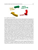
In 1925, Smith and Sandland of the United Kingdom developed an indentation test that employs a square-based
pyramidal-shaped indenter made from diamond (Fig. 1a). Figure 1(b) shows examples of Vickers indents to
illustrate the influence of test force on indent size. The test was developed because the Brinell test, using a
spherical hardened steel indenter, could not test hard steels. They chose the pyramidal shape with an angle of
136° between opposite faces in order to obtain hardness numbers that would be as close as possible to Brinell
hardness numbers for the same specimens. This made the Vickers test easy to adopt, and it rapidly gained
acceptance. Unlike Rockwell tests, the Vickers test has the great advantage of using one hardness scale to test
all materials.
Fig. 1 Vickers hardness test. (a) Schematic of the square-based diamond pyramidal indenter used for the
Vickers test and an example of the indentation it produces. (b) Vickers indents made in ferrite in a
ferritic-martensitic high-carbon version of 430 stainless steel using (left to right) 500, 300, 100, 50, and 10
gf test forces (differential interference contrast illumination, aqueous 60% nitric acid, 1.5 V dc). 250×
In this test, the force is applied smoothly, without impact, and held in contact for 10 to 15 s. The force must be
known precisely (refer to ASTM E 384 for tolerances). After the force is removed, both diagonals are measured
and the average is used to calculate the HV according to:
(Eq 1)
where d is the mean diagonal in μm, P is the applied load in gf, and α is the face angle (136°).
The hardness can be computed with the formula and a pocket calculator, or using a spreadsheet program. Most
modern MHT units have the calculation capability built in and display the hardness value along with the
measured diagonals. A book of tables of HV as a function of d and P also accompanies most testers, and ASTM
E 384 includes such tables.
The macro-Vickers test (ASTM E 92) operates over a range of applied forces from 1 to 120 kgf, although many
testers cover a range of only 1 to 50 kgf, which is usually adequate. The use of forces below 1 kgf with the
Vickers test was first evaluated in 1932 at the National Physical Laboratory in the United Kingdom. Four years
later, Lips and Sack constructed the first Vickers tester designed for low applied forces.
Microindentation Hardness Testing
George F. Vander Voort, Buehler Ltd.
Knoop Hardness Test
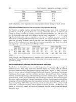
In 1939, Frederick Knoop and his associates at the former National Bureau of Standards developed an alternate
indenter based on a rhombohedral-shaped diamond with the long diagonal approximately seven times as long as
the short diagonal (Fig. 2a). Figure 2(b) shows examples of Knoop indents to illustrate the influence of applied
load on indent size. The Knoop indenter is used in the same machine as the Vickers indenter, and the test is
conducted in exactly the same manner, except that the Knoop hardness (HK) is calculated based on the
measurement of the long diagonal only and calculation of the projected area of the indent rather than the surface
area of the indent:
(Eq 2)
where C
p
is the indenter constant, which permits calculation of the projected area of the indent from the long
diagonal squared.
Fig. 2 Knoop hardness test. (a) Schematic of the rhombohedral-shaped diamond indenter used for the
Knoop test and an example of the indentation it produces. (b) Knoop indents made in ferrite in a ferritic-
martensitic high-carbon version of 430 stainless steel using (left to right) 500, 300, 100, 50, and 10 gf test
forces (differential interference contrast illumination, aqueous 60% nitric acid, 1.5 V dc). 300×
The Knoop indenter has a polished rhombohedral shape with an included longitudinal angle of 172° 30′ and an
included transverse angle of 130° 0′. The narrowness of the indenter makes it ideal for testing specimens with
steep hardness gradients. In such specimens, it may be impossible to get valid Vickers indents as the change in
hardness may produce a substantial difference in length of the two halves of the indent parallel to the hardness
gradient. With the Knoop test, the long diagonal is set perpendicular to the hardness gradient and the short
diagonal is in the direction of the hardness gradient.
For the same test force, Knoop indents can be more closely spaced than Vickers indents, making hardness
traverses easier to perform. The Knoop indenter is a better choice for hard brittle materials where indentation
cracking would be more extensive using the Vickers indenter at the same load. The Knoop indent is shallower
(depth is approximately the long diagonal) than the Vickers indent (depth is approximately the average
diagonal). Hence, the Knoop test is better suited for testing thin coatings. On the negative side, the Knoop
hardness varies with test load and results are more difficult to convert to other test scales.
Microindentation Hardness Testing
George F. Vander Voort, Buehler Ltd.
Expression of Test Results
Historically, the official way in which Vickers and Knoop hardness numbers have been presented has varied
with time, although many users seem to be unaware of the preferred style. The acronyms VHN and KHN were
introduced many years ago and stand for Vickers hardness number and Knoop hardness number. DPN, for
diamond-pyramid hardness number, was introduced at approximately the same time. While some have claimed
the DPN and VHN are not the same, this is not true. In the early 1960s, ASTM initiated a more modern,
systematic approach for all hardness tests and adopted the acronyms HV and HK for the two tests, yet the
former acronyms are still widely used (as are many other obsolete acronyms, like BHN and R
C
instead of HB
and HRC). Style guides for many publications do not seem to track these changes carefully.
For stating the actual hardness results, ASTM advocates the following approach. ASTM E 384 recommends
expressing a mean hardness of 425 in the Vickers test using a 100 gf applied force as 425 HV
100
, while by ISO
rules, it would be expressed as 425 HV
0.1
(because 100 gf would be expressed as 0.1 kgf). ASTM Committee E-
4 is currently recommending adoption of a slightly different approach: 425 HV 100 gf. While it has proven
difficult to get people to adopt a unified expression style, it is important that the stated results indicate the mean
value, the test used, and the test force as a minimum.
Microindentation Hardness Testing
George F. Vander Voort, Buehler Ltd.
Microindentation Hardness-Testing Equipment
A variety of microindentation test machines are produced, ranging from relatively simple, low-priced units
(Fig. 3) to semiautomated systems (Fig. 4a) and fully automated systems (Fig. 4b). In most cases, either a
Knoop or a Vickers indenter can be used with the same machine, and it is a relatively simple matter to
exchange indenters. The force is applied either directly as a dead weight or indirectly by a lever and lighter
weights. New testers using a closed-loop load-cell system (Fig. 5) are also available. The magnitude of the
weights and force application must be controlled precisely (refer to ASTM E 384).
Fig. 3 Example of a simple, low-cost manual microindentation hardness-testing unit with a Filar
micrometer for measurements but no automation
Fig. 4 Semiautomated and fully automated microindentation hardness testers. (a) Semiautomated tester
with a Filar micrometer for measurements, automated readout of the test results with its equivalent
hardness in another selected scale. (b) Fully automated tester interfaced to an image analyzer to control
indenting, measurement, and data manipulation
Fig. 5 Closed-loop load-cell microindentation hardness tester
Most tester systems use an automated test cycle of loading, applying the load for the desired time, and
unloading to ensure reproducibility in the test. Vibrations must be carefully controlled, and this becomes even
more important as the applied force decreases. Manual application and removal of the applied force is not
recommended due to the difficulty in preventing vibrations that will enlarge the indent size.
The indenter must be perpendicular to the test piece. An error of as little as 2° from perpendicular will distort
the indentation shape and introduce errors. A larger tilt angle may cause the specimen to move under the
applied force. To aid in controlling this problem, most testers come with a device that can be firmly attached to
the stage (Fig. 6). The mounted specimen, or a bulk unmounted specimen of the proper size, can be placed
within this device and the plane-of-polish is automatically indexed perpendicularly to the indenter. Historically,
it has been a common practice to simply place a specimen on the stage and proceed with indentation, but if the
plane-of-polish is not parallel to the back side of the specimen, it will not be perpendicular to the indenter,
introducing tilt errors.
Fig. 6 Examples of fixtures for holding test pieces for microindentation hardness testing
The stage is an important part of the tester. The stage must be movable and movement is usually controlled in
the x and y directions by micrometers. Once the specimen is placed in the top-indexed holder, the operator must
move the stage micrometers to select the desired location for indenting. If a traverse of several hardness
readings is desired at inward intervals from a side surface of the specimen (as in case-depth measurements),
then the surface of interest should be oriented in the holder so that it is perpendicular to either the x or y
direction of the traverse. If the Knoop indenter is chosen, its long diagonal must also be parallel to the surface
of interest. For example, if the Knoop long axis is in the direction going from the front to the back of the tester,
then the surface of interest must also be aligned in the same direction. Accordingly, the x-axis (left to right)
micrometer is used to select the desired indentation positions. The micrometers are ruled in either inches or
millimeters and are capable of making very precise movement control.
Because the diagonals must be measured after the force has been removed, the tester is equipped with at least
two metallurgical objectives (i.e., reflected light), usually 10× and 40×. Some systems may have a third or
fourth objective on the turret. For measurement of small indents (<20 μm in diagonal length), a higher-power
objective (60×, 80×, or 100×) can be used in place of the 40× objective if the tester has places for only two
objectives. The objectives should have a reasonably high numerical aperture for their magnifications to give the
best resolution. The 10× objective is usually used as a spotter, that is, simply to find the desired test location.
The measuring eyepiece is generally 10×. Naturally, the optical system must be carefully calibrated using a
stage micrometer. In general, indents are measured to the nearest 0.1 μm with an accuracy of no more than ±0.5
μm in length. A proper Köhler illumination system is necessary to fully illuminate the specimen. In general, a
magnification that makes the diagonal between 25% and less than 75% of the field width is ideal; however, it is
not always possible to follow this rule.
Calculation of the hardness is based on the length of the diagonals. The major problem is defining where the
indent tips are located. This requires proper illumination, adjustment of the optics for best resolution and
contrast, and careful focusing. Every laboratory should have a regular schedule for cleaning the optical
components of their MHT apparatuses, as well as for verifying their calibration. A Filar micrometer is used for
the diagonal measurement. The micrometer lines have a finite thickness, which requires use of a systematic
measurement scheme. Several indent measurement approaches can be used. One popular approach is to bring
the two Filar lines just into contact and then zero the micrometer. The interior sides of the Filar lines are then
adjusted so that the indent tips just touch the inside of each line.
In recent years, the MHT system has been automated by coupling it to an image analyzer (Fig. 4b). The image-
analysis system software is used to control all of the functions regarding indent location, indent spacing,
number of indents, indenting, measurement of the indents, calculation of hardness values, and data plotting. For
those who perform a substantial number of hardness traverses, this equipment is very useful because the test
work is automated, allowing the metallographer to do other tasks.
Microindentation Hardness Testing
George F. Vander Voort, Buehler Ltd.
Hardness Conversions
Sometimes it is desirable to know the equivalent hardness in a scale other than the Vickers or Knoop. It is not
uncommon for product specifications to define the hardness for a case depth in the Rockwell C scale, which, of
course, is a bulk test scale unsuitable for case depth determination. Although this seems (and is) illogical, it is
widely practiced, probably because designers are not familiar with the Vickers or Knoop scales. Hardness
conversions are developed empirically, and there is a degree of error associated with all conversions. The
primary source for hardness conversions is ASTM E 140, which lists the conversions in tabular form and also
contains equations based on the tabular data. Some MHT units have these tables or the equations built in and
will list an equivalent hardness of your choice with each measurement. The most common conversion is from a
Vickers or Knoop scale to a Rockwell C scale. In general, these conversions are most commonly available for
steels, aluminum alloys, and nickel alloys. Conversions between various scales may be material sensitive.
Conversion of Vickers data to other scales is more straightforward than converting Knoop data to other scales.
Basically, the ASTM E 140 conversions between Vickers and other scales can be used for any test force greater
than 100 gf. Conversions of Knoop to other scales are problematic because Knoop hardness varies more with
load. If the published conversion is for a 500 gf applied load, then this conversion is best for that load and
reasonably accurate for loads slightly lower and generally adequate for greater loads, as the Knoop hardness is
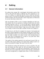
reasonably constant for loads of 500 gf and above. Aside from the E 140 conversions, two published conversion
charts are worth noting. First, Emond (Ref 1) published a correlation chart of Vickers hardness (10 kgf load) to
Knoop hardness at loads of 10, 25, 50, 100, 200, and 500 gf (Fig. 7). Second, Batchelder (Ref 2) published
conversions from Knoop hardness, with loads of 15, 25, 50, 100, 200, 300, 500, and 1000 gf, to Rockwell C
(Fig. 8). Before using these conversions, it is a good practice to test your material with both scales to see how
well the conversion chart agrees with your bulk test specimens before utilizing the conversions.