Volume 18 - Friction, Lubrication, and Wear Technology Part 6 pot
Bạn đang xem bản rút gọn của tài liệu. Xem và tải ngay bản đầy đủ của tài liệu tại đây (1.85 MB, 80 trang )
The cavitation erosion resistance of cobalt alloys is superior to that of the stainless steels, but their cost is considerably
higher. The economic factors, together with a better understanding of the factors responsible for the high erosion
resistance of the cobalt alloys, have simulated the recent development (Ref 12) of new cavitation-resistant iron-base
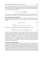
alloys. The success of this development is evidenced by the erosion data given in Fig. 4 for the new alloys designated
IRECA and several iron- and cobalt-base commercial alloys. More comparative data on the erosion rates of various
materials are given in the article "Liquid Impingement Erosion" in this Volume.
Fig. 4 Cavitation erosion weight loss as function of exposure time measured
on various standard and
experimental alloys in ASTM G 32 vibratory tests. Source: Ref 12
Surface Coatings and Treatments. The recent trend in materials development has been to specify a component for
bulk property requirements and subsequently coat or treat the surface to provide the required environmental resistance.
Welded overlays of stainless steels or cobalt alloys are commonly used to provide resistance to cavitation erosion. Several
alternative coating techniques that have been investigated in the laboratory in recent years include: arc-sprayed coatings
(Ref 24), plasma-sprayed coatings (Ref 25, 26), laser hardening, cladding and alloying (Ref 10, 27), ion implantation (Ref
28, 29), and electroless nickel coatings (Ref 30). Plasma-sprayed coatings and laser treatments are beginning to be applied
in practice for this purpose.
Of these techniques, plasma spraying (Ref 31) is probably the most commercially well developed and offers flexibility in
terms of the types of materials that can be sprayed. In addition, the technique can be carried out in air, in inert gas
atmospheres, or in a reduced-pressure environment.
There are two major disadvantages of plasma-sprayed coatings. One is that the coating is generally only mechanically
bonded to the substrate and therefore does not exhibit very good adhesion. The other disadvantage is the inherent porosity
of the coatings. One of the more erosion-resistant coatings produced by plasma spraying is of the "shape memory" alloy,
NiTi (Ref 24). Like cobalt and the IRECA stainless steel, NiTi owes its superior properties to a stress-induced phase
transformation.
Laser surface treatments appear to offer the most possibilities and advantages. By rapidly heating (but not melting) and
quenching the surface of a finished component, an extremely hard and resistant surface layer can be induced without
requiring any further surface finishing and with little effect on the bulk properties of the part. Alternatively, the
composition and properties of the surface can be tailored specifically to the requirements either by melting the surface
layers and adding additional alloy components to the base alloy or by depositing a cladding material onto the surface.
The advantages of this process are that the clad, alloyed, or heat-treated surface layer is an integral part of the component,
which precludes any adhesion problems, and the process can be carried out in the atmosphere, rather than in vacuum. Its
major disadvantages are that the processing equipment (laser and manipulation stations) is expensive and the technique
cannot readily be executed on internal surfaces, because it is a line-of-sight process.
Laser cladding is now being used to provide erosion resistance to marine engine diesel cylinder liners (Ref 32). To the
best of the authors' knowledge, the other laser techniques have not yet been applied for the purpose of cavitation erosion
resistance.
Combined Effects of Cavitation Erosion and Corrosion
As described above, cavitation erosion leads to mechanical degradation of engineering materials, whereas corrosion is an
electrochemical oxidation, or dissolution, of the material. Because cavitation always takes place in a liquid medium, there
is always the possibility of an interaction between mechanical and electrochemical processes, which can produce diverse
and complex effects on the materials. The interaction may be synergistic and can lead to increased damage. Alternatively,
one mechanism may inhibit or reduce the harmful effects of the other, leading to a reduction in the overall damage.
Effect of Cavitation on the Corrosion Process. Cavitation can have a variety of effects on corrosion processes,
including:
• Removing any protective passive film from the metal surface
• Increasing the diffusion rates of reactive dissolved gases to the metal surface
• Increasing the rate of removal of the corrosion reaction products from the vicinity of the surface
The net effect of cavitation is dependent on the type of corrosion. For example, it has been shown that cavitation can
increase the ability of solution-treated stainless steel to become passive, whereas, for the same steel in the sensitized
condition, the degree of intergranular corrosion is increased by cavitation (Ref 33).
Effect of Corrosion on the Cavitation Process. The corrosion process is electrochemical and can be described by
two reactions: the anodic reaction, which involves the dissolution, or oxidation, of the metal, and the cathodic reaction,
which usually involves the evolution of hydrogen. As mentioned above, dissolved gases can cushion the implosion of the
cavities and reduce their damaging effects. In a situation that involves both corrosion and cavitation, the evolution of
hydrogen can therefore have the effect of reducing the mechanical stressing of the metal. Similarly, it is possible
(although no evidence has been reported) that solid particles produced by the corrosion process could act as nuclei for
cavities, and thereby enhance the onset of cavitation.
Cavitation Erosion Testing
When testing materials for their cavitation erosion resistance, there is no laboratory experimental equipment that
simulates the total situation for a real structural component exposed to cavitating liquids. However, there are a number of
laboratory techniques and procedures that can be used to, at least reasonably, rank a series of selected materials on the
basis of cavitation erosion resistance. The most commonly used techniques today are flow channels, vibratory (ultrasonic)
systems, and cavitating jets, all of which can simulate accelerated cavitation erosion in most materials. However, it is
important to note that most real situations involving cavitation also involve corrosion attack (for example, salt water on
ship propellers) and other mechanical loading of the materials (for example, the structural load on valve seats or in
concrete water channels).
Flow Channels. Typical flow channel equipment consists of a closed-loop circulating liquid flow channel with either a
test section for scaled components, such as ship propellers, or a venturi restriction with a specimen holder designed to
generate cavitation at specific locations near the specimen. This test simulates a flow cavitation situation very well.
However, it is difficult to conduct accelerated cavitation erosion testing without changing the cavitation parameters
relative to the service envelope of the simulated application. There are several different cavitation and specimen section
designs (Ref 5) with the common feature that they are an integral part of the flow channel, which makes specimen
changes difficult and more time consuming relative to the other techniques.
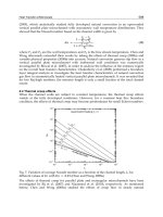
Vibratory (ultrasonic) equipment consists of an ultrasonic horn that is partly submerged in the liquid, which is
contained in a beaker (Fig. 5). The vibration, typically at 20 kHz frequency, generates negative pressure for cavitation
nucleation and growth, and positive pressure for cavity collapse in a small, stationary volume of the liquid. The specimen
is either mounted on the horn tip (moving specimen) or at a fixed distance (a few millimeters) below the horn tip
(stationary specimen).
Fig. 5 Vibratory cavitation device in wh
ich specimen is either attached to or held below a horn oscillating in the
lower kilohertz frequency range. Source: Ref 5
This test device is used for accelerated testing and lends itself to the study of interaction mechanisms with corrosion.
Because the cavity size distribution is not the same as in the flow channel equipment, direct comparisons are not
advisable. However, because the equipment is easy to use, it is widely applied to cavitation erosion resistance screening.
Furthermore, ASTM G 32 describes the equipment and procedures for this test.
Cavitating Jet. Two variations of this technique have been described. In type I, a hydraulic pump with an accumulator
delivers the test liquid through a sharp-entry parallel-bore nozzle, which discharges a jet of liquid into a chamber at a
controlled pressure (Ref 34). In type II, a high-pressure nozzle with an internal center body is used to create the low
pressure to initiate the cavitation (Ref 35, 36). Cavitation starts in the vena contracta region of the jet within the nozzle
(type I) or at the end of the center body (type II) before ejecting as a cloud of cavities around the emerging jet (type I) or
in the center of the jet (type II). The specimen is placed in the path of the jet at a specific stand-off distance from the
nozzle tip. The cavities collapse on the specimen, thereby causing erosion of the test material.
The advantage of this technique is that it is an accelerated test method that offers the possibility of control and, thereby,
allows the possibility of changing most of the cavitation parameters. Furthermore, the cavity size distribution resembles
that of a real flow situation more than does that produced in the vibratory system. The technique is currently under
consideration by ASTM as a standard test method.
Other Techniques. Rotating disk test equipment has been used in earlier cavitation studies (Ref 37, 38, 39, 40). Such
equipment consists of a rotating disk with specimen holder and cavitation sites (that is, holes in the disk) submerged in the
liquid. The liquid is kept relatively stable in a chamber where the disk is rotated. This technique is no longer in common
use; however, it can be used, for example, to simulate cavitation occurring in pump impellers.
Means of Combating Erosion
Materials Selection and Development. It is clear from the current understanding of deformation mechanisms in
metals and alloys, and from the dynamic and localized nature of cavitation loading, that materials selection for erosion
resistance should be based on the ability of alloys to absorb the impact energy by a nondestructive strain mechanism, such
as twinning, stacking-fault formation, or a stress-induced martensitic-type phase transformation. Unfortunately, most
standard mechanical testing is quasistatic in nature, and most cavitation erosion testing comprises weight loss
measurements without any determination of the mechanism of material loss. Consequently, mechanical property
databases do not usually contain the type of information necessary for appropriate materials selection.
Similarly, there has been little effort to develop materials specifically for their erosion-resistant properties. However, the
success of the initial research into the development of the iron-base IRECA alloys, which was based on a knowledge of
the required deformation mechanisms and understanding of the compositional factors necessary to ensure that the alloy
could deform in the appropriate manner, suggests that this is indeed a feasible approach and should be pursued.
Coatings and Surface Treatments. Coating technology is one of the more rapidly growing technologies in the field
of materials. It is clear that the selection of the base material for its bulk properties and a coating/surface treatment for its
resistance to environmental factors is the wave of the future. A combination of the development of materials specifically
designed for erosion resistance and the appropriate technique for the application of these materials as a coating would be
the optimum solution. Suitable coating techniques also allow for regeneration of parts that have been rendered unusable
by erosion.
Other measures described below include design, air injection, and control of the operating temperature or pressure.
System design represents the best way to either reduce or eliminate cavitation erosion. Therefore, fluid flow systems
should be designed to minimize the changes in flow pressure that occur when the velocity is either increased or decreased,
usually as a result of constrictions or changes in the direction of the flow. Similarly, the elimination of vibrations or the
reduction in their amplitude would reduce the problems of cavitation erosion in many types of machinery. If cavitation
cannot be eliminated, the cavitating regions should be designed to allow the cavities to collapse as far away from a solid
surface as possible or to decrease the concerted collapse mode of the cavity cluster (Ref 9).
Air injection into a cavitating fluid has been shown to be an effective method of reducing the intensity of erosion. The
air creates bubbles and partly fills the cavities as they are formed, which prevents their complete collapse, thereby
significantly reducing the magnitude of the shock wave emitted or the impact pressure of the microjets. The air also
significantly changes the dynamic properties of the liquid, that is, the shock-wave velocity and its attenuation.
Control of Operating Temperature or Pressure. It is more difficult to nucleate cavities at temperatures that
approach the freezing temperature, T
F
, of the liquid and more difficult to collapse them at temperatures that approach the
boiling temperature, T
B
. Therefore, cavitation erosion intensity is at a maximum at temperatures in the middle range
between freezing and boiling. Consequently, a change in temperature that is close to either T
F
or T
B
will reduce the
cavitation intensity and, thus, the degree of erosion. Similarly, increasing the hydrostatic pressure makes nucleation of
cavities more difficult, but increases the erosive power of the cavities, whereas decreasing the collapse pressure makes
collapse less intense.
More comprehensive discussions of the influence of various cavitation parameters on the resulting erosion are given in a
number of reviews (Ref 5, 41, 42).
The salient conclusions that can be made about cavitation erosion are:
• No materials are immune to cavitation erosion, as some are to corrosion; all will eventually erode
• Metallic materials that exhibit stress-
induced phase transformations have the highest erosion resistance.
Further development of alloys specifically for their erosion resistance is to be encouraged
• The combination of erosion and corrosion can be either syne
rgistic or less harmful than either process
alone. Unfortunately, there do not appear to be any general rules; therefore, each combination of
material, environment, and erosion conditions must be evaluated
• Coating technologies, particularly laser processing, offer great potential both in providing tailor-
made
erosion resistance to structures that are selected for their bulk properties and in repairing and
regenerating eroded surfaces
References
1. Lord Rayleigh, Philos. Mag., Vol 34, 1917, p 94-98
2. L. van Wijngaarden, 11th International Congress of Applied Mechanics (Munich), 1964
3. K.A. Mørch, Dynamics of Cavitation Bubbles and Cavitating Liquids, Erosion,
C.M. Preece, Ed.,
Academic Press, 1979, p 309-355
4. M.S. Plesset and R.B. Chapman, J. Fluid Mech., Vol 47, 1971, p 283-290
5. C.M. Preece, Cavitation Erosion, Erosion, C.M. Preece, Ed., Academic Press, 1979, p 249
6. C.M. Preece and I.L.H. Hansson, A Metallurgical Approach to Cavitation Erosion,
Advances in the
Mechanics and Physics of Surfaces,
R.M. Latanision and R.J. Courtel, Ed., Harwood Academic Publishers,
1981, p 191-253
7. B. Vyas and C.M. Preece, Cavitation-Induced Deformation of Aluminum,
Erosion, Wear and Interfaces
with Corrosion, ASTM, 1973
8. I.L.H. Hansson and K.A. Mørch, Compar
ison of the Initial Stage of Vibratory and Flow Cavitation Erosion,
5th International Conference on Erosion by Liquid and Solid Impact,
Cavendish Laboratory, Cambridge
University, 1979
9. I.L.H. Hansson and K.A. Mørch, The Influence of Cavitation Guide Va
nes on the Collapse of Cavity
Clusters and on the Resulting Erosion,
11th Symposium of the IAHR Symposium on Operating Problems of
Pump Stations and Power Plants (Amsterdam), International Association for Hydraulic Research, 1982
10.
C.M. Preece and C.W.
Draper, The Effect of Laser Quenching the Surfaces of Steels on Their Cavitation
Erosion Resistance, Wear, Vol 67, 1981, p 321
11.
E.B. Flint and K.S. Suslick, The Temperature of Cavitation, Science, Vol 253, 1991, p 1397-1399
12.
R. Simoneau et al., Cav
itation Erosion and Deformation Mechanisms of Ni and Co Austenitic Stainless
Steels, 7th International Conference on Erosion by Liquid and Solid Impact,
Cavendish Laboratory,
Cambridge University, 1987
13.
M.J. Kenn and A.D. Garrod, Cavitation Damage and the Tarbela Tunnel Collapse of 1974, Proc.
Inst. Civil
Eng., Vol 70, 1981, p 65
14.
C.M. Preece, S. Vaidya, and S. Dakshinamoorthy, The Influence of Crystal Structure on the Response of
Metals to Cavitation, Erosion: Prevention and Useful Applications, ASTM, 1979
15.
I.L.H. Hansson and K.A. Mørch, The Initial Stage of Cavitation Erosion of Aluminum in Water Flow,
J.
Phys., Vol D11, 1978, p 147-154
16.
E.H.R. Wade and C.M. Preece, Cavitation Erosion of Iron and Steel, Metall. Trans., Vol 9A, 1978, p 1299-
1310
17.
S. Vaidya and C.M. Preece, Cavitation-Induced Multiple Slip, Twinning, and Fracture Modes in Zinc,
Scr.
Metall., Vol 11, 1977, p 1143-1146
18.
S. Vaidya, S. Mahajon, and C.M. Preece, The Role of Twinning in the Cavitation Erosion of Cobalt Singl
e
Crystals, Metall. Trans., Vol 11A, 1980, p 1139-1150
19.
S. Vaidya and C.M. Preece, Cavitation Erosion of Age-Hardenable Aluminum Alloys, Metall. Trans.,
Vol
9A, 1978, p 299-307
20.
R. Schulmeister, Proceedings of the 1st International Conference on Rain Erosion,
Royal Aircraft
Establishment, United Kingdom, 1965
21.
D.A. Woodford, Metall. Trans., Vol 3, 1978, p 1137
22.
J.W. Tichler and A.W.J.D. Gee, 3rd International Conference on Rain Erosion,
Royal Aircraft
Establishment, United Kingdom, 1974
23.
T.F. Pedersen, S. Pedersen, and I.L.H. Hansson, Subsurface Deformation Studies of Cavitation Eroded FCC
Materials, 6th International Conference on Erosion by Liquid and Solid Impact,
Cavendish Laboratory,
Cambridge University, 1983
24.
A.P. Jardine, Y. H
oran, and H. Herman, Cavitation Erosion Resistance of Thick Film Thermally Sprayed
NiTi, Proceedings of Symposia on High Temperature Intermetallics,
Vol 213, Materials Research Society,
1991, p 815-820
25.
X X. Guo, H. Herman, and S. Rangaswamy, Cavitation Erosion of Plasma Sprayed WC/Co,
Advances in
Thermal Spraying, Pergamon Press, 1986, p 37-41
26.
S. Sampath, G.A. Bancke, and H.R. Herman, Plasma Sprayed Ni-Al Coatings, Surf. Eng.,
Vol 5 (No. 4),
1989, p 293-298
27.
R.J. Crisci, C.W. Draper, and C.M. Preece, Cavitation Erosion Resistance of Laser Surface Melted Self-
Quenched Fe-Al Bronze, Appl. Opt., Vol 21, 1982, p 1730
28.
W.W. Hu, et al., Cavitation Erosion of Ion-Implanted 1018 Steel, Mater. Sci. Eng., Vol 45, 1980, p 263-268
29.
C.M. Preece and
E.N. Kaufmann, The Effect of Boron Implantation on the Cavitation Erosion Resistance of
Copper and Nickel, Corros. Sci., Vol 22, 1982, p 267-281
30.
S. Pedersen and I.L.H. Hansson, Nickel Coatings for Cavitation Erosion Resistance of Brass Components,
6th International Conference on Erosion by Liquid and Solid Impact,
Cavendish Laboratory, Cambridge
University, 1983
31.
H. Herman, Plasma-Sprayed Coatings, Sci. Am., Vol 256 (No. 9), 1988, p 112-117
32.
W. Amende, private communication, 1989
33.
B. Vyas and I.L.H. Hansson, The Cavitation Erosion-Corrosion of Stainless Steel, Corros. Sci.,
Vol 30 (No.
8/9), 1990, p 761-770
34.
A. Lichtarowicz and P.J. Scott, Erosion Testing with Cavitating Jet,
5th International Conference on
Erosion by Liquid and Solid Impact, Cavendish Laboratory, Cambridge University, 1979
35.
P.A. March, Evaluating the Relative Resistance of Materials to Cavitation Erosion: A Comparison of
Cavitation Jet Results and Vibratory Results, Cavitation and Multiphase Flow Forum, FED, 1987
36.
P.A. March, Cavitating Jet Facility for Cavitation Erosion Research,
Symposium on Cavitation Research
Facilities and Techniques, American Society of Mechanical Engineers, 1987
37.
J.Z. Lichtman, D.H. Kallas, C.K. Chatten, and E.P. Cochran, Cavitation E
rosion Resistance of Structural
Materials and Coatings, Corrosion, Vol 17, 1961, p 497-505
38.
J.Z. Lichtman and E.R. Weingram, The Use of a Rotating Disc Apparatus in Determining Cavitation
Erosion Resistance of Materials, Symposium on Cavitation Research Facilities and Techniques,
American
Society of Mechanical Engineers, 1964
39.
A. Thiruvengadam, A Comparative Evaluation of Cavitation Damage Test Devices,
Cavitation Research
Facilities and Techniques, American Society of Mechanical Engineers, 1964
40.
P. Veerabhadra Rao, Correlating Models and Prediction of Erosion Resistance to Cavitation and Drop
Impact, J. Test. Eval., 1976, p 3-14
41.
H. Wiegand and R. Shulmeister, Investigations with a Vibratory Apparatus on the Influence of Frequency,
Amplitude, Pressure, and Temperature on Material Destruction by Cavitation, Motortechnische Zeitschrift,
Vol 29 (No. 2), 1968, p 41-50
42.
S. Pedersen, "Cavitation Erosion: Vibratory Cavitation and Cavitation Erosion of Metals," Ph.D. thesis,
Laboratory of Applied Physics, Technical University of Denmark, 1986
Liquid Impingement Erosion
Frank J. Heymann (retired), Westinghouse Electric Corporation
Introduction
LIQUID IMPINGEMENT EROSION has been defined as "progressive loss of original material from a solid surface due
to continued exposure to impacts by liquid drops or jets" (Ref 1). The operative words in this definition are "impacts by
liquid drops or jets": liquid impingement erosion connotes repeated impacts or collisions between the surface being
eroded and small discrete liquid bodies.
Excluded from this definition are erosion mechanisms due to the impingement of a continuous jet, due to the flow of a
single-phase liquid over or against a surface, due to a cavitating flow, or due to a jet or flow containing solid particles
although all these can produce erosion (progressive loss of solid material) at least under some conditions. Some of these
mechanisms will, however, be discussed briefly in order to distinguish them clearly from the primary subject.
The significance of the discrete impacts is that they generate impulsive contact pressures on the solid target, far higher
than those produced by steady flows (see the discussion "Liquid/Solid Interaction Impact Pressures" later in this article).
Thus, the endurance limit and even the yield strength of the target material can easily be exceeded, thereby causing
damage by purely mechanical interactions. In some circumstances the damage can also be accelerated by conjoint
chemical action.
At sufficiently high impact velocities, solid material can be removed even by a single droplet (or other small liquid body).
Much of what is currently known about the liquid/solid interactions in liquid impingement has been determined through
laboratory experiments and analytical modeling involving single impacts.
Liquid impingement erosion in its advanced stages is characterized by a surface that appears jagged, composed of sharp
peaks and pits (Fig. 1). A possible reason for this will be given later.
Fig. 1 T
wo portions of a steam turbine blade that has experienced liquid impingement erosion. The portion on
the left was protected by a shield of rolled Stellite 6B brazed onto the leading edge of the blade; the portion on
the right is unprotected type 403 stainl
ess steel. Note the difference in degree of erosion. Normally such
erosion does not impair the blade's function. Both at 2.5×
A very comprehensive treatment and review of liquid impact erosion can be found in Ref 2; in particular the chapters
therein by Adler (Ref 3) and by Brunton and Rochester (Ref 4). Reference 5 contains some now classic studies that
provided the foundation for subsequent work. Many other contributions to this field are found in several ASTM
symposium volumes (Ref 6, 7, 8, 9, 10) and in the proceedings of the international "Rain Erosion" and "Erosion by Liquid
and Solid Impact" (or "ELSI") conferences (Ref 11, 12, 13, 14, 15, 16, 17). Individual papers from some will be cited in
context.
Acknowledgements
The author would like to thank John E. Field of Cambridge University, George F. Schmitt, Jr. of the Air Force Materials
Laboratory and Westinghouse Electric Corporation for supplying photographs. Additional thanks are due to George
Schmitt for also supplying information on the current state of rain erosion protection and providing valuable suggestions
for improving this article.
Occurrences in Practice
It is quite difficult to propel liquid droplets to high velocities without breaking them up, and liquid impingement erosion
haas become a practical problem primarily where the target body moves at high speeds and collides with liquid drops that
are moving much more slowly. Almost all the work done in this subject has been in connection with just two major
problems: "moisture erosion" of low-pressure steam turbine blades operating with wet steam, and "rain erosion" of
aircraft or missile surfaces and helicopter rotors.
Whenever vapor or gas flows carrying liquid droplets impinge upon solid surfaces as in nuclear power plant pipes and
heat exchangers, for example erosion can also occur. However, the probable impact velocities and impact angles are
such as to make "pure" liquid impingement erosion an unlikely mechanism. It is much more likely that an "erosion-
corrosion" mechanism is then involved (see the discussion of "Impingement Attack and Erosion-Corrosion" later in this
article).
Steam Turbine Blade Erosion. Moisture erosion of low-pressure blades has been a problem throughout steam
turbine history, and remains a concern today. In the last stages of the low-pressure turbine, the steam expands to well
below saturation conditions, and a portion of the vapor condenses into liquid. Although the condensation droplets are very
small, some of them are deposited onto surfaces of the stationary blades (guide vanes), where they coalesce into films or
rivulets and migrate to the trailing edge. Here they are torn off by the steam flow, in the form of much larger droplets.
These large droplets slowly accelerate under the forces of the steam acting on them, and when they are carried into the
plane of rotation of the rotating blades, they have reached only a fraction of the steam velocity. As a result, the blades hit
them with a velocity that is almost equal to the circumferential velocity (wheel speed) of the blades, which can be as high
as 650 m/s (2100 ft/s) in a modern 3600 rpm turbine. References 18 and 19 describe these processes in detail. The same
basic phenomenon can, of course, occur in wet vapor turbines operating with other working fluids, such as sodium or
mercury.
The principal remedies in modern turbines include extracting moisture between blade rows, increasing axial spacing
between stator and rotor to permit droplets to be accelerated and broken up, and making the leading edge of the blade
more resistant to erosion. This last remedy has been accomplished by local flame hardening of the blade material, by
brazed-on "shields" of Stellite (Fig. 1), or in some cases by shields of tool steel or weld-deposited hardfacing. Tests on
many blade and shield materials are reported in Ref 20 and 21. The base material for present-day low-pressure blades is
usually a 12% Cr martensitic stainless steel, a 17Cr-4Ni precipitation-hardening stainless steel, or, more rarely, a titanium
alloy.
Recently, success has been claimed for new "self-shielding" blade alloys that harden under the action of the impacts. One
such alloy is Jethete M152, a martensitic steel containing about 11% Cr, 2.9% Ni, 1.6% Mo, and 0.3% V. Other new
approaches that have been investigated include plasma-deposited Stellite and an ion-plated chromium-tin multilayer
coating; however, it is doubtful that relatively thin coatings can provide long-term protection.
The evaluation and prediction of steam turbine blade erosion is very complex; recent contributions include Ref 22 and 23.
Aircraft Rain Erosion. Rain erosion became a major problem in the 1950s, when military aircraft reached transonic
and supersonic speeds. The impact of rain drops, 2 mm (0.08 in.) or more in size, on unprotected aluminum alloy
surfaces, optical and infrared windows, and radomes caused severe erosion which seriously limited operational time in
rain storms. This resulted in many government-funded research projects into erosion mechanisms as well as development
and evaluation of protective coatings. Reference 24 gives an overview of the rain erosion problem, with special reference
to radomes. The current status concerning remedies has been summarized as follows by Schmitt (Ref 25):
Protection of aircraft radomes and composite surfaces is accomplished with two classes of
elastomeric coatings
polyurethanes for widespread lower temperature applications, and
fluorocarbons where elevated temperatures (above 177 °C, 350 °F) or special requirements
(camouflage colors, thermal flash protection) are involved.
For applications where su
personic rain erosion is a concern, the inherent erosion resistance of the
base materials combined with streamline geometry to reduce impact angles is the most often
used approach. Another aerodynamic technique is to utilize the shock waves to shatter and
fragment the raindrops into very small pieces that produce less damage. For hemispherical
domes where impact angles must be large (near normal), protective coatings of boron phosphide,
germanium carbon and diamond are being pursued, but they are restricted
to velocities less than
Mach 2. At extremely high velocities, protection at high impact angles may require metal tips or
sacrificial layers even though a performance penalty must be paid. In many cases, lack of
adequate materials and potential catastrophi
c failure simply precludes operation at high
supersonic speed in rainy environments.
References 8, 9, 10, 11, 12, 13, 14, 15, 16, and 17 contain numerous papers on evaluation of materials and coatings for
rain erosion applications. Among the most recent are investigations of infrared window materials, slip-cast fused silica,
and hard carbon-coated germanium in Ref 17; polyurethane and fluoroelastomer coated composite constructions,
composite materials for radomes, new materials for radomes, and infrared windows (including polyethersulfone,
polyetherimide, polyetherketone, and germanium) in Ref 16; and slip-cast fused silica, boron-aluminum composites,
composite and honeycomb structures, polytetrafluoroethylene (PTFE) and polymethylmethacrylate (PMM) in Ref 15.
As mentioned earlier, rain erosion also poses a threat to missile surfaces and helicopter rotors. Figure 2 shows the
catastrophic failure of a missile dome due to rain erosion effects.
Fig. 2 Rain erosion effects on a Maverick missile dom
e made of coated zinc sulfide that was exposed for 10 s at
a speed of about 210 m/s (690 ft/s). The dome itself suffered catastrophic damage, and erosion is also seen on
the filled elastomeric mounting ring. Courtesy of G.F. Schmitt, Jr., Materials Laborat
ory, Wright Research and
Development Center, Department of the Air Force
Relationship to Other Erosion Processes
Continuous Jet Impingement. Impingement of a high-velocity continuous jet can cause material removal, and that
fact has led to the development of jet-cutting technology used in quarrying, mining, and material cutting. While there is
some overlapping with erosion research, much of the literature is found in the "American Water Jet Conferences" and the
"International Conferences on Jet Cutting Technology."
Steady continuous jet impingement produces only stagnation pressure on the target, whereas discrete impacts produce
much higher shock-wave or "water-hammer" pressures. Thus, high supply pressures are needed to achieve material
removal with truly continuous jets. This has led jet-cutting research to develop techniques for producing moving and
oscillating jets, pulsating jets, and cavitating jets, all of which serve to introduce something akin to discrete impact
conditions (also, jets laden with abrasive particles are used). References 26 and 27 describe these techniques.
Rough comparisons of test data suggest that the erosion rate due to a continuous jet can be from one to five orders of
magnitude lower than that due to the same quantity of liquid impinging at the same velocity but in the form of droplets.
Cavitation Erosion. Whereas liquid impingement connotes a continuous vaporous or gaseous phase containing discrete
liquid droplets, cavitation connotes a continuous liquid phase containing discrete vaporous or gaseous bubbles or cavities.
Despite this seeming antithesis, the nature of cavitation damage and liquid impingement damage has many similarities.
Both, in fact, are due to small-scale liquid/solid impacts. In cavitation, micro-jet impacts have been shown to occur in the
asymmetrical collapse of cavitation bubbles adjacent to a solid surface, although shock waves generated by collapsing
cavity clusters may also contribute to damage.
The relative resistance of materials to the two types of erosion is much the same, the damage appearance is similar, the
complicated time dependence of the erosion rate is similar (see the section "Time Dependence of Erosion Rate" in this
article), and historically cavitation tests have been used to screen materials for service in liquid impingement
environments, and vice versa. In some practical cases, it is not clear whether the mechanism causing erosion was
impingement or cavitation erosion. One such example is the heavily eroded dynamometer stator shown in Fig. 3. Erosion
in such machines has often been characterized as cavitation erosion; however, the author believes it to be liquid impact
erosion caused by the discrete streams of water issuing from the rotor pockets and sweeping across the stator vanes. This
is supported by dynamic pressure transducer spectra which were dominated by discrete spikes at the rotor vane passing
frequency, but did not show the characteristic signature of cavitation. In addition, injection of air bubbles, which can
inhibit cavitation, had no influence on the signals or on the erosion.
Fig. 3 Severe erosion of copper-manganese-
aluminum stator vanes in a hydraulic dynamometer. Each vane
has lost about 10 cm
3
(0.6 in.
3
) of material. See text for a discussion of the erosion mechanism.
For additional information on cavitation damage, see the article "Cavitation Erosion" in this Volume.
Solid Particle Erosion. It might easily be assumed that solid particle erosion would have many similarities to liquid
impingement erosion, since both involve the impact of small discrete bodies. This is not the case, however, because the
damage mechanisms, the effects of impact variables, and the response of materials are all quite different.
For example, the resistance of common engineering alloys to liquid impingement ranges over several orders of
magnitude, whereas most common ductile alloys have about the same resistance to solid impingement; liquid
impingement erosion rates vary with about the 5th power of impact velocity, whereas solid particle erosion varies with
about the 2.5th power; liquid impingement erosion is greatest with normal (perpendicular) impacts, whereas solid particle
erosion in ductile alloys peaks with impacts some 60 to 70° away from perpendicular; and finally, liquid impingement
erosion exhibits a complicated time dependence, whereas the erosion rate due to solid particle impingement is essentially
linear. See the article "Solid Particle Erosion" in this Volume for further details.
Impingement Attack and Erosion-Corrosion. There are many practical situations where material loss occurs in
the presence of flowing fluids but cannot be fully explained by purely mechanical action such as liquid impingement,
solid particle impingement, or cavitation. Only recently has a substantial amount of scientifically oriented work on these
phenomena been reported in the literature.
"Impingement attack" is a term sometimes used for material loss in tube bends and heat exchanger tube entrances, where
the forces of unsteady, turbulent, or bubbly flows are believed to remove protective oxide layers and thus permit
continuing and accelerated corrosion. "Wire drawing" is a term used for a grooving type of erosion produced in small
gaps such as valve seats and component joints with a high pressure drop across them. This type of erosion could be due to
localized cavitation or to erosion-corrosion.
"Erosion-corrosion" can refer to any conjoint (synergistic) action between corrosive and erosive processes, such that the
resulting material loss rates are greater than the sum of the individual processes taken by themselves. Corrosive actions in
the presence of solid particles, slurries, and sliding wear are covered in detail in the articles "Solid Particle Erosion,"
"Slurry Erosion," and "Corrosive Wear" in this Volume.
For purely fluid systems, some recent work on "corrosive-erosion" has emphasized a mechanism in which impulsive
mechanical interactions play little or no role. For example, the flow of liquid or droplets along a carbon or low-alloy steel
surface prevents equilibrium in the corrosive process and results in continuing chemical dissolution of the protective
oxide (magnetite) layer (Ref 28). This is more accurately called "flow-assisted corrosion."
Only a few references can be cited here. Keck and Griffith (Ref 29) propose models for both convection-assisted oxide
dissolution and for oxide fatigue by liquid droplet impacts. Coulon (Ref 30) distinguishes mechanisms by the flow
velocity causing them: corrosion, 0 to 10 m/s (0 to 35 ft/s); corrosion-erosion, 10 to 50 m/s (35 to 165 ft/s); erosion-
corrosion, 50 to 200 m/s (165 to 655 ft/s); and erosion, >200 m/s (>655 ft/s). Henzel et al. (Ref 31) give an update on
experience and remedies. Both Ref 30 and 31 provide empirical schemes for estimating material loss due to erosion-
corrosion, including factors relating to material, flow velocity, and temperature, as well as geometry factors borrowed
from another empirical model by Keller (Ref 32).
Mechanisms of Liquid Impact Erosion
Liquid/Solid Interactions Impact Pressures. The high-velocity impact of a liquid drop against a plane solid
surface produces two effects that result in damage to that surface: high contact pressure, which is generated in the area of
the impact, and subsequent liquid "jetting" flow along the surface, radiating out from the impact area (Ref 33). A first
approximation of the average impact pressure, before radial outflow initiates, is the one-dimensional water-hammer
pressure; that is, pressure generated in the impact of an infinite flat liquid surface against an infinite flat rigid surface. In
this case a plane shock wave is formed at the instant of impact and travels into the liquid, bringing to rest one "layer" after
another.
This impact or shock pressure, P, can be defined as:
P = CV
where is the liquid density, C is the shock wave velocity in the liquid, and V is the impact velocity. For practical impact
velocities, this can be approximated by:
P = C
0
V (1 + kV/C
0
)
where C
0
is the acoustic velocity of the liquid, and k = 2 for water. For example, for water impacting at 500 m/s (1640
ft/s), this pressure is about 1250 MPa (180 ksi) considerably above the yield strength of many alloys. The stagnation
pressure of a continuous jet ( V
2
/2) at that speed is about one-tenth of the former.
The real situation is much more complicated, because of the roundness of the impacting droplet and the elastic and plastic
deformations of the solid surface. Although much work has been done on this topic in recent years (for example, Ref 34,
35, 36, 37), a complete understanding has not yet been achieved. However, the following salient features (see Fig. 4) are
now widely accepted for the impact of a round drop on a rigid surface:
• At the
initial instant of impact, contact is made at a point. Because the droplet radius of curvature is
initially infinite compared to the contact radius, quasi-one-
dimensional conditions prevail and a shock
wave of the one-dimensional impact pressure is formed
at that instant and begins to travel up into the
drop (Fig. 4a)
• As the contact area spreads out, its perimeter at fi
rst is moving radially outward at a speed greater than
the shock velocity; consequently an obliquely attached bulbous shock front is formed enclosing the
compressed liquid and no free outflow can take place (Fig. 4
b). During this stage, the highest impact
pressure is found at the growing contact perimeter, where its value gradually increases up to about 3
C
0
V, while that at the impact center decreases
• At some point, defined by a critical contact angle,
c
, the conditions for an attached shock are no longer
met; the shock front then detaches from the solid surface and moves up along the surface of the droplet.
The compressed liquid is now free to spread or "jet" out laterally and relieve the contact pressures (
Fig.
4c). In experiments, however, actual jetting is not observed until the contact angle
has reached a value
significantly greater than the theoretical critical value
c
; the reasons for this behavior are not yet fully
understood. The maximum lateral jetting velocity is many times greater than the
impact velocity, but
theoretical prediction of its value is still uncertain.
Figure 5 shows high-speed photographs at various stages of the impact between a solid projectile and a gelatine droplet in
a laboratory apparatus. In this case the impact velocity was 110 m/s (360 ft/s) and the maximum jetting velocity 1170 m/s
(3840 ft/s).
Fig. 4
Idealized diagram of the early stages of liquid drop impact. (a) Initial contact. (b) Compressible stage
with attached shock front. (c) Detached shock and je
tting stage. See text for detailed discussion of these three
stages.
Fig. 5 High-speed photographs of the impact between a 10 mm (0.4 in.) diam two-
dimensional droplet of
gelatin and a metal slider moving at 110 m/s (360 ft/s) at intervals of 1 s. S denotes
the shock front, first
seen in frame b. Jetting is just visible in frame c and is labeled J in frame d. Note the reflection of the shock as
a rarefaction wave R in frames h through j, causing a region of cavitation indicated by F. In these photos, there
ha
s not yet been time for any gross spreading out of the droplet to occur. Courtesy of J.E. Field, Cavendish
Laboratory, University of Cambridge, United Kingdom
The liquid/solid interaction is further complicated when the solid surface becomes deformed from erosion, usually
exhibiting jagged peaks and craters. Then both the pressures and jetting patterns will be affected by where the initial
contact takes place, and by the size of the droplet in relation to topographic features. For example, a drop falling on a peak
or slope may not develop full impact pressure; one falling in a crater may produce increased pressures due to shock wave
collisions or "shaped charge" effects. This may explain the characteristic pitted appearance because if even shallow pits
are formed, subsequent material loss occurs preferentially in the pits and continues to deepen them.
Material Response Development of Damage. As described above, the solid surface is subjected to a multitude of
sharp pressure pulses and jetting outflows, each of very short time duration and acting on a very small area. What then
happens to the solid material is hard to generalize because it will depend on whether the solid is ductile or brittle, on its
microstructure, and on whether the impacts are severe enough to produce single-impact damage. Adler (Ref 3) lists the
primary causes of damage as direct deformation, stress wave propagation, lateral outflow jetting, and hydraulic
penetration. At impact, the formation of the shock front in the liquid is accompanied by corresponding stress waves
propagating into the solid; the solid response is therefore also impulsive and governed by its dynamic rather than static
mechanical properties.
In ductile materials, a single intense impact may produce a central depression, with a ring of plastic deformation around it
where the jetting outflow may remove material by a tearing action (Fig. 6). With less intense but repeated impacts, there
is no immediate material loss, but randomly disposed dimples gradually develop, and the surface undergoes gradual
deformation (often characterized by twinning) and work hardening. Metallographic and x-ray diffraction studies have
shown that during this "incubation stage," these effects eventually extend to 30 to 50 m below the surface, thereafter
remaining about the same as actual erosion (material loss) then begins and progresses. The material loss may occur
through propagation of fatiguelike cracks that eventually intersect to release erosion fragments. The fractures have often
been described as transgranular. This process can be assisted by tearing that is due to increased liquid forces on irregular
surface steps and fissures. In materials with pronounced nonuniform structure, damage will initiate at weak spots or in the
weaker components. Figures 7 and 8 illustrate the character of erosion damage in a martensitic stainless steel (AISI type
403) and Stellite 6B, respectively.
Fig. 6 Deformation due to a single impact on aluminum impacted by a short discrete
jet of water at 750 m/s
(2460 ft/s). Note the central depression, which is of similar diameter to the impacting jet, and the
circumferential surface ripples surrounding it. Courtesy of J.E. Field, Cavendish Laboratory, University of
Cambridge, United Kingdom
Fig. 7
Character of erosion in type 403 martensitic stainless steel. (a) Macrograph of eroded area. 10×. (b)
Unetched sec
tion. 10×. (c) Section through several pits. GRARD II etch. 50×. (d) Enlarged portion of (c).
200×. Courtesy of Westinghouse Electric Corporation
Fig. 8
Character of erosion in Stellite 6B alloy. (a) Unetched section. 10×. (b) and (c) Etched sections through
specific pits. Both at 200×
In brittle materials, circumferential cracks may form around the impact site that are caused by tensile stress waves
propagating outward along the surface (Fig. 9). In thin sheets subjected to impacts, material can spall off the inside
surface due to the compressive stress wave from the impact reflecting there as a tensile wave.
Fig. 9
Damage due to a single impact on a brittle material (zinc sulfide) caused by a short discrete jet of 0.8
mm (0.03 in.) (corresponding to a 5 mm, or 0.2 in., droplet) impacting at 300 m/s (985 ft/s). Note apparently
undamaged central area of about 1.2 mm (
0.05 in.) surrounded by circumferential cracks caused by the
Rayleigh waves induced by the impact. Courtesy of J.E. Field, Cavendish Laboratory, University of Cambridge,
United Kingdom, from Ph.D. thesis by D. Townsend
For materials and composite structures used in aerospace applications, it is difficult to generalize damage mechanisms.
For example, in thermosetting polymers or chopped fiber-reinforced composites, the damage takes the form of chunking
(removal of large-size lumps of material) from the surface (Ref 25). Furthermore, the initial measure of damage for
radome and infrared window materials is not gross material removal, but impairment of electromagnetic transmission
characteristics, which leads to loss of function. In the extreme, however, damage can be catastrophic, as shown in Fig. 2.
Corrosion Interactions. More research on corrosion interactions has been done for cavitation than for liquid
impingement, but the general observations described below can apply to both.
In the early days before high impact pressures were understood, it was often supposed that liquid impingement as well as
cavitation damage had to be largely or significantly corrosive in nature. It is now recognized, and has been proven
experimentally, that such erosion can occur without any corrosive component. Moreover, under impingement of high
intensity, material loss can occur so rapidly that corrosion even if otherwise possible does not have time to play a role.
Nevertheless, at intermediate mechanical intensities there is opportunity for corrosion to weaken the material and
facilitate its removal by the mechanical impact forces. Several investigators have shown some parallels between erosion
and corrosion fatigue behavior.
Time Dependence of Erosion Rate
Qualitative Description. Liquid impingement erosion shares with cavitation erosion a unique characteristic that
makes accurate long-term predictions or extrapolations of erosion nearly impossible. This is the very nonlinear nature of
the progress of erosion with time, under constant impingement conditions (Ref 38). Qualitatively, the so-called "erosion-
time pattern" depicted in Fig. 10 is generally composed of the following stages:
• Incubation stage, during which little or no material loss oc
curs, although roughening and metallurgical
changes take place in the surface. However, an incubation period may not appear if the impact
conditions are severe enough for each single impact to cause material loss
• Acceleration stage, during which the erosion rate increases rapidly to a maximum
• Maximum rate stages,
during which the erosion rate remains constant or nearly so. The erosion rate for
this stage is most commonly quoted as a single-
number result of an erosion test. However, some tests
show only a fleeting peak in the erosion rate-versus-time curve, with no prolonged steady rate
• Deceleration (or attenuation) stage,
during which the erosion rate declines to some fraction (often from
to ) of the maximum rate
• Terminal (or final steady-state) stage, during which the rate remains con
stant once again indefinitely.
However, some tests do not show this stage, and the erosion rate either continues to decline or goes into
a series of fluctuations. With some brittle materials or coatings, the rate can increase in what is called a
"catastrophic stage"
Fig. 10
Characteristic erosion versus time curves. (a) Cumulative erosion (mass or volume loss) versus
exposure d
uration (time, or cumulative mass or volume of liquid impinged). (b) Corresponding instantaneous
erosion rate versus exposure duration obtained by differentiating curve (a). The following stages have been
identified thereon: A, incubation stage; B, acceler
ation stage; C, maximum rate stage (sometimes called first
steady-state stage); D, deceleration stage; and E, terminal or final steady-state stage, if assumed to exist.
Figure 11 shows some nontypical curves that are sometimes encountered. All of the curves in Fig. 10 and 11 have been
derived from actual test curves in the literature.
Fig. 11
Less common types of cumulative erosion versus time curves sometimes obtained. (a) Curve without
incubation or acceleration stages, wit
h continuously decreasing rate (obtained in this case with very small
droplets and very high impact velocity). (b) Curve with continuously increasing erosion rate, resulting in
catastrophic damage (obtained in this case on titanium carbide). (c) Curve with
fluctuations in erosion rate
(obtained in this case on a titanium alloy)
Reasons for Time Dependence. The incubation and acceleration stages are easy to explain in qualitative terms if one
postulates that the removal of erosion fragments results from a fatiguelike failure mechanism. Then many impacts must
occur in one area for a fragment to be loosened from the surface. The statistical nature of the process then results in a
gradual transition the acceleration period from the incubation stage to the steady-state (maximum rate) stage.
The subsequent decrease in erosion rate is harder to explain, and most attempted explanations are somewhat conjectural
(Ref 38). Some have also been based on the statistics of the damage mechanisms, combined with changes in the surface
properties brought on by erosion itself. Some are based on the topographical changes in the surface: as the surface is
roughened, the surface area is increased, and more energy is needed to continue erosion. Also, liquid drops will now tend
to impact on the peaks or the slopes of the roughened surface; in both cases the impact pressures may be reduced. Finally,
the liquid retained in erosion craters has been supposed to cushion and protect the surface.
Implications for Testing and Prediction. Clearly, this complicated time dependence of erosion, and the variations
thereof, make it very difficult to define a single meaningful test result of an erosion test, or assign from that an erosion
resistance of a material, or predict long-term erosion behavior from a short test. Many authors in the literature have
proposed mathematical formulations for the erosion-time curve (or portions of it). Some of these have been essentially
empirical, some have been based on proposed analytical models for the erosion process; however none so far has
achieved general acceptance. See the discussion of "Comprehensive Prediction Methods and Erosion Theories" later in
this article for additional information.
For the purpose of reporting test results, ASTM Standard Practice G 73 for Liquid Impingement Erosion Testing (Ref 39),
as well as ASTM Standard Method G 32 for Vibratory Cavitation Erosion Testing (Ref 40) recommend that curves of
cumulative mass loss versus time be shown in a test report, since any other parameters (for example, erosion rates) must
be derived from that. For tabular data and comparisons (between materials or test conditions), ASTM G 73 prescribes
tabulating the maximum erosion rate and a nominal incubation period, which is simply the intercept on the time axis of
the maximum erosion rate line. In order to describe the longer-term behavior, some authors also use the terminal (final
steady-state) erosion rate and some parameter that defines the intersection of that line with the maximum-rate line or the
erosion axis (Fig. 12). Note that even this simplified model of the erosion-time pattern, consisting of three straight-line
segments, requires four experimentally or analytically derived parameters to define it.
Fig. 12 The erosion versus time curve from Fig. 10
, showing some numerical parameters that may be recorded
to characte
rize the test results. A, nominal incubation period; B, slope representing maximum erosion rate; C,
y-axis intercept of terminal erosion rate line; D, slope representing terminal erosion rate. ASTM G 73 (Ref 39
)
specifies that at least A and B be tabulated in any test report. Some authors have used E (y-
axis intercept of
maximum erosion rate line) in place of A; it tends
to be constant when some parameters (for example, impact
velocity) are varied.
The author's experience, in attempting to correlate test data from various sources, has been that the maximum erosion rate
is the most predictable by empirical relationships. However, this parameter alone cannot be used to predict long-term
erosion in the absolute sense, and there are indications that it does not predict it well even in the relative sense. Thus,
more work is certainly needed in reaching a generalized method for long-term erosion prediction.
Factors Affecting Erosion Severity
In order to understand the mechanics of erosion and to subsequently predict the erosion behavior of various materials,
there are a number of critical parameters that must be examined. Following a brief discussion of the dimensionless
parameters used for characterizing erosion, this section will review critical empirical observations regarding both
impingement variables (velocity, impact angle, droplet size, and physical properties of liquids) and erosion resistance of
materials, including the correlation between erosion resistance and mechanical properties and the effects of alloying
elements and microstructure. Empirical erosion prediction equations developed from ASTM-sponsored test programs are
also described.
Dimensionless Parameters for Describing Erosion
When a physical phenomenon is fully understood, it should be possible to describe it mathematically in terms of a
functional relationship between a set of dimensionless parameters. This ensures dimensional consistency in the functional
relationships, makes the equations independent of the set of units of measurement adopted, and can help ensure by use of
dimensional analysis that the correct number of independent parameters are included for each dependent parameter of
interest. Unfortunately, no such complete relationship for predicting erosion has been generally accepted to date, although
some authors have made attempts toward it. Although an extended discussion of this topic is beyond the scope of this
article, two dependent variables of interest in dimensionless form will be introduced. These are:
• The "rationalized erosion rate," R
e
, which is defined as the volume of the target material lost divided by
the volume of liquid impinged (where both pertain to the same area and the same time interval)
• The "rationalized incubation period," N
0
, which is defined as the number of stress pulses experienced by
a typical point on the target surface during the incubation period
In the following discussions, the "erosion rate" referred to is always the "maximum erosion rate" (see the previous section
of this article on "Time Dependence of Erosion Rate" ). The empirical data regarding incubation periods are much less
abundant, but several studies have suggested that the nominal incubation period defined in Fig. 12 is approximately
inversely proportional to the maximum erosion rate and, moreover, the product of the rationalized quantities R
e
N
0
is on
the order of unity (Ref 41).
Impingement Variables
Velocity Dependence/Threshold Considerations. It is conceptually very attractive to suppose that there is a
"threshold velocity" dependent on the material below which no erosion would occur, analogous to the endurance limit
in fatigue. Several investigators have presented evidence for such a threshold (Ref 22, 42), which may also depend on
droplet size (Ref 43). However, the author has found that most test data, from many sources, seem to better fit a simple
power law in which the rationalized maximum erosion rate varies with about the 4th to 5th power of impact velocity (Ref
44). For brittle materials, exponents as high as 6 to 9 have been reported (Ref 45). At low impact velocities, the
incubation period may become so long that no actual material loss takes place in a reasonable testing or operating time,
giving the appearance of a threshold. Thus, the question of a threshold phenomenon is not yet firmly settled.
Dependence on Impact Angle. It is generally considered that, to a first approximation, erosion depends on only the
normal component of the impact velocity; thus, because of the strong dependence on impact velocity, erosion is reduced
strongly as impacts become more glancing. Some investigators have suggested a small added contribution from the
tangential component, and intuitively one might suspect that once a surface becomes roughened by erosion, the effect of
the tangential component would become more pronounced.
Dependence on Droplet Size. By and large, test data show that R
e
decreases with drop size (Ref 41, 43); that is, a
given total amount of liquid does less damage if divided into smaller drops, even though this implies a greater number of
impacts on the surface. There is no obvious explanation for this phenomenon. One suggested explanation is that it is due
to the shorter time duration of each pressure pulse with smaller drops; another postulates that it is a material-related size
effect similar to those in fatigue notch sensitivity or in metal cutting, where the spatial extent of imposed stresses must
exceed some characteristic dimension.
Dependence on Liquid Properties. Most liquid impact erosion tests have been conducted with water at near normal
atmospheric conditions. Knowledge of how erosion varies with the physical properties of the liquid is necessary if one
wants to extend empirical relationships to other liquids and conditions, and also if one wants to construct a true analytical
model that is dimensionally consistent. The results of one investigation (Ref 46) suggested dependencies on
approximately the 2nd to 2.5th power of liquid density and the to power of the inverse of viscosity; the dependence
on acoustic velocity (which theoretically enters into impact pressure as well as acoustic impedance relationships)
remained unclear. More work in this area is desirable.
Erosion Resistance
What Is Erosion Resistance? In the absence of any widely accepted, dimensionally consistent, analytical model for
the erosion process, it is impossible to specify an independent definition, dimensions, or units for the property of erosion
resistance. Although a concept of "erosion strength" having the units of a mechanical strength or strain energy property
has been proposed (Ref 42), this has not gained wide acceptance.
All one can do is to conduct erosion tests and compare the results between different materials. Generally one material is
selected as a reference material and results for the others are referred to that. ASTM G 40 (Ref 1) defines a "normalized
erosion resistance" as follows: "The volume loss rate of a test material, divided into the volume loss rate of a specified
reference material similarly tested and similarly analyzed . . ." In Ref 44 the reference material is austenitic stainless steel
of hardness HV 170. ASTM G 73 (Ref 39) defines an "erosion resistance number" based on up to three reference
materials covering a range of resistances. Some recent cavitation test programs have adopted stainless steel type 308 weld
overlay as the reference.
Correlations with Mechanical Properties. Hardness has a strong effect on erosion resistance, but by itself is not a
sufficient indicator. For the same or similar materials, erosion resistance generally varies with about the 2nd to 2.5th
power of Vickers hardness number, but that does not necessarily apply when different types of materials are compared.
For example, austenitic stainless steels have higher resistance than martensitic stainless steels of the same hardness, and
cobalt-base alloys (for example, Stellites) have an even higher resistance in relation to hardness (Ref 44).
Other parameters based on mechanical properties have been proposed as indicators of erosion resistance. These include
the strain energy to fracture parameter, and the so-called "ultimate resilience" ( /2E), where s
u
is ultimate strength and
E is modulus of elasticity; neither is very successful over a broad range of materials (Ref 44).
Since liquid impingement and cavitation erosion is due to repeated stress pulses and thus related to fatigue, some authors
have tried unsuccessfully to correlate resistance with endurance limit or finite fatigue life. Recently, however, Richman
and McNaughton (Ref 47) demonstrated good correlation with cyclic deformation properties for a number of alloys and
pure metals.
Several authors (Ref 48, 49, 50) who have attempted theoretical analyses of the erosion process have come up with much
more complicated parameters to define the resistance of a material, but these parameters tend to be difficult to evaluate or,
in some cases, fail to predict the empirically observed dependencies.
Effects of Alloying Elements and Microstructure. The coverage in this section is based on cavitation erosion as
well as liquid impingement studies. See also the article "Cavitation Erosion" in this Volume for additional information.
Improved erosion resistance has been associated with alloying elements such as chromium, manganese, and cobalt. The
effect of nickel is inconsistent. For example, a steel containing 12% Cr and 4% Ni is better than straight 12% Cr steel, but
some studies have found nickel deleterious. Fine microstructure is advantageous and so is the ability of the surface layer
to work harden as a result of impact-induced deformation. The extremely high erosion resistance of Stellite (cobalt-
chromium-tungsten alloy) has been variously explained by a microstructure consisting of small hard carbide particles in a
strong but more ductile matrix, or by crystallographic transformations induced by the liquid impacts.
Very high resistance has been reported for chromium-manganese steels (about 10% Cr and 12% Mn) that undergo
austenitic-martensitic phase transformation under impingement (Ref 51). Akhtar et al. (Ref 52) investigated stainless steel
as well as nickel and cobalt-base weld overlays and found certain optimum composition parameters for each, but not the
same for all. They also found that stress-induced martensitic transformations control erosion of austenitic stainless steels.
Simoneau et al. (Ref 53) found that low stacking-fault energy is the key to high erosion resistance in austenitic stainless
steels as well as cobalt-base alloys. They have developed a new class of cobalt-containing austenitic stainless steels with
erosion resistance comparable to cobalt-base alloys such as Stellite. The low stacking-fault energy results in a "cavitation-
induced hardened surface layer" featuring "planar deformation, fine twinning, high strain hardening and high fatigue
resistance, smoother eroded facies, fine eroded particle size."
Comprehensive Prediction Methods and Erosion Theories
Reference 44 gives a simple empirical prediction equation for the maximum erosion rate in liquid impingement erosion,
as well as a simplified time dependence factor based on the assumption that the rate continues to decline indefinitely from
its maximum. Slightly more elaborate equations for maximum erosion rate and for incubation period are given in Ref 39
and 41, based on an interlaboratory test program sponsored by ASTM Technical Committee G-2 on Wear and Erosion.
These are:
log R
e
= 4.8 log V - log NER - 16.65
+ 0.67 log d + 0.57 J - 0.22 K
log N
0
= -4.9 log V + log NOR + 16.40
-0.40 J
where R
e
and N
0
are the rationalized erosion rate and incubation period, respectively, V is impact velocity (m/s) normal to
the target surface, d is drop diameter (mm), J is 0 for droplet impingement and 1 for repetitive impacts against cylindrical
jets, K is 0 for flat targets and 1 for round or curved targets, and NER and NOR are the "erosion resistance number" and
"incubation resistance number," respectively, as defined in Ref 39. The latter are normalized resistance values with
respect to AISI type 316 stainless steel of hardness about HV 165.
The purely empirical formulations given above are based on a wide collection of test data from different laboratories with
widely different impingement conditions. With all the variabilities that occur, no erosion prediction can be very accurate,
but the above equations have been shown to predict the maximum erosion rate within a factor of less than 3 for most test
results with essentially uniform drop size and impact velocity conditions. The error for incubation period is greater. In
real situations with a distribution of drop sizes and impact velocities, prediction is still more unsure.
These equations still do not suffice for long-term prediction. Although Ref 44 offers a very tentative correction factor for
the time dependence, it is based on the assumption of a continually decreasing erosion rate. A more conservative
approach may be to assume that the "terminal erosion rate" is approximately 30 to 60% of the maximum rate and
continues indefinitely. Rao and Buckley (Ref 54) have also tried to unify the time dependence from many test data.
Some other comprehensive prediction methods and theories should be mentioned. Springer (Ref 48) presents semi-
analytically based relationships, but they overestimate incubation periods and underestimate erosion rates by about 4
orders of magnitude; this was subsequently attributed by the author to a numerical error in calculating one of the
empirical constants from experimental data (Ref 55).
Ruml (Ref 56) has proposed an empirical equation for the whole erosion-time relationship in terms of dimensionless
parameters; many empirical constants are required. Karimi and Leo (Ref 49) offer a new analytical model for erosion
rates and their time dependence, but it involves statistical parameters difficult to determine. Other recent contributions
toward representation of long-term erosion include those of Beckmann (Ref 50), Shubenko and Kovalsky (Ref 57), and
Stani a et al. (Ref 58). Perhaps these new efforts will eventually result in a practical generalized prediction scheme.
Test Methods for Erosion Studies
Erosion tests are conducted to evaluate materials as well as to study the effects of other variables on erosion. Basic studies
of single impacts have been conducted with "liquid gun" devices, in which a small quantity of liquid is ejected through a
carefully designed nozzle and impacts a stationary specimen (Ref 33), or by projecting a solid target against a stationary
liquid or gelatine body (Ref 37).
However, for multiple-impact studies and for evaluating the resistance of materials, the usual approach is to attach the
specimen(s) to the periphery of a rotating disc or arm, such that in their circular path they repeatedly pass through and
impact against liquid jets, sprays, or simulated rain drops (Ref 20, 21, 39, 41, 42). The velocity of the specimen then
determines the impact velocity. Such test facilities range from small laboratory apparatus with specimen velocities of up
to about 200 m/s (655 ft/s) to large self-contained facilities (some with vacuum-controlled test chambers); some of the
latter are capable of impact velocities up to 1000 m/s (Mach 3, or 3300 ft/s). ASTM G 73 (Ref 39) gives comprehensive
guidelines for conducting this type of test and for analyzing the data.
The successful selection and development of improved materials and coatings for rain erosion have been largely based on
rotating arm tests. Service experience and in-flight tests have confirmed that the laboratory tests predict the correct
relative erosion resistance as well as the failure modes. For high supersonic rain erosion studies, however, specimens have
been attached to rocket sleds propelled at speeds up to 1700 m/s (5580 ft/s) through an artificial rain field (Ref 45). Wind
tunnels have also been adapted for rain erosion tests.
As noted earlier, cavitation erosion test methods such as the vibratory method (Ref 40), the cavitating jet method, and the
submerged rotating disk method have also been used to screen materials for service under liquid impingement conditions.
Means for Combatting Erosion
Modification of Impingement Conditions. If possible, the geometry and/or fluid dynamics should be modified to
reduce the amount of liquid impacting the exposed surfaces, to reduce the impact velocity of the droplets (or change the
impact angle to reduce the normal component of impact velocity), to reduce the droplet size, or to reduce time of
operation under the most severe conditions. Efforts in all of these directions are made in steam turbines as well as in
aircraft and missiles, but details are beyond the scope of this discussion.
Material Selection and Protective Shielding. Some of the material aspects have already been covered in earlier
sections of this article. Figure 13 provides an overview of relative erosion resistance of metallic alloys, based primarily on
a series of results (from both impingement and cavitation tests) examined in Ref 44. Some items from recent
investigations (Ref 52, 53, 59, 60) have been added; most of these were cavitation tests. Because of the inconsistencies
inherent in erosion testing, this can be used only as a rough guide. Some investigators have found that the relative
resistances of some materials depended on the impact velocity, implying significantly different velocity dependencies for
them.
Fig. 13 Normalized erosion resistance of various metals and
alloys relative to type 316 austenitic stainless steel
of hardness 170 HV (the erosion resistance number according to ASTM G 73). Data deduced from many sources
in the literature including both impingement and cavitation tests. It must be cautioned that e
rosion test data
are not very consistent, and the information herein should be used only as a rough guide.
Shielding or cladding approaches for erosion protection have usually employed a harder layer than the base material, or
one that by virtue of its composition or microstructure is more resistant to erosion (and corrosion). However, another
approach that can be successful in low-intensity environments is the use of elastomeric coatings, which, by virtue of their
elasticity, reduce the magnitude of the impact pressures; this approach is widely used against rain erosion at moderate
speeds.
Table 1 lists some of the materials and coatings used for rain erosion applications, in order of preference as specified by
Schmitt (Ref 25).