Volume 20 - Materials Selection and Design Part 11 potx
Bạn đang xem bản rút gọn của tài liệu. Xem và tải ngay bản đầy đủ của tài liệu tại đây (2.51 MB, 150 trang )
47.
R.R. Wills and R.E. Southam, Ceramic Engine Valves, J. Am. Ceram. Soc., Vol 72 (No. 7), 1989, p 1261-
1264
48.
J.R. Smyth, R.E. Morey, and R.W. Schultz, "Ceramic Gas Turbine Technology Development and
Applications," Paper 93-GT-361, presented at the International Gas Turbine and Aeroengine Congre
ss and
Exposition (Cincinnati, OH), 24-27 May 1993
Design with Brittle Materials
Stephen F. Duffy, Cleveland State University; Lesley A. Janosik, NASA Lewis Research Center
Life Prediction Using Reliability Analyses
The discussions in the previous sections assumed all failures were independent of time and history of previous
thermomechanical loadings. However, as design protocols emerge for brittle material systems, designers must be aware of
several innate characteristics exhibited by these materials. When subjected to elevated service temperatures, they exhibit
complex thermomechanical behavior that is both inherently time dependent and hereditary in the sense that current
behavior depends not only on current conditions, but also on thermomechanical history. The design engineer must also be
cognizant that the ability of a component to sustain load degrades over time due to a variety of effects such as oxidation,
creep, stress corrosion, and cyclic fatigue. Stress corrosion and cyclic fatigue result in a phenomenon called subcritical
crack growth (SCG). This failure mechanism initiates at a preexisting flaw and continues until a critical length is attained.
At that point, the crack grows in an unstable fashion leading to catastrophic failure. The SCG failure mechanism is a time-
dependent, load-induced phenomenon. Time-dependent crack growth can also be a function of chemical reaction,
environment, debris wedging near the crack tip, and deterioration of bridging ligaments. Fracture mechanism maps, such
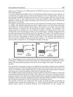
as the one developed for ceramic materials (Ref 49) depicted in Fig. 9, help illustrate the relative contribution of various
failure modes as a function of temperature and stress.
Fig. 9 Fracture mechanism map for hot-
pressed silicon nitride flexure bars. Fracture mechanism maps help
illustrate the relative contribution of various failure modes as a function of temperature and stress. Source:
Ref
49
In addition to the determination of the Weibull shape and scale parameters discussed previously, analysis of time-
dependent reliability in brittle materials necessitates accurate stress field information, as well as evaluation of distinct
parameters reflecting material, microstructural, and/or environmental conditions. Predicted lifetime reliability of brittle
material components depends on Weibull and fatigue parameters estimated from rupture data obtained from widely used
tests involving flexural or tensile specimens. Fatigue parameter estimates are obtained from naturally flawed specimens
ruptured under static (creep), cyclic, or dynamic (constant stress rate) loading. For other specimen geometries, a finite
element model of the specimen is also required when estimating these parameters. For a more detailed discussion of time-
dependent parameter estimation, the reader is directed to the CARES/Life (CARES/Life Prediction Program) Users and
Programmers Manual (Ref 50). This information can then be combined with stochastic modeling approaches and
incorporated into integrated design algorithms (computer software) in a manner similar to that presented previously for
time-independent models. The theoretical concepts upon which these time-dependent algorithms have been constructed
and the effects of time-dependent mechanisms, most notably subcritical crack growth and creep, are addressed in the
remaining sections of this article.
Although it is not discussed in detail here, one approach to improve the confidence in component reliability predictions is
to subject the component to proof testing prior to placing it in service. Ideally, the boundary conditions applied to a
component under proof testing simulate those conditions the component would be subjected to in service, and the proof
test loads are appropriately greater in magnitude over a fixed time interval. This form of testing eliminates the weakest
components and, thus, truncates the tail of the strength distribution curve. After proof testing, surviving components can
be placed in service with greater confidence in their integrity and a predictable minimum service life.
Need for Correct Stress State
With increasing use of brittle materials in high-temperature structural applications, the need arises to accurately predict
thermomechanical behavior. Most current analytical methods for both subcritical crack growth and creep models use
elastic stress fields in predicting the time-dependent reliability response of components subjected to elevated service
temperatures. Inelastic response at high temperature has been well documented in the materials science literature for these
material systems, but this issue has been ignored by the engineering design community. However, the authors wish to
emphasize that accurate predictions of time-dependent reliability demand accurate stress-field information. From a design
engineer's perspective, it is imperative that the inaccuracies of making time-dependent reliability predictions based on
elastic stress fields are taken into consideration. This section addresses this issue by presenting a recent formulation of a
viscoplastic constitutive theory to model the inelastic deformation behavior of brittle materials at high temperatures.
Early work in the field of metal plasticity indicated that inelastic deformations are essentially unaffected by hydrostatic
stress. This is not the case for brittle (e.g., ceramic-based) material systems, unless the material is fully dense. The theory
presented here allows for fully dense material behavior as a limiting case. In addition, as pointed out in Ref 51, these
materials exhibit different time-dependent behavior in tension and compression. Thus, inelastic deformation models for
these materials must be constructed in a manner that admits sensitivity to hydrostatic stress and differing behavior in
tension and compression.
A number of constitutive theories for materials that exhibit sensitivity to the hydrostatic component of stress have been
proposed that characterize deformation using time-independent classical plasticity as a foundation. Corapcioglu and Uz
(Ref 52) reviewed several of these theories by focusing on the proposed form of the individual yield function. The review
includes the works of Kuhn and Downey (Ref 53), Shima and Oyane (Ref 54), and Green (Ref 55). Not included is the
work by Gurson (Ref 56), who not only developed a yield criteria and flow rule, but also discussed the role of void
nucleation. Subsequent work by Mear and Hutchinson (Ref 57) extended Gurson's work to include kinematic hardening
of the yield surfaces.
Although the previously mentioned theories admit a dependence on the hydrostatic component of stress, none of these
theories allows different behavior in tension and compression. In addition, the aforementioned theories are somewhat
lacking in that they are unable to capture creep, relaxation, and rate-sensitive phenomena exhibited by brittle materials at
high temperature. Noted exceptions are the recent work by Ding et al. (Ref 58) and the work by White and Hazime (Ref
59). Another exception is an article by Liu et al. (Ref 60), which is an extension of the work presented by Ding and
coworkers. As these authors point out, when subjected to elevated service temperatures, brittle materials exhibit complex
thermomechanical behavior that is inherently time dependent and hereditary in the sense that current behavior depends
not only on current conditions, but also on thermomechanical history.
The macroscopic continuum theory formulated in the remainder of this section captures these time-dependent phenomena
by developing an extension of a J
2
plasticity model first proposed by Robinson (Ref 61) and later extended to sintered
powder metals by Duffy (Ref 62). Although the viscoplastic model presented by Duffy (Ref 62) admitted a sensitivity to
hydrostatic stress, it did not allow for different material behavior in tension and compression.
Willam and Warnke (Ref 63) proposed a yield criterion for concrete that admits a dependence on the hydrostatic
component of stress and explicitly allows different material responses in tension and compression. Several formulations
of their model exist, that is, a three-parameter formulation and a five-parameter formulation. For simplicity, the overview
of the multiaxial derivation of the viscoplastic constitutive model presented here builds on the three-parameter
formulation. The attending geometrical implications have been presented elsewhere (Ref 64, 65). A quantitative
assessment has yet to be conducted because the material constants have not been suitably characterized for a specific
material. The quantitative assessment could easily dovetail with the nascent efforts of White and coworkers (Ref 59).
The complete theory is derivable from a scalar dissipative potential function identified here as . Under isothermal
conditions, this function is dependent on the applied stress
ij
and internal state variable
ij
:
= (
ij
,
ij
)
(Eq 53)
The stress dependence for a J
2
plasticity model or a J
2
viscoplasticity model is usually stipulated in terms of the deviatoric
components of the applied stress, S
ij
=
ij
- ( )
kk ij
, and a deviatoric state variable, a
ij
=
ij
- ( )
kk ij
. For the
viscoplasticity model presented here, these deviatoric tensors are incorporated along with the effective stress,
ij
=
ij
-
ij
, and an effective deviatoric stress, identified as
ij
= S
ij
- a
ij
. Both tensors, that is,
ij
and
ij
, are utilized for
notational convenience.
The potential nature of is exhibited by the manner in which the flow and evolutionary laws are derived. The flow law is
derived from by taking the partial derivative with respect to the applied stress:
(Eq 54)
The adoption of a flow potential and the concept of normality, as expressed in Eq 54, were introduced by Rice (Ref 66).
In his work, the above relationship was established using thermodynamic arguments. The authors wish to point out that
Eq 54 holds for each individual inelastic state.
The evolutionary law is similarly derived from the flow potential. The rate of change of the internal stress is expressed as:
(Eq 55)
where h is a scalar function of the inelastic state variable (i.e., the internal stress) only. Using arguments similar to Rice's,
Ponter, and Leckie (Ref 67) have demonstrated the appropriateness of this type of evolutionary law.
To give the flow potential a specific form, the following integral format proposed by Robinson (Ref 61) is adopted:
(Eq 56)
where , R, H, and K are material constants. In this formulation is a viscosity constant, H is a hardening constant, n and
m are unitless exponents, and R is associated with recovery. The octahedral threshold shear stress K appearing in Eq 56 is
generally considered a scalar state variable that accounts for isotropic hardening (or softening). However, because
isotropic hardening is often negligible at high homologous temperatures (T/T
m
0.5), to a first approximation K is taken
to be a constant for metals. This assumption is adopted in the present work for brittle materials. The reader is directed to
Ref 68 for specific details regarding the experimental test matrix needed to characterize these parameters.
The dependence on the effective stress
ij
and the deviatoric internal stress a
ij
is introduced through the scalar functions
F = F (
ij
,
ij
) and G = G (a
ij
,
ij
). Inclusion of
ij
and
ij
will account for sensitivity to hydrostatic stress. The concept
of a threshold function was introduced by Bingham (Ref 69) and later generalized by Hohenemser and Prager (Ref 70).
Correspondingly, F is referred to as a Bingham-Prager threshold function. Inelastic deformation occurs only for those
stress states where F (
ij
,
ij
) > 0.
For frame indifference, the scalar functions F and G (and hence ) must be form invariant under all proper orthogonal
transformations. This condition is ensured if the functions depend only on the principal invariants of
ij
, a
ij
ij
, and
ij
;
that is, F = F (
1
,
2
,
3
), where
1
=
ii
,
2
= ( )
ij
ij
,
3
= ( )
ij
jk
ki
, and G = G (
1
,
2
,
3
), where I
1
=
a
ii
, J
2
= ( )a
ij
a
ij
, J
3
= ( ) a
ij
a
jk
a
ki
. These scalar quantities are elements of what is known in invariant theory as an integrity
basis for the functions F and G.
A three-parameter flow criterion proposed by Willam and Warnke (Ref 63) serves as the Bingham-Prager threshold
function, F. The William-Warnke criterion uses the previously mentioned stress invariants to define the functional
dependence on the Cauchy stress (
ij
) and internal state variable (
ij
). In general, this flow criterion can be constructed
from the following general polynomial:
(Eq 57)
where
c
is the uniaxial threshold flow stress in compression and B is a constant determined by considering
homogeneously stressed elements in the virgin inelastic state
ij
= 0.
Note that a threshold flow stress is similar in nature to a yield stress in classical plasticity. In addition, is a function
dependent on the invariant J
3
and other threshold stress parameters that are defined momentarily. The specific details in
deriving the final form of the function F can be found in Willam and Warnke (Ref 63), and this final formulation is stated
here as:
(Eq 58)
for brevity. The invariant
1
in Eq 58 admits a sensitivity to hydrostatic stress. The function F is implicitly dependent on
3
through the function r( ), where the angle of similitude, , is defined by the expression:
(Eq 59)
The invariant
3
accounts for different behavior in tension and compression, because this invariant changes sign when
the direction of a stress component is reversed. The parameter characterizes the tensile hydrostatic threshold flow stress.
For the Willam-Warnke three-parameter formulation, the model parameters include
t
, the tensile uniaxial threshold
stress,
c
, the compressive uniaxial threshold stress, and
bc
, the equal biaxial compressive threshold stress.
A similar functional form is adopted for the scalar state function G. However, this formulation assumes a threshold does
not exist for the scalar function G and follows the framework of previously proposed constitutive models based on
Robinson's viscoplastic law (Ref 61).
Employing the chain rule for differentiation and evaluating the partial derivative of with respect to
ij
, and then with
respect to
ij
, as indicated in Eq 54 and 55, yields the flow law and the evolutionary law, respectively. These expressions
are dependent on the principal invariants (i.e.,
1
,
2
,
3
,
1
,
2
, and
3
) the three Willam-Warnke threshold
parameters (i.e.,
t
,
c
, and
bc
), and the flow potential parameters utilized in Eq 56 (i.e., , R, H, K, n, and m). These
expressions constitute a multiaxial statement of a constitutive theory for isotropic materials and serve as an inelastic
deformation model for ceramic materials.
The overview presented in this section is intended to provide a qualitative assessment of the capabilities of this
viscoplastic model in capturing the complex thermomechanical behavior exhibited by brittle materials at elevated service
temperatures. Constitutive equations for the flow law (strain rate) and evolutionary law have been formulated based on a
threshold function that exhibits a sensitivity to hydrostatic stress and allows different behavior in tension and
compression. Furthermore, inelastic deformation is treated as inherently time dependent. A rate of inelastic strain is
associated with every state of stress. As a result, creep, stress relaxation, and rate sensitivity are phenomena resulting
from applied boundary conditions and are not treated separately in an ad hoc fashion. Incorporating this model into a
nonlinear finite element code would provide a tool for the design engineer to simulate numerically the inherently time-
dependent and hereditary phenomena exhibited by these materials in service.
Life Prediction Reliability Models
Using a time-dependent reliability model such as those discussed in the following section, and the results obtained from a
finite element analysis, the life of a component with complex geometry and loading can be predicted. This life is
interpreted as the reliability of a component as a function of time. When the component reliability falls below a
predetermined value, the associated point in time at which this occurs is assigned the life of the component. This design
methodology presented herein combines the statistical nature of strength-controlling flaws with the mechanics of crack
growth to allow for multiaxial stress states, concurrent (simultaneously occurring) flaw populations, and scaling effects.
With this type of integrated design tool, a design engineer can make appropriate design changes until an acceptable time
to failure has been reached. In the sections that follow, only creep rupture and fatigue failure mechanisms are discussed.
Although models that account for subcritical crack growth and creep rupture are presented, the reader is cautioned that
currently available creep models for advanced ceramics have limited applicability because of the phenomenological
nature of the models. There is a considerable need to develop models incorporating both the ceramic material behavior
and microstructural events.
Subcritical Crack Growth. A wide variety of brittle materials, including ceramics and glasses, exhibit the
phenomenon of delayed fracture or fatigue. Under the application of a loading function of magnitude smaller than that
which induces short-term failure, there is a regime where subcritical crack growth occurs and this can lead to eventual
component failure in service. Subcritical crack growth is a complex process involving a combination of simultaneous and
synergistic failure mechanisms. These can be grouped into two categories: (1) crack growth due to corrosion and (2) crack
growth due to mechanical effects arising from cyclic loading. Stress corrosion reflects a stress-dependent chemical
interaction between the material and its environment.Water, for example, has a pronounced deleterious effect on the
strength of glass and alumina. In addition, higher temperatures also tend to accelerate this process. Mechanically induced
cyclic fatigue is dependent only on the number of load cycles and not on the duration of the cycle. This phenomenon can
be caused by a variety of effects, such as debris wedging or the degradation of bridging ligaments, but essentially it is
based on the accumulation of some type of irreversible damage that tends to enhance crack growth. Service environment,
material composition, and material microstructure determine if a brittle material will display some combination of these
fatigue mechanisms.
Lifetime reliability analysis accounting for SCG under cyclic and/or sustained loads is essential for the safe and efficient
utilization of brittle materials in structural design. Because of the complex nature of SCG, models that have been
developed tend to be semiempirical and approximate the behavior of SCG phenomenologically. Theoretical and
experimental work in this area has demonstrated that lifetime failure characteristics can be described by consideration of
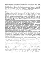
the crack growth rate versus the stress intensity factor (or the range in the stress intensity factor). This is graphically
depicted (see Fig. 10) as the logarithm of crack growth rate versus the logarithm of the mode I stress intensity factor.
Curves of experimental data show three distinct regimes or regions of growth. The first region (denoted by I in Fig. 10)
indicates threshold behavior of the crack, where below a certain value of stress intensity the crack growth is zero. The
second region (denoted by II in Fig. 10) shows an approximately linear relationship of stable crack growth.The third
region (denoted by III in Fig. 10) indicates unstable crack growth as the materials critical stress intensity factor is
approached. For the stress-corrosion failure mechanism, these curves are material and environment sensitive. This SCG
model, using conventional fracture mechanics relationships, satisfactorily describes the failure mechanisms in materials
where at high temperatures, plastic deformations and creep behave in a linear viscoelastic manner (Ref 71). In general, at
high temperatures and low levels of stress, failure is best described by creep rupture, which generates new cracks (Ref
72). The creep rupture process is discussed further in the next section.
Fig. 10 Schematic illustrating three different regimes of crack growth
The most-often-cited models in the literature regarding SCG are based on power-law formulations.Other theories, most
notably Wiederhorn's (Ref 73), have not achieved such widespread usage, although they may also have a reasonable
physical foundation. Power-law formulations are used to model both the stress-corrosion phenomenon and the cyclic
fatigue phenomenon.This modeling flexibility, coupled with their widespread acceptance, make these formulations the
most attractive candidates to incorporate into a design methodology. A power-law formulation is obtained by assuming
the second crack growth region is linear and that it dominates the other regions. Three power-law formulations are useful
for modeling brittle materials: the power law, the Paris law, and the Walker equation. The power law (Ref 71, 74)
describes the crack velocity as a function of the stress intensity factor and implies that the crack growth is due to stress
corrosion. For cyclic fatigue, either the Paris law (Ref 75) or Walker's (Ref 76, 77) modified formulation of the Paris law
is used to model the SCG. The Paris law describes the crack growth per load cycle as a function of the range in the stress
intensity factor. The Walker equation relates the crack growth per load cycle to both the range in the crack tip stress
intensity factor and the maximum applied crack tip stress intensity factor. It is useful for predicting the effect of the R-
ratio (the ratio of the minimum cyclic stress to the maximum cyclic stress) on the material strength degradation.
Expressions for time-dependent reliability are usually formulated based on the mode I equivalent stress distribution
transformed to its equivalent stress distribution at time t = 0. Investigations of mode I crack extension (Ref 78) have
resulted in the following relationship for the equivalent mode I stress intensity factor:
K
Ieq
( , t) =
Ieq
( , t) Y
(Eq 60)
where
Ieq
( , t) is the equivalent mode I stress on the crack, Y is a function of crack geometry, a ( , t) is the
appropriate crack length, and represents a spatial location within the body and the orientation of the crack. In some
models (such as the phenomenological Weibull NSA and the PIA models), represents a location only. Y is a function of
crack geometry; however, herein it is assumed constant with subcritical crack growth. Crack growth as a function of the
equivalent mode I stress intensity factor is assumed to follow a power-law relationship:
(Eq 61)
where A and N are material/environmental constants.The transformation of the equivalent stress distribution at the time of
failure, t = t
f
, to its critical effective stress distribution at time t = 0 is expressed (Ref 79, 80):
(Eq 62)
where
(Eq 63)
is a material/environmental fatigue parameter, K
Ic
is the critical stress intensity factor, and
Ieq
( , t
f
) is the equivalent
stress distribution in the component at time t = t
f
. The dimensionless fatigue parameter N is independent of fracture
criterion. B is adjusted to satisfy the requirement that for a uniaxial stress state, all models produce the same probability of
failure. The parameter B has units of stress
2
× time.
Because SCG assumes flaws exist in a material, the weakest-link statistical theories discussed previously are required to
predict the time-dependent lifetime reliability for brittle materials. An SCG model (e.g., the previously discussed power
law, Paris law, or Walker equation) is combined with either the two- or three-parameter Weibull cumulative distribution
function to characterize the component failure probability as a function of service lifetime. The effects of multiaxial
stresses are considered by using the PIA model, the Weibull NSA method, or the Batdorf theory. These multiaxial
reliability expressions were outlined in the previous section on time-independent reliability analysis models, and, for
brevity, are not repeated here. The reader is directed to see the previous section or, for more complete details, to consult
Ref 50.
Creep Rupture. For brittle materials, the term creep can infer two different issues. The first relates to catastrophic
failure of a component from a defect that has been nucleated and propagates to critical size. This is known as creep
rupture to the design engineer. Here, it is assumed that failure does not occur from a defect in the original flaw
population. Unlike SCG, which is assumed to begin at preexisting flaws in a component and continue until the crack
reaches a critical length, creep rupture typically entails the nucleation, growth, and coalescence of voids which eventually
form macrocracks, which then propagate to failure. The second issue related to creep reflects back on SCG as well as
creep rupture, that is, creep deformation. This section focuses on the former, while the latter (i.e., creep deformation) is
discussed in a previous section.
Currently, most approaches to predict brittle material component lifetime due to creep rupture employ deterministic
methodologies. Stochastic methodologies for predicting creep life in brittle material components have not reached a level
of maturity comparable to those developed for predicting fast-fracture and SCG reliability. One such theory is based on
the premise that both creep and SCG failure modes act simultaneously (Ref 81). Another alternative method for
characterizing creep rupture in ceramics was developed by Duffy and Gyekenyesi, (Ref 82), who developed a time-
dependent reliability model that integrates continuum damage mechanics principles and Weibull analysis. This particular
approach assumes that the failure processes for SCG and creep are distinct and separable mechanisms.
The remainder of this section outlines this approach, highlighting creep rupture with the intent to provide the design
engineer with a method to determine an allowable stress for a given component lifetime and reliability. This is
accomplished by coupling Weibull theory with the principles of continuum damage mechanics, which was originally
developed by Kachanov (Ref 83) to account for tertiary creep and creep fracture of ductile metal alloys.
Ideally, any theory that predicts the behavior of a material should incorporate parameters that are relevant to its
microstructure (grain size, void spacing, etc.). However, this would require a determination of volume-averaged effects of
microstructural phenomena reflecting nucleation, growth, and coalescence of microdefects that in many instances interact.
This approach is difficult even under strongly simplifying assumptions. In this respect, Leckie (Ref 84) points out that the
difference between the materials scientists and the engineer is one of scale. He notes the materials scientist is interested in
mechanisms of deformation and failure at the microstructural level and the engineer focuses on these issues at the
component level. Thus, the former designs the material and the latter designs the component. Here, the engineer's
viewpoint is adopted, and readers should note from the outset that continuum damage mechanics does not focus attention
on microstructural events, yet this logical first approach does provide a practical model, which macroscopically captures
the changes induced by the evolution of voids and defects.
This method uses a continuum-damage approach where a continuity function, , is coupled with Weibull theory to render
a time-dependent damage model for ceramic materials. The continuity function is given by the expression:
= [1 - b(
0
)
m
(m + 1)t]
(1/(m+1))
(Eq 64)
where b and m are material constants,
0
is the applied uniaxial stress on a unit volume, and t is time. From this, an
expression for a time to failure, t
f
, can be obtained by noting that when t = t
f
, = 0. This results in the following:
(Eq 65)
which leads to the simplification of as follows:
= [1 - (t/t
f
)]
(1/(m+1))
(Eq 66)
The above equations are then coupled with an expression for reliability to develop the time-dependent model. The
expression for reliability for a uniaxial specimen is:
R = exp [ -V ( / ) ]
(Eq 67)
where V is the volume of the specimen, is the Weibull shape parameter, and is the Weibull scale parameter.
Incorporating the continuity function into the reliability equation and assuming a unit volume yields:
R = exp [ -(
0
/ ) ]
(Eq 68)
Substituting for in terms of the time to failure results in the time-dependent expression for reliability:
(Eq 69)
This model has been presented in a qualitative fashion, intending to provide the design engineer with a reliability theory
that incorporates the expected lifetime of a brittle material component undergoing damage in the creep rupture regime.
The predictive capability of this approach depends on how well the macroscopic state variable captures the growth of
grain-boundary microdefects. Finally, note that the kinetics of damage also depend significantly on the direction of the
applied stress. In the development described previously, it was expedient from a theoretical and computational standpoint
to use a scalar state variable for damage because only uniaxial loading conditions were considered. The incorporation of a
continuum-damage approach within a multiaxial Weibull analysis necessitates the description of oriented damage by a
second-order tensor.
Life-Prediction Reliability Algorithms
The NASA-developed computer program CARES/Life (Ceramics Analysis and Reliability Evaluation of Structures/Life-
Prediction program) and the AlliedSignal algorithm ERICA have the capability to evaluate the time-dependent reliability
of monolithic ceramic components subjected to thermomechanical and/or proof test loading. The reader is directed to Ref
39 and Ref 40 for a detailed discussion of the life-prediction capabilities of the ERICA algorithm. The CARES/Life
program is an extension of the previously discussed CARES program, which predicted the fast-fracture (time-
independent) reliability of monolithic ceramic components. CARES/Life retains all of the fast-fracture capabilities of the
CARES program and also includes the ability to perform time-dependent reliability analysis due to SCG. CARES/Life
accounts for the phenomenon of SCG by utilizing the power law, Paris law, or Walker equation. The Weibull cumulative
distribution function is used to characterize the variation in component strength. The probabilistic nature of material
strength and the effects of multiaxial stresses are modeled using either the PIA, the Weibull NSA, or the Batdorf theory.
Parameter estimation routines are available for obtaining inert strength and fatigue parameters from rupture strength data
of naturally flawed specimens loaded in static, dynamic, or cyclic fatigue. Fatigue parameters can be calculated using
either the median value technique (Ref 85), a least squares regression technique, or a median deviation regression method
that is somewhat similar to trivariant regression (Ref 85). In addition, CARES/Life can predict the effect of proof testing
on component service probability of failure. Creep and material healing mechanisms are not addressed in the CARES/Life
code.
Life-Prediction Design Examples
Once again, because of the proprietary nature of the ERICA algorithm, the life-prediction examples presented in this
section are all based on design applications where the NASA CARES/Life algorithm was utilized. Either algorithm should
predict the same results cited here. However, at this point in time comparative studies utilizing both algorithms for the
same analysis are not available in the open literature. The primary thrust behind CARES/Life is the support and
development of advanced heat engines and related ceramics technology infrastructure. This U.S. Department of Energy
(DOE), and Oak Ridge National Laboratory (ORNL) have several ongoing programs such as the Advanced Turbine
Technology Applications Project (ATTAP) (Ref 48, 86) for automotive gas turbine development, the Heavy Duty
Transport Program for low-heat-rejection heavy-duty diesel engine development, and the Ceramic Stationary Gas Turbine
(CSGT) program for electric power cogeneration. Both CARES/Life and the previously discussed CARES program are
used in these projects to design stationary and rotating equipment, including turbine rotors, vanes, scrolls, combustors,
insulating rings, and seals. These programs are also integrated with the DOE/ORNL Ceramic Technology Project (CTP)
(Ref 87) characterization and life prediction efforts (Ref 88, 89).
The CARES/Life program has been used to design hot-section turbine parts for the CSGT development program (Ref 90)
sponsored by the DOE Office of Industrial Technology. This project seeks to replace metallic hot-section parts with
uncooled ceramic components in an existing design for a natural-gas-fired industrial turbine engine operating at a turbine
rotor inlet temperature of 1120 °C (2048 °F). At least one stage of blades (Fig. 11) and vanes, as well as the combustor
liner, will be replaced with ceramic parts. Ultimately, demonstration of the technology will be proved with a 4000 h
engine field test.
Fig. 11 Stress contour plot of first-stage silicon nitride turbine rotor blade for a natural-gas-
fired industrial
turbine engine for cogeneration. The blade is rotating at 14,950 rpm. Courtesy of Solar Turbines Inc.
Ceramic pistons for a constant-speed drive are being developed. Constant-speed drives are used to convert variable engine
speed to a constant output speed for aircraft electrical generators. The calculated probability of failure of the piston is less
than 0.2 × 10
-8
under the most severe limit-load condition. This program is sponsored by the U.S. Navy and ARPA
(Advanced Research Projects Agency, formerly DARPA, Defense Advanced Research Projects Agency). As depicted in
Fig. 12, ceramic components have been designed for a number of other applications, most notably for aircraft auxiliary
power units.
Fig. 12
(a) Ceramic turbine wheel and nozzle for advanced auxiliary power unit. (b) Ceramic components for
small expendable turbojet. Courtesy of Sundstrand Aerospace Corporation
Glass components behave in a similar manner as ceramics and must be designed using reliability evaluation techniques.
The possibility of alkali strontium silicate glass CRTs spontaneously imploding has been analyzed (Ref 91). Cathode ray
tubes are under a constant static load due to the pressure forces placed on the outside of the evacuated tube. A 68 cm (27
in.) diagonal tube was analyzed with and without an implosion protection band. The implosion protection band reduces
the overall stresses in the tube and, in the event of an implosion, also contains the glass particles within the enclosure.
Stress analysis (Fig. 13) showed compressive stresses on the front face and tensile stresses on the sides of the tube. The
implosion band reduced the maximum principal stress by 20%. Reliability analysis with CARES/Life showed that the
implosion protection band significantly reduced the probability of failure to about 5 × 10
-5
.
Fig. 13
Stress plot of an evacuated 68 cm (27 in.) diagonal CRT. The probability of failure calculated with
CARES/Life was less than 5.0 × 10
-3
. Courtesy of Philips Display Components Company
The structural integrity of a silicon carbide convection air heater for use in an advanced power-generation system has
been assessed by ORNL and the NASA Lewis Research Center. The design used a finned tube arrangement 1.8 m (70.9
in.) in length with 2.5 cm (1 in.) diam tubes. Incoming air was to be heated from 390 to 700 °C (734 to 1292 °F). The hot
gas flow across the tubes was at 980 °C (1796 °F). Heat transfer and stress analyses revealed that maximum stress
gradients across the tube wall nearest the incoming air would be the most likely source of failure.
Probabilistic design techniques are being applied to dental ceramic crowns, as illustrated in Fig. 14. Frequent failure of
some ceramic crowns (e.g., 35% failure of molar crowns after three years), which occurs because of residual and
functional stresses, necessitates design modifications and improvement of these restorations. Thermal tempering
treatment is being investigated as a means of introducing compressive stresses on the surface of dental ceramics to
improve the resistance to failure (Ref 92). Evaluation of the risk of material failure must be considered not only for the
service environment, but also from the tempering process.
Fig. 14 Stress contour plot of ceramic dental crown, resulting from a 600 N biting force.
Courtesy of University
of Florida College of Dentistry
References cited in this section
39.
J.C. Cuccio, P. Brehm, H.T. Fang, J. Hartman, W. Meade, M.N
. Menon, A. Peralta, J.Z. Song, T.
Strangman, J. Wade, J. Wimmer, and D.C. Wu, "Life Prediction Methodology for Ceramic Components of
Advanced Heat Engines, Phase I," ORNL/Sub/89-
SC674/1/V1, Vol 1, Final Report, Oak Ridge National
Laboratory, March 1995
40.
J.C. Cuccio, P. Brehm, H.T. Fang, J. Hartman, W. Meade, M.N. Menon, A. Peralta, J.Z. Song, T.
Strangman, J. Wade, J. Wimmer, and D.C. Wu, "Life Prediction Methodology for Ceramic Components of
Advanced Heat Engines, Phase I," ORNL/Sub/89-SC674/1/V2, Vol
2, Final Report, Oak Ridge National
Laboratory, March 1995
48.
J.R. Smyth, R.E. Morey, and R.W. Schultz, "Ceramic Gas Turbine Technology Development and
Applications," Paper 93-GT-361, presented at the International Gas Turbine and Aeroengine Congress an
d
Exposition (Cincinnati, OH), 24-27 May 1993
49.
G.D. Quinn, Fracture Mechanism Maps for Advanced Structural Ceramics: Part 1; Methodology and Hot-
Pressed Silicon Nitride Results, J. Mater. Sci., Vol 25, 1990, p 4361-4376
50.
N.N. Nemeth, L.M. Powers, L.A. Janosik, and J.P. Gyekenyesi, "CARES/Life
Prediction Program
(CARES/Life) Users and Programmers Manual," TM-106316, to be published
51.
T
J. Chuang, and S.F. Duffy, A Methodology to Predict Creep Life for Advanced Ceramics Using
Continuum Damage Mechanics, Life Prediction Methodologies and Data for Ceramic Materials,
STP 1201,
C.R. Brinkman and S.F. Duffy, Ed., ASTM, 1994, p 207-227
52.
Y. Corapcioglu and T. Uz, Constitutive Equations for Plastic Deformation of Porous Materials,
Powder
Technol., Vol 21, 1978, p 269-274
53.
H.A. Kuhn and C.L. Downey, Deformation Characteristics and Plasticity Theory of Sintered Powder
Metals, Int. J. Powder Metall., Vol 7, 1971, p 15-25
54.
S. Shima and M. Oyane, Plasticity Theory for Porous Metals, Int. J. Mech. Sci., Vol 18, 1976, p 285
55.
R.J. Green, A Plasticity Theory for Porous Solids, Int. J. Mech. Sci., Vol 14, 1972, p 215
56.
A.L. Gurson, Continuum Theory of Ductile Rupture by Void Nucleation and Growth: Part I
Yield Criteria
and Flow Rules for Porous Ductile Media, J. Eng. Mater. Technol., Vol 99, 1977, p 2-15
57.
M.E. Mear and J.W. Hutchinson, Influence of Yield Surface Curvature on Flow Local
ization in Dilatant
Plasticity, Mech. Mater., Vol 4, 1985, p 395-407
58.
J
L. Ding, K.C. Liu, and C.R. Brinkman, A Comparative Study of Existing and Newly Proposed Models
for Creep Deformation and Life Prediction of Si3N4, Life Prediction Methodologies a
nd Data for Ceramic
Materials, STP 1201, C.R. Brinkman and S.F. Duffy, Ed., ASTM, 1994, p 62-83
59.
C.S. White, and R.M. Hazime, Internal Variable Modeling of the Creep of Monolithic Ceramics,
proceedings of the 11th Biennial Conference on Reliability, Stress Analysis, and Failure Prevention,
O.
Jadaan, Ed., American Society of Mechanical Engineers, 1995
60.
K.C. Liu, C.R. Brinkman, J L. Ding, and S.Liu, Predictions of Tensile Behavior and Strengths of Si
3
N
4
Ceramic at High Temperatures Based on a Viscoplastic Model, ASME Trans., 95-GT-388, 1995
61.
D.N. Robinson, "A Unified Creep-
Plasticity Model for Structural Metals at High Temperature," ORNL/TM
5969, Oak Ridge National Laboratory, 1978
62.
S.F. Duffy, A Unified Inelastic Constitutive Theory for Sintered Powder Metals, Mech. Mater.,
Vol 7, 1988,
p 245-254
63.
K.J. Willam and E.P. Warnke, Constitutive Model for the Triaxial Behaviour of Concrete, Int.
Assoc.
Bridge Struct. Eng. Proc., Vol 19, 1975, p 1-30
64.
L.A. Janosik and S.F. Duffy, A Viscoplastic Constitutive Theory for Monolithic Ceramic Materials
I,
paper 15, Proceedings of the Physics and Process Modeling (PPM) and Other Propulsion R&T Conference,
Vol I, Materials Processing, Characterization, and Modeling; Lifing Models, CP-
10193, National
Aeronautics and Space Administration, 1997
65.
L.A. Janosik and S.F. Duffy, A Viscoplastic Constitutive Theory for Monolithic Ceramics I, paper No. 96-
GT-
368, International Gas Turbine Congress, Exposition, and Users' Symposium (Birmingham, UK),
American Society of Mechanical Engineers, 10-13 June 1996
66.
J.R. Rice, On the Structure of Stress-Strain Relations for Time-Dependent Plastic Deformation in Metals,
J.
Appl. Mech., Vol 37, 1970, p 728
67.
A.R.S. Ponter and F.A. Leckie, Constitutive Relationships for Time-Dependent Deformation of Metals,
J.
Eng. Mater. Technol. (Trans. ASME), Vol 98, 1976
68.
L.A. Janosik, "A Unified Viscoplastic Constitutive Theory for Monolithic Ceramics," Master's thesis,
Cleveland State University, Cleveland, OH, 1997, to be published
69.
E.C. Bingham, Fluidity and Plasticity, McGraw-Hill, 1922
70.
K. Hohenemser and W. Prager, Ueber die Ansaetze der Mechanik Isotroper Kontinua,
Z. Angewandte
Mathemat. Mech., Vol 12, 1932 (in German)
71.
A.G. Evans and S.M. Wiederhorn, Cra
ck Propagation and Failure Prediction in Silicon Nitride at Elevated
Temperatures, J. Mater. Sci., Vol 9, 1974, p 270-278
72.
S.M. Wiederhorn and E.R. Fuller, Jr., Structural Reliability of Ceramic Materials, Mater. Sci. Eng.,
Vol 71,
1985, p 169-186
73.
S.M. Wiederhorn, E.R. Fuller, and R. Thomson, Micromechanisms of Crack Growth in Ceramics and
Glasses in Corrosive Environments, Met. Sci., Aug-Sept 1980, p 450-458
74.
S.M. Wiederhorn, Fracture Mechanics of Ceramics, R.C. Bradt, D.P. Hasselman, and F.F.
Lange, Ed.,
Plenum, 1974, p 613-646
75.
P. Paris and F. Erdogan, A Critical Analysis of Crack Propagation Laws, J. Basic Eng.,
Vol 85, 1963, p
528-534
76.
K. Walker, The Effect of Stress Ratio During Crack Propagation and Fatigue for 2024-T3 and 7075-
T6
Aluminum, Effects of Environment and Complex Load History on Fatigue Life, STP 462, ASTM, 1970, p 1-
14
77.
R.H. Dauskardt, M.R. James, J.R. Porter, and R.O. Ritchie, Cyclic Fatigue Crack Growth in SiC-Whisker-
Reinforced Alumina Ceramic Composite: Long and Small Crack Behavior, J. Am. Ceram. Soc.,
Vol 75 (No.
4), 1992, p 759-771
78.
P.C. Paris and G.C. Sih, Stress Analysis of Cracks, Fracture Toughness Testing and Its Applications,
STP
381, ASTM, 1965, p 30-83
79.
T. Thiemeier, "Lebensdauervorhersage fun
Keramische Bauteile Unter Mehrachsiger Beanspruchung,"
Ph.D. dissertation, University of Karlesruhe, Germany, 1989 (in German)
80.
G. Sturmer, A. Schulz, and S. Wittig, "Lifetime Prediction for Ceramic Gas Turbine Components," Preprint
91-GT-96, American Society of Mechanical Engineers, 3-6 June 1991
81.
F. Lange, Interrelations Between Creep and Slow Crack Growth for Tensile Loading Conditions,
Int. J.
Fract., Vol 12, 1976, p 739-744
82.
S.F. Duffy and J.P. Gyekenyesi, "Time Dependent Reliability Model
Incorporating Continuum Damage
Mechanics for High-Temperature Ceramics," TM-
102046, National Aeronautics and Space Administration,
May 1989
83.
L.M. Kachanov, Time of the Rupture Process Under Creep Conditions, Izv.
Akad. Nauk. SSR, Otd Tekh.
Nauk, Vol 8, 1958, p 26
84.
F.A. Leckie, Advances in Creep Mechanics, Creep in Structures,
A.R.S. Ponter and D.R.Hayhurst, Ed.,
Springer-Verlag, 1981, p 13
85.
K. Jakus, D.C. Coyne, and J.E. Ritter, Analysis of Fatigue Data for Lifetime Predictions for Ceramic
Materials, J. Mater. Sci., Vol 13, 1978, p 2071-2080
86.
S.G. Berenyi, S.J. Hilpisch, and L.E. Groseclose, "Advanced Turbine Technology Applications Project
(ATTAP)," Proceedings of the Annual Automotive Technology Development Contractor's Coordination
Meeting (Dearborn, MI), 18-21 Oct 1993, SAE International
87.
D.R. Johnson and R.B. Schultz, "The Ceramic Technology Project: Ten Years of Progress," Paper 93-GT-
417, presented at the International Gas Turbine and Aeroengine Congress and Exposition (Cincinnati,
OH),
24-27 May 1993, American Society of Mechanical Engineers
88.
J. Cuccio, "Life Prediction Methodology for Ceramic Components of Advanced Heat Engines,"
Proceedings of the Annual Automotive Technology Development Contractor's Coordination Meeting
(Dearborn, MI), 18-21 Oct 1993
89.
P.K. Khandelwal, N.J. Provenzano, and W.E.Schneider, "Life Prediction Methodology for Ceramic
Components of Advanced Vehicular Engines," Proceedings of the Annual Automotive Technology
Development Contractor's Coordination Meeting (Dearborn, MI), 18-21 Oct 1993
90.
M. van Roode, W.D. Brentnall, P.F. Norton, and G.P. Pytanowski, "Ceramic Stationary Gas Turbine
Development," Paper 93-GT-
309, presented at the International Gas Turbine and Aeroengine Congress and
Exposition (Cincinnati, OH), 24-27 May 1993, American Society of Mechanical Engineers, 24-
27 May
1993
91.
A. Ghosh, C.Y. Cha, W. Bozek, and S. Vaidyanathan, Structural Reliability Analysis of CRTs,
Society for
Information Display International Symposium Digest of Technical Papers, Vol XXIII, 17-
22 May 1992,
Society of Information Display, Playa Del Ray, CA, p 508-510
92.
B. Hojjatie, Thermal Tempering of Dental Ceramics, Proceedings of the ANSYS Conference and Exhibition,
Vol 1, Swanson Analysis Systems Inc., Houston, PA, 1992, p I.73-I.91
Design with Brittle Materials
Stephen F. Duffy, Cleveland State University; Lesley A. Janosik, NASA Lewis Research Center
References
1. C.A. Johnson and W.T. Tucker, Advanced Statistical Concepts of Fracture in Brittle Materials, Vol
4,
Engineered Materials Handbook, ASM International, Ceramics and Glasses, 1991, p 708-715
2. W.A. Weibull, The Phenomenon of Rupture in Solids, Ing. Veten. Akad. Handl., No. 153, 1939
3. C.A. Johnson, Fracture Statistics of Multiple Flaw Populations, Fracture Mechanics of Ceramics,
Vol 5,
R.C. Bradt, A.G. Evans, D.P.H. Hasselman, and F.F. Lange, Ed., Plenum Press, 1983, p 365-386
4. W.A. Weibull, A Statistical Distribution Function of Wide Applicability, J. Appl. Mech.,
Vol 18 (No. 3),
Sept 1951, p 293-297
5. F.T. Pierce, "The Weakest Link" Theorems of the Strength of Long and of Composite Specimens,
Text.
Inst. J., Vol 17, 1926, p T355-T368
6. T.A. Kontorova, A Statistical Theory of Mechanical Strength, J. Tech. Phys. (USSR), Vol 10, 1940, p 886-
890
7. J.I. Frenkel and T.A. Kontorova, A Statistical Theory of the Brittle Strength of Real Crystals,
J. Phys.
USSR, Vol 7 (No. 3), 1943, p 108-114
8.
J. Hu, "Modeling Size Effects and Numerical Techniques in Structural Reliability Analysis," Master's
thesis, Cleveland State University, Cleveland, OH, 1994
9. T.T. Shih, An Evaluation of the Probabilistic Approach to Brittle Design, Eng. Fract. Mech.,
Vol 13 (No.
2), 1980, p 257-271
10.
S.F. Duffy and S.M. Arnold, Noninteractive Macroscopic Statistical Failu
re Theory for Whisker Reinforced
Ceramic Composites, J. Compos. Mater., Vol 24 (No. 3), 1990, p 293-308
11.
S.F. Duffy and J.M. Manderscheid, Noninteractive Macroscopic Reliability Model for Ceramic Matrix
Composites with Orthotropic Material Symmetry, J. Eng. Gas Turbines Power (Trans. ASME),
Vol 112
(No. 4), 1990, p 507-511
12.
N.N. Nemeth, J.M. Manderscheid, and J.P. Gyekenyesi, "Ceramics Analysis and Reliability Evaluation of
Structures (CARES) Users and Programmers Manual," TP-2916, National Aeronaut
ics and Space
Administration, 1990
13.
B. Gross and J.P. Gyekenyesi, Weibull Crack Density Coefficient for Polydimensional Stress States,
J. Am.
Ceram. Soc., Vol 72 (No. 3), 1989, p 506-507
14.
R.L. Barnett, C.L. Connors, P.C. Hermann, and J.R. Wingfield
, "Fracture of Brittle Materials under
Transient Mechanical and Thermal Loading," AFFDL-TR-66-
220, U.S. Air Force Flight Dynamics
Laboratory, March 1967
15.
A.M. Freudenthal, Statistical Approach to Brittle Fracture. Fracture, An Advanced Treatise, Mathem
atical
Fundamentals, Vol 2, H. Liebowitz, Ed., Academic Press, 1968, p 591-619
16.
J. Margetson, "A Statistical Theory of Brittle Failure for an Anisotropic Structure Subjected to a Multiaxial
Stress State," Paper 76-632, American Institute of Aeronautics and Astronautics, July 1976
17.
A. Paluszny and W. Wu, Probabilistic Aspects of Designing with Ceramics, J. Eng. Power,
Vol 99 (No. 4),
Oct 1977, p 617-630
18.
G.J. DeSalvo, "Theory and Structural Design Application of Weibull Statistics," WANL-TME-2688
,
Westinghouse Astronuclear Laboratory, 1970
19.
J.L. Wertz and P.W. Heitman, "Predicting the Reliability of Ceramic Turbine Components. Advanced Gas
Turbine Systems for Automobiles," SP-465, Society of Automotive Engineers, 1980, p 69-77
20.
W.H. Dukes, Handbook of Brittle Material Design Technology,
AGARDograph 152, AGARD, Paris,
France, 1971
21.
S.B. Batdorf, Fundamentals of the Statistical Theory of Fracture, Fracture Mechanics of Ceramics,
Vol 3,
R.C. Bradt, D.P.H. Hasselman, and F.F. Lange, Plenum Press, 1978, p 1-30
22.
S.B. Batdorf and J.G. Crose, A Statistical Theory for the Fracture of Brittle Structures Subjected to
Nonuniform Polyaxial Stresses, J. Appl. Mech., Vol 41 (No. 2), June 1974, p 459-464
23.
M. Giovan and G. Sines, Biaxial and Uniaxial Data for Statistical Comparison of a Ceramic's Strength,
J.
Am. Ceram. Soc., Vol 62 (No. 9), Sept 1979, p 510-515
24.
M.G. Stout and J.J. Petrovic, Multiaxial Loading Fracture of Al
2
O
3
Tubes: I, Experiments, J. Am.
Ceram.
Soc., Vol 67 (No. 1), Jan 1984, p 14-18
25.
J.J. Petrovic and M.G. Stout, Multiaxial Loading Fracture of Al
2
O
3
Tubes: II, Weibull Theory and Analysis,
J. Am. Ceram. Soc., Vol 67 (No. 1), Jan 1984, p 18-23
26.
K. Palaniswamy and W.G. Knauss, On the Problem of Crack Extension in Brit
tle Solids Under General
Loading, Mech. Today, Vol 4, 1978, p 87-148
27.
D.K. Shetty, Mixed-Mode Fracture Criteria for Reliability Analysis and Design with Structural Ceramics,
J.
Eng. Gas Turbines Power (Trans. ASME), Vol 109 (No. 3), July 1987, p 282-289
28.
S.F. Duffy, L.M. Powers, and A. Starlinger, Reliability Analysis of Structural Components Fabricated from
Ceramic Materials Using a Three-Parameter Weibull Distribution, J. Eng.
Gas Turbines Power (Trans.
ASME), Vol 115 (No. 1), Jan 1993, p 109-116
29.
G.D. Quinn, "Flexure Strength of Advanced Ceramics
A Round Robin Exercise," Materials Technology
Laboratory TR-89-62 (Available from the National Technical Information Service, AD-A212101, 1989)
30.
M.R. Foley, V.K. Pujari, L.C. Sales, and D.M. Trac
ey, Silicon Nitride Tensile Strength Data Base from
Ceramic Technology Program for Reliability Project,
Life Prediction Methodologies and Data for Ceramic
Materials, C.R. Brinkman and S.F. Duffy, Ed., ASTM, to be published
31.
L Y. Chao and D.K. Shetty, Reliability Analysis of Structural Ceramics Subjected to Biaxial Flexure,
J.
Am. Ceram. Soc., Vol 74 (No. 2), 1991, p 333-344
32.
S.F. Duffy, J.L. Palko, and J.P. Gyekenyesi, Structural Reliability of Laminated CMC Components,
J. Eng.
Gas Turbines and Power (Trans. ASME), Vol 115 (No. 1), 1993, p 103-108
33.
D.J. Thomas and R.C. Wetherhold, Reliability of Continuous Fiber Composite Laminates, Comput. Struct.,
Vol 17, 1991, p 277-293
34.
J.L. Palko, "An Interactive Reliability Model for Whisker-Toughened
Ceramics," Master's thesis, Cleveland
State University, Cleveland, OH, 1992
35.
J. Margetson and N.R. Cooper, Brittle Material Design Using Three Parameter Weibull Distributions,
Proceedings of the IUTAM Symposium on Probabilistic Methods in the Mechanics of Solids and Structures,
S. Eggwertz and N.C. Lind, Ed., Springer-Verlag, 1984, p 253-262
36.
S.S. Pai and J.P. Gyekenyesi, "Calculation of the Weibull Strength Parameters and Batdorf Flaw Density
Constants for Volume and Surface-Flaw-Induced Fracture in Ceramics," TM-
100890, National Aeronautics
and Space Administration, 1988
37.
J.P. Gyekenyesi and N.N. Nemeth, Surface Flaw Reliability Analysis of Ceramic Components with the
SCARE Finite Element Postprocessor Program, J. Eng. Gas Turbines Power (Trans. ASME),
Vol 109 (No.
3), July 1987, p 274-281
38.
J.P. Gyekenyesi, SCARE: A Postprocessor Program to MSC/NASTRAN for the Reliability Analysis of
Structural Ceramic Components, J. Eng. Gas Turbines Power (Trans. ASME),
Vol 108 (No. 3), July 1986, p
540-546
39.
J.C. Cuccio, P. Brehm, H.T. Fang, J. Hartman, W. Meade, M.N. Menon, A. Peralta, J.Z. Song, T.
Strangman, J. Wade, J. Wimmer, and D.C. Wu, "Life Prediction Methodology for Ceramic Components of
Advanced Heat Engines, Phase I," ORNL/Sub/89-SC674/1/V1,
Vol 1, Final Report, Oak Ridge National
Laboratory, March 1995
40.
J.C. Cuccio, P. Brehm, H.T. Fang, J. Hartman, W. Meade, M.N. Menon, A. Peralta, J.Z. Song, T.
Strangman, J. Wade, J. Wimmer, and D.C. Wu, "Life Prediction Methodology for Ceramic Componen
ts of
Advanced Heat Engines, Phase I," ORNL/Sub/89-
SC674/1/V2, Vol 2, Final Report, Oak Ridge National
Laboratory, March 1995
41.
C. Baker and D. Baker, Design Practices for Structural Ceramics in Automotive Turbocharger Wheels,
Ceramics and Glasses, Vol 4, Engineered Materials Handbook, ASM International, 1991, p 722-727
42.
C.J. Poplawsky, L. Lindberg, S. Robb, and J. Roundy, "Development of an Advanced Ceramic Turbine
Wheel for an Air Turbine Starter," Paper 921945, presented at Aerotech '92, Anaheim,
CA, Society of
Automotive Engineers, 5-8 Oct 1992
43.
J.H. Selverian, D. O'Neil, and S. Kang, Ceramic-to-Metal Joints: Part I-Joint Design, Am.
Ceram. Soc.
Bull., Vol 71 (No. 9), 1992, p 1403-1409
44.
J.H. Selverian and S. Kang, Ceramic-to-Metal Joints: Part II-Performance and Strength Prediction,
Am.
Ceram. Soc. Bull., Vol 71 (No. 10), 1992, p 1511-1520
45.
C.L. Snydar, "Reliability Analysis of a Monolithic Graphite Valve," presented at the 15th Annual
Conference on Composites, Materials, and Structures (Cocoa Beach, FL), American Ceramic Society, 1991
46.
J.A. Salem, J.M. Manderscheid, M.R. Freedman, and J.P. Gyekenyesi, "Reliability Analysis of a Structural
Ceramic Combustion Chamber," Paper 91-GT-
155, presented at the International Gas Turbine and
Aeroengine Congress and Exposition, Orlando, FL, 3-6 June 1991
47.
R.R. Wills and R.E. Southam, Ceramic Engine Valves, J. Am. Ceram. Soc., Vol 72 (No. 7), 1989, p 1261-
1264
48.
J.R. Smyth, R.E. Morey, and R.W. Schultz, "Ceramic Gas Turbine Technology Devel
opment and
Applications," Paper 93-GT-
361, presented at the International Gas Turbine and Aeroengine Congress and
Exposition (Cincinnati, OH), 24-27 May 1993
49.
G.D. Quinn, Fracture Mechanism Maps for Advanced Structural Ceramics: Part 1; Methodology and Hot-
Pressed Silicon Nitride Results, J. Mater. Sci., Vol 25, 1990, p 4361-4376
50.
N.N. Nemeth, L.M. Powers, L.A. Janosik, and J.P. Gyekenyesi, "CARES/Life
Prediction Program
(CARES/Life) Users and Programmers Manual," TM-106316, to be published
51.
T
J. Chuang, and S.F. Duffy, A Methodology to Predict Creep Life for Advanced Ceramics Using
Continuum Damage Mechanics, Life Prediction Methodologies and Data for Ceramic Materials,
STP 1201,
C.R. Brinkman and S.F. Duffy, Ed., ASTM, 1994, p 207-227
52.
Y. Corapcioglu and T. Uz, Constitutive Equations for Plastic Deformation of Porous Materials,
Powder
Technol., Vol 21, 1978, p 269-274
53.
H.A. Kuhn and C.L. Downey, Deformation Characteristics and Plasticity Theory of Sintered Powder
Metals, Int. J. Powder Metall., Vol 7, 1971, p 15-25
54.
S. Shima and M. Oyane, Plasticity Theory for Porous Metals, Int. J. Mech. Sci., Vol 18, 1976, p 285
55.
R.J. Green, A Plasticity Theory for Porous Solids, Int. J. Mech. Sci., Vol 14, 1972, p 215
56.
A.L. Gurson, Continuum Theory of Ductile Rupture by Void Nucleation and Growth: Part I
Yield Criteria
and Flow Rules for Porous Ductile Media, J. Eng. Mater. Technol., Vol 99, 1977, p 2-15
57.
M.E. Mear and J.W. Hutchinson, Influence of Yield Surface Curvature on Flow Localization in Dilatant
Plasticity, Mech. Mater., Vol 4, 1985, p 395-407
58.
J L. Ding, K.C. Liu, and C.R. Brinkman, A Comparative Study of Existi
ng and Newly Proposed Models
for Creep Deformation and Life Prediction of Si3N4,
Life Prediction Methodologies and Data for Ceramic
Materials, STP 1201, C.R. Brinkman and S.F. Duffy, Ed., ASTM, 1994, p 62-83
59.
C.S. White, and R.M. Hazime, Internal Varia
ble Modeling of the Creep of Monolithic Ceramics,
proceedings of the 11th Biennial Conference on Reliability, Stress Analysis, and Failure Prevention,
O.
Jadaan, Ed., American Society of Mechanical Engineers, 1995
60.
K.C. Liu, C.R. Brinkman, J L. Ding, and S.Liu, Predictions of Tensile Behavior and Strengths of Si
3
N
4
Ceramic at High Temperatures Based on a Viscoplastic Model, ASME Trans., 95-GT-388, 1995
61.
D.N. Robinson, "A Unified Creep-Plasticity Model for Structural Metals at High Temperature," ORN
L/TM
5969, Oak Ridge National Laboratory, 1978
62.
S.F. Duffy, A Unified Inelastic Constitutive Theory for Sintered Powder Metals, Mech. Mater.,
Vol 7, 1988,
p 245-254
63.
K.J. Willam and E.P. Warnke, Constitutive Model for the Triaxial Behaviour of Concrete, Int.
Assoc.
Bridge Struct. Eng. Proc., Vol 19, 1975, p 1-30
64.
L.A. Janosik and S.F. Duffy, A Viscoplastic Constitutive Theory for Monolithic Ceramic Materials
I,
paper 15, Proceedings of the Physics and Process Modeling (PPM) and Other Propulsion R&T Conference,
Vol I, Materials Processing, Characterization, and Modeling; Lifing Models, CP-
10193, National
Aeronautics and Space Administration, 1997
65.
L.A. Janosik and S.F. Duffy, A Viscoplastic Constitutive Theory for Monolithic Ceramics I, paper No. 96-
GT-
368, International Gas Turbine Congress, Exposition, and Users' Symposium (Birmingham, UK),
American Society of Mechanical Engineers, 10-13 June 1996
66.
J.R. Rice, On the Structure of Stress-Strain Relations for Time-Dependent Plastic Deformation in Metals,
J.
Appl. Mech., Vol 37, 1970, p 728
67.
A.R.S. Ponter and F.A. Leckie, Constitutive Relationships for Time-Dependent Deformation of Metals,
J.
Eng. Mater. Technol. (Trans. ASME), Vol 98, 1976
68.
L.A. Janosik, "A Unified Viscoplastic Cons
titutive Theory for Monolithic Ceramics," Master's thesis,
Cleveland State University, Cleveland, OH, 1997, to be published
69.
E.C. Bingham, Fluidity and Plasticity, McGraw-Hill, 1922
70.
K. Hohenemser and W. Prager, Ueber die Ansaetze der Mechanik Isotroper Kontinua,
Z. Angewandte
Mathemat. Mech., Vol 12, 1932 (in German)
71.
A.G. Evans and S.M. Wiederhorn, Crack Propagation and Failure Prediction in Silicon Nitride at Elevated
Temperatures, J. Mater. Sci., Vol 9, 1974, p 270-278
72.
S.M. Wiederhorn and E.R. Fuller, Jr., Structural Reliability of Ceramic Materials, Mater. Sci. Eng.,
Vol 71,
1985, p 169-186
73.
S.M. Wiederhorn, E.R. Fuller, and R. Thomson, Micromechanisms of Crack Growth in Ceramics and
Glasses in Corrosive Environments, Met. Sci., Aug-Sept 1980, p 450-458
74.
S.M. Wiederhorn, Fracture Mechanics of Ceramics,
R.C. Bradt, D.P. Hasselman, and F.F.Lange, Ed.,
Plenum, 1974, p 613-646
75.
P. Paris and F. Erdogan, A Critical Analysis of Crack Propagation Laws, J. Basic Eng.,
Vol 85, 1963, p
528-534
76.
K. Walker, The Effect of Stress Ratio During Crack Propagation and Fatigue for 2024-T3 and 7075-
T6
Aluminum, Effects of Environment and Complex Load History on Fatigue Life, STP 462, ASTM, 1970, p 1-
14
77.
R.H. Dauskardt, M.R. James, J.R. Porter, and R.O. Ritchie, Cyclic Fatigue Crack Growth in SiC-Whisker-
Reinforced Alumina Ceramic Composite: Long and Small Crack Behavior, J. Am. Ceram. Soc.,
Vol 75 (No.
4), 1992, p 759-771
78.
P.C. Paris and G.C. Sih, Stress Analysis of Cracks, Fracture Toughness Testing and Its Applications,
STP
381, ASTM, 1965, p 30-83
79.
T. Thiemeier, "Lebensdauervorhersage fun Keramische Bauteile Unter Mehrachsiger Beanspruchung,"
Ph.D. dissertation, University of Karlesruhe, Germany, 1989 (in German)
80.
G. Sturmer,
A. Schulz, and S. Wittig, "Lifetime Prediction for Ceramic Gas Turbine Components," Preprint
91-GT-96, American Society of Mechanical Engineers, 3-6 June 1991
81.
F. Lange, Interrelations Between Creep and Slow Crack Growth for Tensile Loading Conditions,
Int. J.
Fract., Vol 12, 1976, p 739-744
82.
S.F. Duffy and J.P. Gyekenyesi, "Time Dependent Reliability Model Incorporating Continuum Damage
Mechanics for High-Temperature Ceramics," TM-
102046, National Aeronautics and Space Administration,
May 1989
83.
L.M. Kachanov, Time of the Rupture Process Under Creep Conditions, Izv.
Akad. Nauk. SSR, Otd Tekh.
Nauk, Vol 8, 1958, p 26
84.
F.A. Leckie, Advances in Creep Mechanics, Creep in Structures,
A.R.S. Ponter and D.R.Hayhurst, Ed.,
Springer-Verlag, 1981, p 13
85.
K. Jakus, D.C. Coyne, and J.E. Ritter, Analysis of Fatigue Data for Lifetime Predictions for Ceramic
Materials, J. Mater. Sci., Vol 13, 1978, p 2071-2080
86.
S.G. Berenyi, S.J. Hilpisch, and L.E. Groseclose, "Advanced Turbine Technology Applications
Project
(ATTAP)," Proceedings of the Annual Automotive Technology Development Contractor's Coordination
Meeting (Dearborn, MI), 18-21 Oct 1993, SAE International
87.
D.R. Johnson and R.B. Schultz, "The Ceramic Technology Project: Ten Years of Progress," Paper 93-GT-
417, presented at the International Gas Turbine and Aeroengine Congress and Exposition (Cincinnati, OH),
24-27 May 1993, American Society of Mechanical Engineers
88.
J. Cuccio, "Life Prediction Methodology for Ceramic Components of Advanced He
at Engines,"
Proceedings of the Annual Automotive Technology Development Contractor's Coordination Meeting
(Dearborn, MI), 18-21 Oct 1993
89.
P.K. Khandelwal, N.J. Provenzano, and W.E.Schneider, "Life Prediction Methodology for Ceramic
Components of Advan
ced Vehicular Engines," Proceedings of the Annual Automotive Technology
Development Contractor's Coordination Meeting (Dearborn, MI), 18-21 Oct 1993
90.
M. van Roode, W.D. Brentnall, P.F. Norton, and G.P. Pytanowski, "Ceramic Stationary Gas Turbine
Development," Paper 93-GT-
309, presented at the International Gas Turbine and Aeroengine Congress and
Exposition (Cincinnati, OH), 24-27 May 1993, American Society of Mechanical Engineers, 24-
27 May
1993
91.
A. Ghosh, C.Y. Cha, W. Bozek, and S. Vaidyanathan, Structural Reliability Analysis of CRTs,
Society for
Information Display International Symposium Digest of Technical Papers, Vol XXIII, 17-
22 May 1992,
Society of Information Display, Playa Del Ray, CA, p 508-510
92.
B. Hojjatie, Thermal Tempering of Dental Ceramics, Proceedings of the ANSYS Conference and Exhibition,
Vol 1, Swanson Analysis Systems Inc., Houston, PA, 1992, p I.73-I.91
Design with Plastics
G.G. Trantina, General Electric Corporate Research and Development
Introduction
THE KEY to any successful part development is the proper choice of material, process, and design matched to the part
performance requirements. The ability to design plastic parts requires knowledge of material properties performance
indicators that are not design or geometry dependent rather than material comparators that apply only to a specific
geometry and loading. Understanding the true effects of time, temperature, and rate of loading on material performance
can make the difference between a successful application and catastrophic failure. Examples of reliable material
performance indicators and common practices to avoid are presented in this article. Simple tools and techniques for
predicting part performance (stiffness, strength/impact, creep/stress relaxation and fatigue) integrated with manufacturing
concerns (flow length and cycle time) are demonstrated for design and material selection.
Engineering plastics are now used in applications where their mechanical performance must meet increasingly demanding
requirements. Because the marketplace is more competitive, companies cannot afford overdesigned parts or lengthy,
iterative product-development cycles. Therefore, engineers must have design technologies that allow them to create
productively the most cost-effective design with the optimal material and process selection.
The design-engineering process involves meeting end-use requirements with the lowest cost, design, material, and process
combination (Fig. 1). Design activities include creating geometries and performing engineering analysis to predict part
performance. Material characterization provides engineering design data, and process selection includes process/design
interaction knowledge. In general, the challenge in designing with structural plastics is to develop an understanding not
only of design techniques, but also of manufacturing and material behavior.
Fig. 1 Design-engineering process. The goal is to meet the end-
use requirements the first time with the lowest
cost.
Engineering thermoplastics exhibit complex behavior when subjected to mechanical loads. Standard data sheets provide
overly simplified, single-point data that are either ignored or, if used, are probably misleading. Some databases provide
engineering data (Ref 1) over a range of application conditions and knowledge-based material selection programs have
been written (Ref 2). A methodology for optimal selection of materials and manufacturing conditions to meet part
performance needs is being developed. This methodology is clarified in this article by describing and demonstrating
simple tools and techniques for the initial prediction of part performance, leading to the optimal selection of materials and
process conditions. Related coverage is provided in the articles "Effects of Composition, Processing, and Structure on
Properties of Engineering Plastics" and "Design for Plastics Processing" in this Volume. Detailed information about many
of the concepts described in this article can be found in Engineering Plastics, Volume 2 of the Engineered Materials
Handbook published by ASM International.
References
1.
G.G. Trantina and D.A. Ysseldyke, An Engineering Design System for Thermoplastics,
1989 ANTEC Conf.
Proc., Society of Plastics Engineers, p 635-639
2.
E.H. Nielsen, J.R. Dixon, and M.K. Simmons, "GERES: A Knowledge Based Material Selection Program for
Injection Molded Resins," ASME Computers in Engineering Conference (Chicag
o), American Society of
Mechanical Engineers, July 1986
Design with Plastics
G.G. Trantina, General Electric Corporate Research and Development
Mechanical Part Performance
There are a wide variety of part performance requirements. Some, such as flammability, transparency, ultraviolet stability,
electrical, moisture, and chemical compatibility, as well as agency approvals, are specified as absolute values or
simplified choices. However, mechanical requirements such as stiffness, strength, impact, and temperature resistance
cannot be specified as absolute values. For example, a part may be required to have a certain stiffness maximum
deflection for a given loading condition. The part geometry (design) and the material stiffness combine to produce the
part stiffness. Thus, it is impossible to select a material without some knowledge of the part design. Similarly, the part
may be required to survive a certain drop test and/or a certain temperature/time/loading condition. Again, it is impossible
to select a material or design a part by using traditional, inadequate, single-point data such as notched Izod or heat
distortion temperature (HDT). In addition, it is important to consider the effects of the design and material selection of a
part on its fabrication (see the article "Relationship between Materials Selection and Processing" in this Volume).
Considerations such as flow and cycle time should be quantitatively included in the design and material-selection process.
Simple yet extremely useful tools and techniques for the initial prediction of part performance are presented here.
The design process for thermoplastic part performance can be divided into two categories based on time-independent and
time-dependent material behavior (Fig. 2). For time-independent material behavior, elastic material response is used to
predict the displacement of a part under load. The maximum load occurs when the strength of the material is reached as
fully plastic yielding for ductile materials or brittle failure for glass-filled materials. Time-dependent material behavior
becomes important for three types of loading: monotonic loading at a given strain-rate until failure occurs, constant load
for a period of time, or cyclic load. In the first case strain-rate-dependent material behavior becomes important; for
constant load or displacement, time-dependent deformation or stress relaxation becomes an important design
consideration; for cyclic loading, fatigue failure is an important consideration. In the next five sections, stiffness, strength,
impact, creep/stress relaxation, and fatigue behavior will be related to part performance. More details of these important
design issues can be found in Ref 3.
Fig. 2 Design for thermoplastic part performance. (a) Time-independent. (b) Time-dependent
Part Stiffness. Many thermoplastic parts are platelike structures that can be treated as a simply supported plate,
possibly reinforced with ribs. A procedure intended to provide quick, approximate solutions for the stiffness of laterally
loaded rib-stiffened plates has been developed (Ref 4). The computer program employs the Rayleigh-Ritz energy method
and is capable of including the geometric nonlinearities associated with the large-displacement response typical of low-
modulus materials such as thermoplastics. The program allows the user to input the important parameters of specific plate
structures (length, width, thickness, number of ribs, rib geometry), the boundary conditions (simply supported, clamped,
point supported), and the loading (central point, uniform pressure, torsion loading). With the capability of multiple rib
pattern definitions, the user can quickly determine the load-deflection response for different designs to select the one that
is most effective for the specific application. This tool has been validated with finite element results. An example
demonstrating the prediction of the nonlinear load displacement response is shown in Fig. 3.
Fig. 3 Nonlinear pressure-
deflection response for a 254 by 254 mm (10 by 10 in.) plate with a thickness of 2.5
mm (0.1 in.) and a material with a modulus of 2350 MPa (340 ksi)
Strength and Stiffness of Glass-Filled Plastic Parts. An accurate characterization of the strength and stiffness of
glass-filled thermoplastics is necessary to predict the strength and stiffness of components that are injection molded with
these materials. The mechanical properties of glass-reinforced thermoplastics are generally measured in tension using
end-gated, injection-molded ASTM type I (dog-bone) specimens (Ref 3). However, the gating and the direction of
loading of these molded specimens yields nonconservative stiffness and strength results caused by the highly axial
orientation of glass that occurs in the direction of flow (and loading) during molding.
Previous studies (Ref 5) have shown that injection-molded, glass-reinforced thermoplastics are anisotropic; that is,
stiffness and strength values in the cross-flow direction are substantially lower than in the flow direction. The tensile
stiffness and strength were measured by using dog-bone specimens that were cut in both the flow and ross-flow direction
from edge-gated plaques of various thicknesses. The ratio of the cross-flow/flow tensile modulus and strength of 30%
glass-filled polybutylene terephthalate (PBT), 30% glass-filled modified polyphenylene oxide (M-PPO), and 50% glass-
filled (long-glass fibers) nylon are plotted versus specimen thickness in Fig. 4 and 5. It is important to note the strong
dependence of the cross-flow/flow ratio on specimen thickness and the small values of this ratio for small specimen
thicknesses. These data clearly indicate that material selection and design for glass-filled materials that are based on
injection-molded bars of a given thickness could be totally misleading cross-flow properties could be only 50% of flow
properties (small specimen thicknesses), and unless the thickness of the specimen is the same as the thickness of the part,
the data could not be used for predicting part performance. However, for most parts (thickness less than 4 mm) with glass
loadings of 30% or greater, a simple mold-filling analysis coupled with an anisotropic stress analysis with the cross-flow
stiffness of 60% of the flow stiffness provides a reasonable prediction of part performance (Ref 3).
Fig. 4 Ratio of cross-flow/flow tensile modulus as a function of specimen thickness.
PBT, polybutylene
terephthalate; M-PPO, modified polyphenylene oxide
Fig. 5 Ratio of cross-flow/flow ultimate stress as a function of specimen thickness
Part Strength and Impact Resistance. A number of test methods such as Izod (notched beam) and
Gardner/Dynatup (disk) are available for measuring impact resistance (Ref 3). Such tests should not only measure the
amount of energy absorbed, but also determine the effects of temperature on energy absorption. Additionally, they should
be able to identify strain-rate-dependent transitions from ductile to brittle behavior. They should be applicable to a wide
variety of geometric configurations. Unfortunately, these techniques provide only geometry-specific, single-point data for
a specific temperature and strain rate. Also, each test provides a different ductile/brittle transition. Energy absorption,
however measured, is made up of many complex processes involving elastic and plastic deformation, notch sensitivity,
and fracture processes of crack initiation and propagation.
The prediction of strength and impact resistance of plastic parts is probably the most difficult challenge for the design
engineer. Tensile stress-strain measurements as a function of temperature and strain rate provide one piece of useful
information. Most unfilled engineering thermoplastics exhibit ductile behavior in these tensile tests, with increasing
strength (maximum stress) as displacement rate increases and/or temperature decreases. However, stress-state effects
must be added to the tensile behavior because the three-dimensional stress state created by notches, radii, holes, thick
sections, and so forth increase the potential of brittle failure.
Ductile-to-brittle transitions in the fracture behavior of unfilled thermoplastics occur with increasing strain rates,
decreasing temperatures, and increasingly constrained stress states. Figure 6 shows three common mechanical test
techniques:uniaxial tension, biaxially stressed disks (usually clamped on the perimeter and loaded perpendicularly with a
hemispherical tup), and notched beams loaded in bending. These three tests provide uniaxial, biaxial, and triaxial states of
stress. Typical part geometries and loadings exhibit combinations of these states of stress. Thus, no one test is sufficient
for part design and material selection. Furthermore, there are two competing failure modes: ductile and brittle (Fig. 6).
With increasingly constrained stress states (uniaxial biaxial triaxial), the tendency for brittle failure tends to
increase. Brittle failure occurs when the brittle failure mechanism occurs prior to ductile deformation (Fig. 6).
Fig. 6 Impact test methods exhibiting various states of stress. (a) Tensile test
uniaxial stress state. (b)
Dynatup test biaxial stress state. (c) Notch Izod test triaxial stress state. (d) Competing failure modes
The calculation and measurement of the ductility ratio (Ref 6) is a method to characterize the ductility of a material for a
relatively severe state of stress, for example, a beam with a notch radius of 0.25 mm (0.010 in.). The ductility ratio is
defined as the ratio of the failure load in the notched-beam geometry (P
failure
) to the maximum ductile, load-carrying
capability in an unnotched-beam geometry where the height of the unnotched beam is equal to the net section height of
the notched-beam geometry:
(Eq 1)
where:
(Eq 2)
and
f
is the strength at appropriate rate and temperature, b is the beam thickness, h is the beam height, and l is the beam
span.
This ductile load limit can be determined experimentally or with this plastic-hinge calculation assuming fully developed
plasticity over the entire cross section and perfectly plastic material behavior. A ductility ratio of 1.0 corresponds to a
ductile failure, while ductility numbers less than 1.0 correspond to varying levels of brittle behavior. Ductility ratios can
be plotted as a function of strain rate at different temperatures to create fracture maps such as the one shown for
polycarbonate (PC) in Fig. 7. This information is useful for material-selection and initial part design considerations.
Fig. 7 Fracture map for polycarbonate
Creep/Stress Relaxation Time/Temperature Part Performance. Polymers exhibit time-dependent
deformation (creep and stress relaxation) when subjected to loads. This deformation is significant in many polymers, even
at room temperature, and is rapidly accelerated by small increases in temperature. Hence, the phenomenon is the source of
many design problems. Development and application of methods are needed for predicting whether a component will
sustain the required service life when subjected to loading, as the useful life of the part could be terminated by excessive
deformation or even rupture. For most practical applications of polymers, predictive methods must account for part
geometry, loading, and material behavior.
A common measure of heat resistance is the heat distortion temperature (HDT). For this test, bending specimen 127 by
12.7 mm (5 by 0.5 in.) with a thickness ranging from 3.2 to 12.7 mm (0.125 to 0.5 in.) is placed on supports 102 mm (4
in.) apart, and a load producing an outer fiber stress of 0.46 or 1.82 MPa (66 or 264 psi) is applied. The temperature in the
chamber is increased at a rate of 2 °C/min (3.6 °F/min). The temperature at which the bar deflects an additional 0.25 mm
(0.010 in.) is called the HDT or sometimes the deflection temperature under load (DTUL). Such a test, which involves
variable temperature and arbitrary stress and deflection is of no use in predicting the structural performance of a
thermoplastic at any temperature, stress, or time. In addition, it can be misleading when comparing materials. A material
with a higher HDT than another material could exhibit more creep at a lower temperature. Also, some semicrystalline
materials exhibit very different values of HDT at 0.46 and 1.82 MPa (66 and 264 psi). For example, with PBT, the HDT
at 0.46 MPa (66 psi) is 154 °C (310 °F), and the HDT for 1.82 MPa (264 psi) is 54 °C (130 °F). The question of which
HDT to use for comparison with another material that has the same HDT for both stress levels naturally arises. Another
approach that is often used to account for the change in material modulus with temperature is the use of dynamic
mechanical analysis (DMA) data (Ref 7). Although this approach may be a more useful indication of instantaneous
modulus variation with temperature than HDT, it is unable to account for the time-dependent nature of most applications.
For purposes of predicting part performance and for material selection, tensile creep data are the desired measurements.
To be useful for preliminary part design and material selection, creep data must be converted to simple information such
as "deformation maps." A simple method is summarized where linear elastic part deformations are simply magnified by
the use of deformation maps thus accounting for time and temperature effects.
A deformation map is produced directly from creep data (Ref 8). For a given temperature, T, the measured time-
dependent strain, (t) is divided by the applied stress, , to determine the creep compliance, J, as:
(Eq 3)
The creep compliance is then normalized by dividing by the room temperature (T
0
), instantaneous (t 0), elastic
compliance, J(T
0
, 0):
(Eq 4)
Because J(T
0
, 0) is the inverse of the room-temperature elastic modulus, E:
= J(T,t) · E
(Eq 5)
and
(Eq 6)
Thus, a deformation map in time and temperature space can be produced from creep data with lines of constant
compliance and modulus (Fig. 8). Thus, the design process involves calculating the linear elastic part deformation using E
and then magnifying that deformation by for the time of loading and ambient temperature. When a constant
displacement is applied to a part, the calculated linear elastic stress using E is then reduced by Ê for the time of interest
and ambient temperature. Thus, the deformation map provides a simple method to predict the time-dependent
performance of plastic parts. As shown in Fig. 8, the deformation map provides the material response that can be
combined with a linear elastic, time-independent analysis (in this case a finite-element stress analysis) to predict the time-
dependent deformation. Validation of this approach is demonstrated by comparing it to experimentally measured part
deformations (Fig. 8).