Volume 21 - Composites Part 5 docx
Bạn đang xem bản rút gọn của tài liệu. Xem và tải ngay bản đầy đủ của tài liệu tại đây (4.6 MB, 160 trang )
Fig. 9 Variation of flexural Young's modulus (E) and Damping (Ψ) with fiber orientation (θ) for high-
modulus carbon fiber in DX209 epoxy resin. V
f
= 0.5
R.D. Adams and D.G.C. Bacon showed that, for a carbon composite in which E
L
>>G
LT
, E
L
>>E
LT
, Ψ
L
<<Ψ
T
,
and Ψ
L
<<Ψ
LT
, then to a very good approximation over the range 5°<θ< 90°:
where S
11
is the compliance in the direction of the specimen axis.
References cited in this section
2. R.D. Adams and D.G.C. Bacon, The Dynamic Properties of Unidirectional Fibre Reinforced
Composites in Flexure and Torsion, J. Compos. Mater., Vol 7, 1973, p 53–67
3. D.F. Adams and D.R. Doner, Longitudinal Shear Loading of a Unidirectional Composite, J. Compos.
Mater., Vol 1, 1967, p 4–17
4. Z. Hashin, Complex Moduli of Viscoelastic Composites, II, Fibre Reinforce Materials, Int. J. Solids
Struct., Vol 6, 1970, p 797–804
5. R.G. Ni and R.D. Adams, A Rational Method for Obtaining the Dynamic Mechanical Properties of
Laminae for Predicting the Stiffness and Damping of Laminated Plates and Beams, Composites, Vol 15,
1984, p 193–199
6. R.D. Adams and D.F Short, The Effect of Fibre Diameter on the Dynamic Properties of Glass-Fibre-
Reinforced Polyester Resin, J. Phys. D. Appl. Phys., Vol 6, 1973, p 1032–1039
7. R.D. Adams, The Dynamic Longitudinal Shear Modulus and Damping of Carbon Fibres, J. Phys. D.,
Appl. Phys., Vol 8, 1975, p 738–748
8. S.W. Tsai and H.T. Halpin, Introduction to Composite Materials, Technomic Publishing Co., Westport,
CT, 1980
9. S. Chang and C.W. Bert, Analysis of Damping for Filamentary Composite Materials, Composite
Materials in Engineering Design, B.R. Noton, Ed., American Society for Metals, 1973, p 51–62
10. R.D. Adams and D.G.C. Bacon, Effect of Fibre Orientation and Laminate Geometry on the Dynamic
Properties of CFRP, J. Compos. Mater., Vol 7, 1973, p 402–428
Damping Properties
Beams Cut From Laminated Plates
In practice, structures made from composites contain a series of layers of unidirectional fibers such that each
layer has some predetermined orientation with respect to the defined dimensions of the structure (Fig. 10). The
orientations and transverse dispositions of the fibers depend on the loads to be carried (strength) and the
deflections that can be tolerated (stiffness). For any arrangement of layers, it is now possible to predict not only
structural strength and stiffness, but also inherent damping. Laminated plate theory is used to evaluate the
contributions to damping made by each layer. Beams are a special case of plates, but are often treated
separately because the theory of vibrating beams is much easier than that of plates. In an article of this length,
the theory can only be outlined. A fuller treatment is given by R.G. Ni and R.D. Adams (Ref 11).
Fig. 10 Lamina stacking arrangement for (0°,–60°, 60°)
s
laminate. The suffix s indicates symmetry of
stacking about the midplane.
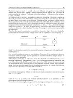
The constitutive equation relating stresses, σ, and strains, , in the k
th
lamina is (using standard notation for
composites):
where the values are the stiffness matrix components in the specimen system of axes 1, 2, 3 of the k
th
lamina, and are obtained from the values in the axes related to the fiber direction x, y, z by using the appropriate
geometric transformation. For a beam specimen, the stresses σ
2
and σ
6
(transverse and interlaminar shear) can
generally be neglected in comparison with σ
1
although M.M. Wallace and C.W. Bert cite cases where this may
not always be so (Ref 12).
With the appropriate geometric transformation, these stresses can be converted from the specimen axes to the
fiber directions. It is then possible to calculate the stresses in the fiber direction σ
x
(that is, σ
L
), normal to it σ
v
(that is, σ
T
), and the shear components σ
xy
(that is, σ
LT
). The total energy stored in the x (or L) direction, Z
L
, for
example, can then be calculated, and the energy dissipation in this layer and in this direction can then be given
by:
ΔZ
L
=Ψ
L
·Z
L
For the beam, the overall specific damping capacity, Ψ
ov
, is then given by the total energy dissipated divided by
the total energy stored:
(Eq 3)
If the elastic moduli and damping coefficients are known for the unidirectional material, it is possible to
calculate the overall damping of a beam. R.G. Ni and R.D. Adams (Ref 11) gave the theory for generally
laminated beams and obtained excellent agreement with the measured results.
Whereas specimens with all the layers at θ will twist as they are bent, the twisting can be restrained internally
by using several layers at ±θ. The damping contributions can again be assessed, and the measured values
accounted for (Ref 10, 11). Figure 11 shows theoretical predictions and experimental measurements for the
modulus and damping of a series of CFRP beams made with ten layers of high-modulus carbon fibers in epoxy
resin, alternately at ±θ. Note that the modulus is higher than that of the off-axis specimens because of the
internal restraint, while the damping is generally lower.
Fig. 11 Variation of flexural Young's modulus (E
f
) and damping (Ψ) with ply angle ±θ for high-modulus
carbon fiber in DX209 epoxy resin. V
f
= 0.5
More generally, laminated composites, as shown in Fig. 10, are commonly used in practice. Fortunately, the
same method as that just described can be used to predict damping. Figure 12 shows the excellent agreement
between theory and experiment for the variation of damping (and stiffness) with θ of a symmetrical, high-
modulus, graphite-fiber-reinforced epoxy plate. Beam specimens were cut at angles from–90° to +90° relative
to the fiber direction in the outer layer of this (0°,–60°, +60°)
s
plate.
Fig. 12 Variation of flexural modulus (E) and damping (Ψ) with outer layer fiber orientation angle (θ)
for 0°,–60°, 60°)
s
made from high-modulus carbon fibers in DX210 epoxy resin
References cited in this section
10. R.D. Adams and D.G.C. Bacon, Effect of Fibre Orientation and Laminate Geometry on the Dynamic
Properties of CFRP, J. Compos. Mater., Vol 7, 1973, p 402–428
11. R.G. Ni and R.D. Adams, The Damping and Dynamic Moduli of Symmetric Laminated Composite
Beams—Theoretical and Experimental Results, J. Compos. Mater., Vol 18, 1984, p 104–121
12. M.M. Wallace and C.W. Bert, Transfer-Matrix Analysis of Dynamic Response of Composite-Material
Structural Elements With Material Damping, Shock & Vib. Bull. 50, Part 3, Sept 1980, p 27–38
Damping Properties
Laminated Plates
Fiber-reinforced plates of various shapes and different boundary conditions (free, clamped, and hinged)
commonly occur in practice. Designers need to be able to predict the stiffness parameters and damping values
of such plates for conditions such as aeroelasticity, acoustic fatigue, and so on. Much attention has been
devoted to stiffness predictions, but very little to damping. The objective here is to develop a suitable
mathematical model that can be used to predict the damping values of plates laminated from fibers of various
types at various orientations. Such is the mathematical complexity of the equation of motion of plates (even
those made from isotropic materials) that closed-form solutions exist only for special cases, such as hinged
(simply supported) rectangular plates and circular plates (involving Bessel functions). The solution is therefore
best obtained using finite- element techniques, which can readily accommodate different shapes, thicknesses,
and boundary conditions. Some examples are given by P. Cawley and R.D. Adams (Ref 13).
All the plates discussed here are midplane symmetric, which eliminates bending-stretching coupling. It is,
however, possible to include this effect in the analysis if asymmetrical laminates are used.
The first ten modes of vibration of a typical plate can be adequately described by using a coarse finite-element
mesh with six elements per side (6 × 6 = 36 elements for a rectangular plate). The essence of the technique is
first to determine the values of strain energy stored because of the stresses relative to the fiber axes of each
layer of each element. Use of modulus parameters determined from unidirectional bars makes it possible to
determine the total energy stored in each layer of each element. These are then summed through the thickness
to give the energy stored in each element (related to the strains and the mean elasticity matrix for the element).
It is then possible to use standard finite- element programs and avoid the mathematical complication of working
in terms of the standard plate equations. This approach provides the stiffness of the plate, the maximum strain
energy, U, stored in any given mode of vibration, the natural frequencies, and the mode shape. The energy
dissipated in an element of unit width and length situated in the k
th
layer can also now be determined. This is
done by transforming the stresses and strains to the fiber directions and using the damping properties of 0° bars.
The energy dissipated in the element in the k
th
layer is integrated over the whole area of the plate, and
contributions of each layer are summed to give ΔU, the total energy dissipated in the plate. The overall specific
damping capacity, Ψ
ov
, is then given by Ψ
ov
=ΔU/U. Alternatively, the damping can first be summed through the
thickness of the damped element to give a damped element stiffness matrix. This can then be treated by
standard finite element techniques (Ref 14).
It is useful to express in the mathematical terms the technique described previously. The maximum strain
energy, U, is obtained as for an undamped system as follows:
(Eq 4)
where
ij
and σ
ij
are the strains and stresses related to the fiber direction, and V refers to the volume.
This equation may be reduced to a standard form as:
(Eq 5)
where {δ} is the nodal point displacement matrix. Here, five degrees of freedom for each nodal point and eight
nodal points for each element are used, and [K] is the stiffness matrix. In the evaluation of the maximum strain
energy, U, the Young's modulus of 0° and 90° unidirectional fiber-reinforced beams, E
L
, E
T
, and the shear
modulus of a 0° unidirectional rod, G
LT
, are used, Now:
(Eq 6)
where δ(ΔU) is the energy dissipated in each element, and is defined as:
δ(ΔU) =δ(ΔU
1
) +δ(ΔU
2
) +δ(ΔU
23
) +δ(ΔU
13
)+δ(ΔU
12
)
and
Ψ
LT 13
σ
13
Ψ
LT 12
σ
12
where subscript 1 denotes the fiber direction, while 2 and 3 denote the two directions transverse to the direction
of the fibers, and Ψ
L
, Ψ
T
, and Ψ
LT
are the associated damping capacities that are also obtained from tests on
unidirectional beams.
We may now reduce Eq 7 to matrix form as:
(Eq 7)
where:
Using the same method as with Eq 4, Eq 7 may be reduced to:
(Eq 8)
where {δ} is the same matrix as in Eq 4 and was obtained from the finite-element results. The stiffness matrix
of the damped system is [K
d
], and it may be evaluated separately. D.X. Lin, R.G. Ni, and R.D. Adams described
this method in much more detail (Ref 14).
Some results are given for theoretical predictions and experimental measurements on several plates made from
glass or high-modulus carbon fibers in DX210 epoxy resin. The plates were made of 8 or 12 layers of
preimpregnated fiber to give different laminate orientations; details of the plates used are given in Table 1. The
material properties used in the theoretical prediction are given in Table 2. All the values in this table were
established either by using beam specimens cut from a unidirectional plate (longitudinal and transverse
damping and Young's moduli) or cylindrical specimens (for measuring the shear modulus and damping in
torsion). It should be noted that the value of the torsional damping of a bar with fibers at 90° to the axis, Ψ
23
, is
not important in the prediction, because changing it from 6% to 15% gave no significant difference to the
overall theoretical results. In the prediction, Ψ
23
is taken as the same value as Ψ
12
, which is the value of
torsional damping of a unidirectional rod in longitudinal shear. Because of variations in the fiber volume
fraction of the plates, the material properties used in the theoretical prediction were each corrected from a
standard set given for 50 vol%, using the method of R.G. Ni and R.D. Adams (Ref 11). The plates were
vibrated in the free-free condition (with all the edges freely supported). Although hinged or clamped edges can
be readily incorporated into the finite element model, they are not easy to reproduce in an experiment. Figures
13 and 14 show, for the first six free-free modes, the theoretical prediction and experimental results of CFRP
plates for various fiber orientations. On the whole, there is good agreement between the predicted and measured
values. Mode 6 in plate 3 could not be obtained experimentally because the input energy from the transient
technique used for measuring the frequency and damping (Ref 15) was insufficient. Figures 15 and 16 give the
results for GFRP plates in free-free vibration. All show good agreement between prediction and measurement.
Table 1 Plate data
Plate number
Material
No. of layers
Density, g/cm
3
V
f
Ply orientation
1
CFRP
(a)
8 1.446 0.342
(0°, 90°, 0°, 90°)
s
(b)
2
CFRP 12 1.636 0.618
(0°,–60°, 60°, 0°,–60°, 60°)
s
3
GFRP 8 1.813 0.451
(0°, 90°, 0°, 90°)
s
4
GFRP 12 2.003 0.592
(0°,–60°, 60°, 0°,–60°, 60°)
s
(a) (a) Using high-modulus carbon fiber. (b) s represents midplane symmetric.
Table 2 Moduli and damping values for materials used in the plates
E
L
E
T
G
LT
Material
GPa 10
6
psi
GPa 10
6
psi
GPa
10
6
psi
ψ
L
, %
ψ
T
, %
ψ
LT
, %
v
1
,v
2
V
f
HMS-DX210
(a)
172.1
30.0 7.20 1.04 3.76 0.55 0.45 4.22 7.05 0.3 0.50
Glass-DX210
37.87
5.49 10.90
1.58 4.91 0.71 0.87 5.05 6.91 0.3 0.50
DX210-BF
3
400
3.21 0.47 3.21 0.47 1.20 0.17 6.54 6.54 6.68 0.34 0
(a) (a) HMS, high-modulus carbon fiber
Fig. 13 Natural frequency and damping of various modes of an eight-layer (0°, 90°, 0°, 90°)
s
CFRP plate
(plate 1). Experimental values in parentheses
Fig. 14 Natural frequency and damping of various modes of a 12-layer (0°,–60°, 60°, 0°,–60°, 60°)
s
CFRP
plate (plate 2). Experimental values in parentheses
Fig. 15 Natural frequency and damping of various modes of an eight-layer (0°, 90°, 0°, 90°)
s
GFRP plate
(plate 3). Experimental values in parentheses
Fig. 16 Natural frequency and damping of various modes of a 12-layer (0°,–60°, +60°, 0°,–60°, +60°)
s
GFRP plate (plate 4). Experimental values in parentheses
The effect of air damping and the additional energy dissipation associated with the supports affect the results of
the very low damping modes, such as mode 4 of plate 1, mode 4 of plate 3, and so on. These are essentially
beam modes in which the large majority of the strain energy is stored in tension/compression in the fibers and
not in matrix tension or shear. However, the results for all the plates used are satisfactory, even when the
specimens have imperfections, such as slight variations in thickness and the nominal angle of the fibers (±2° to
(±3° error). It can be said that the more twisting there is, the higher the damping. For instance, for an eight-layer
cross-ply (0°/90°) GFRP plate (Fig. 15), the two beam-type modes, that is, modes 2 and 3, appear to be similar,
but the relationship of the nodal lines to the outer fiber direction means that the higher mode has much less
damping than the lower one. The other modes of vibration of this plate all involve much more plate twisting,
and hence matrix shear, than do modes 2 and 3, and so the damping is higher.
Design Considerations for Plates. It is important for designers to realize the significance of these results, which
show that for all the plates, the damping values are different for each mode. For instance, for the all-0° square
GFRP plate in Fig. 17, the damping of the first mode was over 14 times that of the sixth mode. Also, it should
be noted that some modes may have much less damping than others, especially when most of the fibers are in
one direction. If such a low-damping mode has its natural frequency close to or in the frequency range of any
excitation, it may well lead to excessive motion and cause fatigue, noise radiation, component malfunction, and
so on.
Fig. 17 Variation of natural frequencies and damping with the ratio of thickness to the area of a square
plate (all 0°) GFRP. V
f
= 0.50
D.X. Lin, R.G. Ni, and R.D. Adams (Ref 14) showed how the prediction of natural frequencies and damping
values could be simplified for geometrically similar structures by using a series of design charts. First, the
damping is a function only of the mode shape. Thus, for a series of square plates with a given fiber orientation,
the damping value of each mode is constant, irrespective of the dimensions of the plate. It should be noted that
the damping of epoxy and similar high-performance resins is not frequency-dependent in the way that is
normally associated with thermoplastics, except near the glass transition temperature, which would normally be
outside the design range, even though aerospace structures have wide temperature range of operation.
Furthermore the natural frequencies can all be scaled from a series of simple numbers, or read off a design
chart. Figure 17 shows such a chart for an all-0° GFRP plate that has a volume fraction of 0.50. For a given
mode, the natural frequency of the tth mode, f
i
, is given by f
i
=k
i
h/ a
2
, where h is the plate thickness and a is its
side length. Thus, it is possible, by using charts such as those in Fig. 17, to determine quickly and accurately the
natural frequency and damping of any of the first six modes of a square plate with that particular fiber
arrangement.
Because the volume fraction can also change, it is necessary to construct a further series of graphs to allow for
this. Figure 18 shows the variation of natural frequency and damping of an all-0° GFRP plate with volume
fraction. Again, the damping will not change with plate dimensions (h and a), although it does decrease as the
volume fraction increases. Figure 18 is based on a plate for which h/a
2
= 0.032 m
–1
. Now, because:
f
i
=k
i
h/a
2
k
i
must be some function of inter alia, the volume fraction. Thus:
and by cross-correlating from charts such as those given in Fig. 17 and 18, it is possible to predict the damping
and frequency of a given mode as h, a, and V
f
vary (Ref 14).
Fig. 18 Variation of natural frequencies (f
n
) and damping (Ψ) of a GFRP (all 0°) plate with fiber volume
fraction (V
f
). α=h/a
2
= 0.32 m
–1
References cited in this section
11. R.G. Ni and R.D. Adams, The Damping and Dynamic Moduli of Symmetric Laminated Composite
Beams—Theoretical and Experimental Results, J. Compos. Mater., Vol 18, 1984, p 104–121
13. P. Cawley and R.D. Adams, The Predicted and Experimental Natural Modes of Free- Free CFRP Plates,
J. Compos. Mater., Vol 13, 1978, p 336–347
14. D.X. Lin, R.G. Ni, and R.D. Adams, Prediction and Measurement of the Vibrational Damping
Parameters of Carbon and Glass Fibre-Reinforced Plastics Plates, J. Compos. Mater., Vol 18, 1984, p
132–152
15. D.X. Lin and R.D. Adams, Determination of the Damping Properties of Structures by Transient Testing
Using Zoom-FFT., J. Phys. E., Sci. Instrum., Vol 18, 1985, p 161–165
Damping Properties
Woven Fibrous Composites
Woven fiber-reinforce plastics are becoming increasingly important because they have the following
advantages over laminates made from individual layers of unidirectional material:
• Improved formability and drape
• Bidirectional reinforcement in a single layer
• Improved impact resistance
• Balanced properties in the fabric plane
The woven composite is formed by interlacing two sets of threads, the warp and the weft, in a wide variety of
weaves and balances.
Figure 19 shows the damping results obtained by cutting a series of beans at various angles, θ, from a 16-ply
plate of CFRP. The fibers were woven to a balanced five-harness satin weave pattern in which one weft thread
was interwoven with every fifth warp thread. This weave is the most widely used in laminates, because it gives
higher mechanical properties than do plain and twill weaves, due to reduced crimping. The damping increases
from about 1% at θ= 0° and 90° to a maximum of about 6% at θ= 45°. R.G. Ni and R.D. Adams' prediction
(Ref 11) for a 0°/90° cross-ply made from unidirectional laminae is also shown on Fig. 19, and is in reasonable
agreement with the experimental data for the woven material. The damping of the woven material is modified
because the twisting of the specimens is restrained internally by the perpendicular arrangement of the warp and
weft threads.
Fig. 19 Variation of specific damping capacity(Ψ) for a series of beams cut at various angles (θ) from a
woven 16-ply CFRP plate
While further work is necessary to characterize the various weaves, it appears that the results will, at first
approximation, be similar to those for laminates made from unidirectional laminae with the same in-lane fiber
orientations.
Reference cited in this section
11. R.G. Ni and R.D. Adams, The Damping and Dynamic Moduli of Symmetric Laminated Composite
Beams—Theoretical and Experimental Results, J. Compos. Mater., Vol 18, 1984, p 104–121
Damping Properties
Sandwich Laminates
To maximize the stiffness of GFRP laminates, it is common to add thin skins of CFRP. R.G. Ni, D.X. Lin, and
R.D. Adams (Ref 16) made mathematical predictions of the dynamic properties of such hybrid laminates. They
obtained excellent agreement between their experimental results and their theoretical predictions for the
damping and moduli of plates, and of beams cut from these plates. These authors also showed how to maximize
both the stiffness of a laminate from the ratio of the amounts of glass and carbon, and their relative costs.
The theoretical analysis showed that the effect of the core material on the flexural modulus and damping of this
type of hybrid is generally not great. This allows some freedom in choosing the orientation of the GFRP core,
and even in the selection of core materials.
Reference cited in this section
16. R.G. Ni, D.X. Lin, and R.D. Adams, The Dynamic Properties of Carbon-Glass Fibre Sandwich-
Laminated Composites: Theoretical, Experimental and Economic Considerations, Composites, Vol 15,
1984, p 297–304
Damping Properties
Effect of Temperature
Many composites are based on polymeric matrices, usually epoxy resins, for which there are temperature-
dependent damping capacities and moduli. While the influence of frequency on damping and modulus is not as
strong for epoxies as it is for the high-damping polymers, as used in constrained-layer and similar damping
treatments, it is not negligible. Figure 20 shows the change of E
L
, E
T
, and G
LT
of a unidirectional CFRP
composite over the range of–50 to +200 °C (–60 to +390 °F). (The matrix material was DX209 epoxy resin
cured for 2 h at 180 °C (355 °F) and postcured for 6 h at 150 °C (300 °F).) A logarithmic scale was used, and it
can be seen that the 2 matrix-dependent moduli, E
t
and G
LT
, were significantly reduced at temperatures above
150 °C (300 °F). Indeed, the transverse specimen (90° orientation) could not be tested at temperatures above
150 °C (300 °F), as it sagged under its own weight. In contrast, the 0° modulus was essentially unaffected until
the matrix became shear soft, at which point the deformation became more by shear than by bending and fiber
deformation. Figure 21 shows damping on a logarithmic scale and the much higher damping levels that are
available in shear and transverse loading than in longitudinal tension/compression. The Ψ
L
damping is due not
only to increased matrix damping, according to the rule of mixtures, but also to the enhanced shear deformation
referred to previously. The damping peak, at about 180 °C (360 °F), represents classical viscoelastic behavior.
Testing beyond 200 °C (390 °F) was impossible because of charring.
Fig. 20 Variation of longitudinal modulus (E
L
), transverse modulus (E
T
), and longitudinal shear modulus
(G
LT
) with temperature for high-modulus carbon fibers in DX209 epoxy resin. V
f
= 0.5
Fig. 21 Variation of longitudinal damping (Ψ
L
), transverse damping (Ψ
LT
) with temperature for high-
modulus carbon fibers in DX209 epoxy resin. V
f
= 0.5
At lower temperatures, the β relaxation phenomenon comes into effect. This is illustrated in Fig. 22 for a
cryogenic grade, woven glass-fiber- reinforced epoxy material.
Fig. 22 Variation of specific damping capacity (Ψ) with temperature for a glass cloth-epoxy specimen
To achieve a wide range of resin properties, a standard resin was modified by the addition of a flexibilizer. By
varying the proportions of resin to flexibilizer, precondensates with different glass transition temperatures were
formed. Shell Epikote 828 (Shell Oil Co.) was used as the standard resin and flexibilized by the addition of
Epikote 871 in the proportions 1:1 and 2:1 (828/ 871) by weight to give FO (pure 828), F50 (50% flexibilizer),
and F33 (33% flexibilizer). The resin was made into prepreg with type II (high- tensile strength) carbon fiber
and laminates prepared from it. Figure 23 shows that increasing the flexibilizer content increases the damping
and decreases the glass transition temperature.
Fig. 23 Variation of specific damping capacity (Ψ) with temperature for 0° unidirectional composite
made from Epikote flexibilized resin. V
f
= 0.5
Figure 24 shows the combined effect of fiber orientation and temperature on the flexural damping of a series of
beams cut at various angles from a unidirectional plate (type II carbon fibers in DX209 epoxy resin). The
damping results of specimens with angles of 0° to 40° are presented in Fig. 24; specimens from 50° to 70° (not
shown) showed very little difference in behavior. The frequency of vibration used in measuring the glass
transition temperature varied from 324 Hz for the 0° specimen to 120 Hz for the 40° specimen. There was a
reduction of the peak temperature of about 10 °C over the range of fiber angles of 0° to 20°.
Fig. 24 The effect of fiber orientation on the variation of specific damping capacity (Ψ) with temperature
for high- modulus carbon fibers in DX209 epoxy resin. V
f
= 0.5
The damping properties near the relaxation peaks for a range of frequencies are given for ±10° and ±20°
specimens (Fig. 25). In both cases, there is a reduction of the damping peak with increase of frequency. A
comparison of traces with approximately the same frequency at the peak (that is, 249 Hz, ±10° and 235 Hz,
±20°), showed that the damping was almost identical, at about 53% SDC, but that the peak temperature for the
±20° specimen was nearly 20 °C (36 °F) below that of the ±10° specimen. The contribution of shear damping
for the ±20° specimen is much larger than is that for the ±10° specimen (Fig. 11), and the longitudinal tensile
component is almost negligible. However, due to the fairly high flexural modulus of the ±10° specimen, E±10,
and its relatively low torsion modulus, G±10, there will be shear deformation in flexure. The difference
between the two types of shears is one of direction; the flexural shear is denoted by σ
zx
where z is perpendicular
to the plane of the laminate, and the shear that is due to the fiber angle is denoted by σ
xy
. For 0° specimens, σ
zx
and σ
xy
lie in the plane of symmetry, and the effect will be identical, but for more complex laminates involving
adjacent laminae at different angles, the result is not as obvious.
Fig. 25 Variation of specific damping capacity (Ψ) with temperature for ±10° and ±20° angle-plies made
from high-modulus carbon fibers in DX209 epoxy resin. V
f
= 0.5
The effect of temperature on flexural modulus depends to a large extent on the lay-up; where the fiber angle is
near 0°, there is only a small reduction at high temperatures, but at larger fiber angles (20 to 90°), the modulus
can decrease by more than an order of magnitude.
Damping Properties
Relationship Between Damping and Strength
If improving damping properties of a laminate at no detriment to its mechanical properties is an objective, it is
interesting to examine the differences between ±15° angle plies and 0°/90° cross plies. In flexure, the strengths
and moduli are almost identical for the range of fibers, whereas the damping of the angle plies is double that of
the cross plies. In torsion, the shear moduli of angle plies are largely dependent on the fiber modulus and are
much larger than the cross-ply shear moduli, the values of which are nominally independent of fiber modulus.
The damping of angle plies is, in this latter case, less than half that of the cross plies.
Thus, different lamination geometries and fiber moduli can be arranged to give some common properties
between laminates while having very different properties in other modes. In design, this gives greater flexibility
to cater for strength and stiffness in one direction, with optional properties in others, according to requirements,
than can possibly be achieved with isotropic materials. The damping properties of laminates can now be added
to these design parameters (Ref 17).
Reference cited in this section
17. R.D. Adams and D.G.C. Bacon, The Effect of Fibre Modulus and Surface Treatment on the Modulus,
Damping, and Strength of Carbon-Fibre-Reinforced Plastics, J. Phys. D., Appl. Phys., Vol 7, 1974, p 7–
23
Damping Properties
Composites Versus Metals
To put the damping of composites in context, a comparison should be made with the damping of metals. Figure
26 shows the variation of damping with cyclic stress amplitude for a range of common structural metals. The
metallic specimens were tested in axial vibration (tension/ compression) using the apparatus described by R.D.
Adams and A.L Percival (Ref 18); more details of the results are given in Ref 19 and 20. Composites provide
slightly higher damping than steels, but significantly less than conventional high-damping alloys. On the other
hand, low-weight high-strength alloys such as aluminum and titanium give extremely low damping; values of
less than 0.01% SDC have been reported (Ref 21).
Fig. 26 Specific damping capacity (Ψ) versus stress for a range of ferrous and nonferrous metals. Nickel
(AV), annealed in vacuum. K-123, K-148, K-N, grades of cast iron. 18/8, stainless steel. Armco (AV), low-
carbon, iron, annealed in vacuum, BB(SR), 0.12% carbon steel, stress relieved. BSS 250, Naval brass,
and phosphor bronze are copper- based alloys. CA, DA, high-carbon steels. HE 15-W, Duralumin
aluminum alloy. Ti 715, titanium alloy
References cited in this section
18. R.D. Adams and A.L Percival, Measurement of the Strain-Dependent Damping of Metals in Axial
Vibration, J. Phys. D., Appl. Phys., Vol 2, 1969, p 1693–1704
19. R.D. Adams, The Damping Characteristics of Certain Steels, Cast Irons, and Other Metals, J. Sound and
Vibr., Vol 23, 1972, p 199–216
20. R.D. Adams, Damping of Ferromagnetic Materials at Direct Stress Levels Below the Fatigue Limit, J.
Phys. D., Appl. Phys., Vol 5, 1972, p 1877–1889
21. G.A. Cottell, K.M. Entwistle, and F.C. Thompson, The Measurement of the Damping Capacity of
Metals in Torsional Vibration, J. Inst. Metals, Vol 74, 1948, p 373–424
Damping Properties
Acknowledgments
This article is adapted from R.D. Adams, Damping Properties Analysis of Composites, Composites, Vol 1,
Engineered Materials Handbook, ASM International, 1987, p 206–217.
Damping Properties
References
1. S.A. Suarez, R.F. Gibson, C.T. Sun, and S.K. Chaturvedi, The Influence of Fiber Length and Fiber
Orientation on Damping and Stiffness of Polymer Composite Materials, Exp. Mech., Vol 26, 1986, p
175–184
2. R.D. Adams and D.G.C. Bacon, The Dynamic Properties of Unidirectional Fibre Reinforced
Composites in Flexure and Torsion, J. Compos. Mater., Vol 7, 1973, p 53–67
3. D.F. Adams and D.R. Doner, Longitudinal Shear Loading of a Unidirectional Composite, J. Compos.
Mater., Vol 1, 1967, p 4–17
4. Z. Hashin, Complex Moduli of Viscoelastic Composites, II, Fibre Reinforce Materials, Int. J. Solids
Struct., Vol 6, 1970, p 797–804
5. R.G. Ni and R.D. Adams, A Rational Method for Obtaining the Dynamic Mechanical Properties of
Laminae for Predicting the Stiffness and Damping of Laminated Plates and Beams, Composites, Vol 15,
1984, p 193–199
6. R.D. Adams and D.F Short, The Effect of Fibre Diameter on the Dynamic Properties of Glass-Fibre-
Reinforced Polyester Resin, J. Phys. D. Appl. Phys., Vol 6, 1973, p 1032–1039
7. R.D. Adams, The Dynamic Longitudinal Shear Modulus and Damping of Carbon Fibres, J. Phys. D.,
Appl. Phys., Vol 8, 1975, p 738–748
8. S.W. Tsai and H.T. Halpin, Introduction to Composite Materials, Technomic Publishing Co., Westport,
CT, 1980
9. S. Chang and C.W. Bert, Analysis of Damping for Filamentary Composite Materials, Composite
Materials in Engineering Design, B.R. Noton, Ed., American Society for Metals, 1973, p 51–62
10. R.D. Adams and D.G.C. Bacon, Effect of Fibre Orientation and Laminate Geometry on the Dynamic
Properties of CFRP, J. Compos. Mater., Vol 7, 1973, p 402–428
11. R.G. Ni and R.D. Adams, The Damping and Dynamic Moduli of Symmetric Laminated Composite
Beams—Theoretical and Experimental Results, J. Compos. Mater., Vol 18, 1984, p 104–121
12. M.M. Wallace and C.W. Bert, Transfer-Matrix Analysis of Dynamic Response of Composite-Material
Structural Elements With Material Damping, Shock & Vib. Bull. 50, Part 3, Sept 1980, p 27–38
13. P. Cawley and R.D. Adams, The Predicted and Experimental Natural Modes of Free- Free CFRP Plates,
J. Compos. Mater., Vol 13, 1978, p 336–347
14. D.X. Lin, R.G. Ni, and R.D. Adams, Prediction and Measurement of the Vibrational Damping
Parameters of Carbon and Glass Fibre-Reinforced Plastics Plates, J. Compos. Mater., Vol 18, 1984, p
132–152
15. D.X. Lin and R.D. Adams, Determination of the Damping Properties of Structures by Transient Testing
Using Zoom-FFT., J. Phys. E., Sci. Instrum., Vol 18, 1985, p 161–165
16. R.G. Ni, D.X. Lin, and R.D. Adams, The Dynamic Properties of Carbon-Glass Fibre Sandwich-
Laminated Composites: Theoretical, Experimental and Economic Considerations, Composites, Vol 15,
1984, p 297–304
17. R.D. Adams and D.G.C. Bacon, The Effect of Fibre Modulus and Surface Treatment on the Modulus,
Damping, and Strength of Carbon-Fibre-Reinforced Plastics, J. Phys. D., Appl. Phys., Vol 7, 1974, p 7–
23
18. R.D. Adams and A.L Percival, Measurement of the Strain-Dependent Damping of Metals in Axial
Vibration, J. Phys. D., Appl. Phys., Vol 2, 1969, p 1693–1704
19. R.D. Adams, The Damping Characteristics of Certain Steels, Cast Irons, and Other Metals, J. Sound and
Vibr., Vol 23, 1972, p 199–216
20. R.D. Adams, Damping of Ferromagnetic Materials at Direct Stress Levels Below the Fatigue Limit, J.
Phys. D., Appl. Phys., Vol 5, 1972, p 1877–1889
21. G.A. Cottell, K.M. Entwistle, and F.C. Thompson, The Measurement of the Damping Capacity of
Metals in Torsional Vibration, J. Inst. Metals, Vol 74, 1948, p 373–424
Bolted and Bonded Joints
L.J. Hart-Smith, The Boeing Company
Introduction
THE STRUCTURAL EFFICIENCY of a composite structure is established, with very few exceptions, by its
joints, not by its basic structure. Joints can be manufacturing splices planned at predetermined locations in the
structure or unplanned repairs that could be needed anywhere in the structure. Consequently, unless a specific
application needs no provision for repairs or uses throw-away unrepairable components, the correct sequence
for design is to first locate and size the joints, in fiber patterns optimized for that task, and then fill in the gaps
(the basic structure) in between.
This sequence is a marked departure from normal practice for conventional ductile metal alloys and is
necessitated by the relative brittleness of fiber-reinforced composites. Yielding of ductile metals usually
reduces the stress concentrations around bolt holes so that there is only a loss of area, with no stress
concentration at ultimate load on the remaining (net) section at the joints. With composites, however, there is
no relief at all from the elastic stress concentration if the holes or cutouts are large enough. Even for small holes
in composite structures, the stress- concentration relief is far from complete, although the local disbonding
(between the fibers and resin matrix and local intraply and interply splitting close to the hole edge) does locally
alleviate the most severe stress concentrations.
The reason for emphasizing the importance of joints in the design of composite structures is that the availability
of large computer optimization programs and the highly deficient treatment of residual thermal stresses within
the resin in most of the composite laminate theories have combined to create the illusion that optimized
composite structures will necessarily be highly orthotropic and tailored precisely to match the load conditions
and stiffness requirements. (There are no terms in most theories to allow for separate residual thermal stresses
in the fibers or matrix of the monolayer, which serves as the building block for cross-plied laminate theories.
The omission is due to the artificial homogenization of distinctly two-phase composite materials into
mathematically simpler one-phase models. Fortunately, there is finally one mechanistic theory—see the article
“Characterizing Strength From a Structural Design Perspective” in this Volume and Ref 1 and 2—in which
there is a proper distinction between the fiber and resin constituents in fiber-polymer composites. Separate
characterization of each failure mechanism in each constituent has shown that only a few true materials
properties are needed to explain what appear to be many different loading conditions at the laminate and lamina
level. The progressively more widespread use of this approach will lead to far less reliance on empiricism and
costly testing than has been necessary in the past.)
If composite structures were highly orthotropic and precisely tailored, the task of designing joints in composites
would be much more difficult than it is now. The capability of bolted joints in such highly orthotropic materials
is often unacceptably low. Hence, the laminate can never be loaded to the levels suggested by lamination theory
for unnotched laminates.
Fortunately, or unfortunately, depending on one’s point of view, the strength of composite structures with both
loaded and unloaded holes depends only slightly on the fiber pattern (for nearly quasi-isotropic laminates); the
stress-concentration factor increases almost as rapidly as the unnotched strength for slightly orthotropic
patterns. Indeed, throughout the range of fiber patterns surrounding the quasi-isotropic lay-up, the bearing
strengths and gross-section strengths are almost constant, which simplifies the design process considerably. A
valid case can often be made for a small amount of orthotropy, within the shaded area in Fig. 1, particularly
when there is a preferred load direction or stiffness requirement that must be met. The farther a laminate pattern
is outside the shaded area, the more likely it is to fail prematurely by through-the-thickness cracks parallel to
the maximum concentration of fibers.
Fig. 1 Selection of lay-up pattern for fiber-reinforced composite laminates. All fibers in 0°, +45°, 90°, or–
45° direction. Note: lightly loaded minimum gage structures tend to encompass a greater range of fiber
patterns than indicated, because of the unavailability of thinner plies.
Even for those few truly non-strength-critical uses of highly orthotropic fiber patterns, such as space structures
with zero coefficient of thermal expansion and one-shot missiles, there must be a transition to nearly quasi-
isotropic patterns around any bolt holes; the structural efficiency of bolted joints in highly orthotropic laminates
is known to be inadequate. Therefore, the material presented here is applicable to all sensible composite
structures, although it deliberately excludes mechanical joints in highly orthotropic materials. If joints were
assessed in terms of an efficiency comparing the strength of the joint with the strength of the same unnotched
laminate, far stronger composite structures would be designed than have been when this consideration has been
overlooked. As is explained later, it is extremely difficult to attain a 50% joint efficiency (even with multirow
bolted joints); even an efficiency of 40% in a single-row joint requires the use of the most appropriate pitch-to-
diameter (w/d) ratio. Attention is confined to uniaxial membrane loading, because most of the relevant test data
on bolted joints are similarly restricted, and because the analysis methods for off-axis loading and applied
bending moments are still being developed.
The design of joints in nearly quasi-isotropic composites is straightforward, once the notion of joint efficiency
as a function of geometry is accepted, although it is also necessary to allow for nonlinearities in the material
behavior; linearly elastic analyses are far too conservative. The analysis of adhesively bonded joints using
elastic-plastic adhesive models has advanced to the stage at which it can legitimately be called a science. The
design of straightforward bonded joints has been reduced to following a few procedures and obeying a few
simple design refinements to prevent premature failures due to induced peel loads. The design and analysis of
the more complex stepped-lap bonded joints needed for much thicker and more highly loaded bonded structures