Image Formation & Display
Bạn đang xem bản rút gọn của tài liệu. Xem và tải ngay bản đầy đủ của tài liệu tại đây (678.16 KB, 24 trang )
373
CHAPTER
23
Image Formation & Display
Images are a description of how a parameter varies over a surface. For example, standard visual
images result from light intensity variations across a two-dimensional plane. However, light is
not the only parameter used in scientific imaging. For example, an image can be formed of the
temperature of an integrated circuit, blood velocity in a patient's artery, x-ray emission from a
distant galaxy, ground motion during an earthquake, etc. These exotic images are usually
converted into conventional pictures (i.e., light images), so that they can be evaluated by the
human eye. This first chapter on image processing describes how digital images are formed and
presented to human observers.
Digital Image Structure
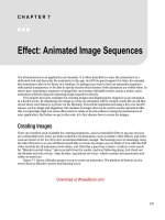
Figure 23-1 illustrates the structure of a digital image. This example image is
of the planet Venus, acquired by microwave radar from an orbiting space
probe. Microwave imaging is necessary because the dense atmosphere blocks
visible light, making standard photography impossible. The image shown is
represented by 40,000 samples arranged in a two-dimensional array of 200
columns by 200 rows. Just as with one-dimensional signals, these rows and
columns can be numbered 0 through 199, or 1 through 200. In imaging jargon,
each sample is called a pixel, a contraction of the phrase: picture element.
Each pixel in this example is a single number between 0 and 255. When the
image was acquired, this number related to the amount of microwave energy
being reflected from the corresponding location on the planet's surface. To
display this as a visual image, the value of each pixel is converted into a
grayscale, where 0 is black, 255 is white, and the intermediate values are
shades of gray.
Images have their information encoded in the spatial domain, the image
equivalent of the time domain. In other words, features in images are
represented by edges, not sinusoids. This means that the spacing and
number of pixels are determined by how small of features need to be seen,
The Scientist and Engineer's Guide to Digital Signal Processing374
rather than by the formal constraints of the sampling theorem. Aliasing can
occur in images, but it is generally thought of as a nuisance rather than a major
problem. For instance, pinstriped suits look terrible on television because the
repetitive pattern is greater than the Nyquist frequency. The aliased
frequencies appear as light and dark bands that move across the clothing as the
person changes position.
A "typical" digital image is composed of about 500 rows by 500 columns. This
is the image quality encountered in television, personal computer applications,
and general scientific research. Images with fewer pixels, say 250 by 250, are
regarded as having unusually poor resolution. This is frequently the case with
new imaging modalities; as the technology matures, more pixels are added.
These low resolution images look noticeably unnatural, and the individual
pixels can often be seen. On the other end, images with more than 1000 by
1000 pixels are considered exceptionally good. This is the quality of the best
computer graphics, high-definition television, and 35 mm motion pictures.
There are also applications needing even higher resolution, requiring several
thousand pixels per side: digitized x-ray images, space photographs, and glossy
advertisements in magazines.
The strongest motivation for using lower resolution images is that there are
fewer pixels to handle. This is not trivial; one of the most difficult problems
in image processing is managing massive amounts of data. For example, one
second of digital audio requires about eight kilobytes. In comparison, one
second of television requires about eight Megabytes. Transmitting a 500 by
500 pixel image over a 33.6 kbps modem requires nearly a minute! Jumping
to an image size of 1000 by 1000 quadruples these problems.
It is common for 256 gray levels (quantization levels) to be used in image
processing, corresponding to a single byte per pixel. There are several reasons
for this. First, a single byte is convenient for data management, since this is
how computers usually store data. Second, the large number of pixels in an
image compensate to a certain degree for a limited number of quantization
steps. For example, imagine a group of adjacent pixels alternating in value
between digital numbers (DN) 145 and 146. The human eye perceives the
region as a brightness of 145.5. In other words, images are very dithered.
Third, and most important, a brightness step size of 1/256 (0.39%) is smaller
than the eye can perceive. An image presented to a human observer will not
be improved by using more than 256 levels.
However, some images need to be stored with more than 8 bits per pixel.
Remember, most of the images encountered in DSP represent nonvisual
parameters. The acquired image may be able to take advantage of more
quantization levels to properly capture the subtle details of the signal. The
point of this is, don't expect to human eye to see all the information contained
in these finely spaced levels. We will consider ways around this problem
during a later discussion of brightness and contrast.
The value of each pixel in the digital image represents a small region in the
continuous image being digitized. For example, imagine that the Venus
Chapter 23- Image Formation and Display 375
FIGURE 23-1
Digital image structure. This example
image is the planet Venus, as viewed in
reflected microwaves. Digital images
are represented by a two-dimensional
array of numbers, each called a pixel. In
this image, the array is 200 rows by 200
columns, with each pixel a number
between 0 to 255. When this image was
acquired, the value of each pixel
corresponded to the level of reflected
microwave energy. A grayscale image
is formed by assigning each of the 0 to
255 values to varying shades of gray.
183 183 181 184 177 200 200 189 159 135 94 105 160 174 191 196
186 195 190 195 191 205 216 206 174 153 112 80 134 157 174 196
194 196 198 201 206 209 215 216 199 175 140 77 106 142 170 186
184 212 200 204 201 202 214 214 214 205 173 102 84 120 134 159
202 215 203 179 165 165 199 207 202 208 197 129 73 112 131 146
203 208 166 159 160 168 166 157 174 211 204 158 69 79 127 143
174 149 143 151 156 148 146 123 118 203 208 162 81 58 101 125
143 137 147 153 150 140 121 133 157 184 203 164 94 56 66 80
164 165 159 179 188 159 126 134 150 199 174 119 100 41 41 58
173 187 193 181 167 151 162 182 192 175 129 60 88 47 37 50
172 184 179 153 158 172 163 207 205 188 127 63 56 43 42 55
156 191 196 159 167 195 178 203 214 201 143 101 69 38 44 52
154 163 175 165 207 211 197 201 201 199 138 79 76 67 51 53
144 150 143 162 215 212 211 209 197 198 133 71 69 77 63 53
140 151 150 185 215 214 210 210 211 209 135 80 45 69 66 60
135 143 151 179 213 216 214 191 201 205 138 61 59 61 77 63
150 155 160 165
Column
100 150 199500
150 155 160
165
Column
Column
Row
55 5065 60
50556065
100
050150199
Row
Row
probe takes samples every 10 meters along the planet's surface as it orbits
overhead. This defines a square sample spacing and sampling grid, with
each pixel representing a 10 meter by 10 meter area. Now, imagine what
happens in a single microwave reflection measurement. The space probe emits
The Scientist and Engineer's Guide to Digital Signal Processing376
a highly focused burst of microwave energy, striking the surface in, for
example, a circular area 15 meters in diameter. Each pixel therefore
contains information about this circular area, regardless of the size of the
sampling grid.
This region of the continuous image that contributes to the pixel value is called
the sampling aperture. The size of the sampling aperture is often related to
the inherent capabilities of the particular imaging system being used. For
example, microscopes are limited by the quality of the optics and the
wavelength of light, electronic cameras are limited by random electron diffusion
in the image sensor, and so on. In most cases, the sampling grid is made
approximately the same as the sampling aperture of the system. Resolution in
the final digital image will be limited primary by the larger of the two, the
sampling grid or the sampling aperture. We will return to this topic in Chapter
25 when discussing the spatial resolution of digital images.
Color is added to digital images by using three numbers for each pixel,
representing the intensity of the three primary colors: red, green and blue.
Mixing these three colors generates all possible colors that the human eye can
perceive. A single byte is frequently used to store each of the color
intensities, allowing the image to capture a total of 256×256×256 = 16.8
million different colors.
Color is very important when the goal is to present the viewer with a true
picture of the world, such as in television and still photography. However, this
is usually not how images are used in science and engineering. The purpose
here is to analyze a two-dimensional signal by using the human visual system
as a tool. Black and white images are sufficient for this.
Cameras and Eyes
The structure and operation of the eye is very similar to an electronic camera,
and it is natural to discuss them together. Both are based on two major
components: a lens assembly, and an imaging sensor. The lens assembly
captures a portion of the light emanating from an object, and focus it onto the
imaging sensor. The imaging sensor then transforms the pattern of light into
a video signal, either electronic or neural.
Figure 23-2 shows the operation of the lens. In this example, the image of
an ice skater is focused onto a screen. The term focus means there is a one-
to-one match of every point on the ice skater with a corresponding point on
the screen. For example, consider a 1 mm × 1 mm region on the tip of the
toe. In bright light, there are roughly 100 trillion photons of light striking
this one square millimeter area each second. Depending on the
characteristics of the surface, between 1 and 99 percent of these incident
light photons will be reflected in random directions. Only a small portion
of these reflected photons will pass through the lens. For example, only
about one-millionth of the reflected light will pass through a one centimeter
diameter lens located 3 meters from the object.
Chapter 23- Image Formation and Display 377
lens
projected
image
FIGURE 23-2
Focusing by a lens. A lens gathers light expanding from a point source, and force it to return to a
point at another location. This allows a lens to project an image onto a surface.
Refraction in the lens changes the direction of the individual photons,
depending on the location and angle they strike the glass/air interface. These
direction changes cause light expanding from a single point to return to a single
point on the projection screen. All of the photons that reflect from the toe and
pass through the lens are brought back together at the "toe" in the projected
image. In a similar way, a portion of the light coming from any point on the
object will pass through the lens, and be focused to a corresponding point in the
projected image.
Figures 23-3 and 23-4 illustrate the major structures in an electronic camera
and the human eye, respectively. Both are light tight enclosures with a lens
mounted at one end and an image sensor at the other. The camera is filled
with air, while the eye is filled with a transparent liquid. Each lens system has
two adjustable parameters: focus and iris diameter.
If the lens is not properly focused, each point on the object will project to
a circular region on the imaging sensor, causing the image to be blurry. In
the camera, focusing is achieved by physically moving the lens toward or
away from the imaging sensor. In comparison, the eye contains two lenses,
a bulge on the front of the eyeball called the cornea, and an adjustable lens
inside the eye. The cornea does most of the light refraction, but is fixed in
shape and location. Adjustment to the focusing is accomplished by the inner
lens, a flexible structure that can be deformed by the action of the ciliary
muscles. As these muscles contract, the lens flattens to bring the object
into a sharp focus.
In both systems, the iris is used to control how much of the lens is exposed to
light, and therefore the brightness of the image projected onto the imaging
sensor. The iris of the eye is formed from opaque muscle tissue that can be
contracted to make the pupil (the light opening) larger. The iris in a camera
is a mechanical assembly that performs the same function.
The Scientist and Engineer's Guide to Digital Signal Processing378
The parameters in optical systems interact in many unexpected ways. For
example, consider how the amount of available light and the sensitivity of
the light sensor affects the sharpness of the acquired image. This is
because the iris diameter and the exposure time are adjusted to transfer the
proper amount of light from the scene being viewed to the image sensor. If
more than enough light is available, the diameter of the iris can be reduced,
resulting in a greater depth-of-field (the range of distance from the camera
where an object remains in focus). A greater depth-of-field provides a
sharper image when objects are at various distances. In addition, an
abundance of light allows the exposure time to be reduced, resulting in less
blur from camera shaking and object motion. Optical systems are full of
these kinds of trade-offs.
An adjustable iris is necessary in both the camera and eye because the range
of light intensities in the environment is much larger than can be directly
handled by the light sensors. For example, the difference in light intensities
between sunlight and moonlight is about one-million. Adding to this that
reflectance can vary between 1% and 99%, results in a light intensity range of
almost one-hundred million.
The dynamic range of an electronic camera is typically 300 to 1000, defined
as the largest signal that can be measured, divided by the inherent noise of the
device. Put another way, the maximum signal produced is 1 volt, and the rms
noise in the dark is about 1 millivolt. Typical camera lenses have an iris that
change the area of the light opening by a factor of about 300. This results in
a typical electronic camera having a dynamic range of a few hundred thousand.
Clearly, the same camera and lens assembly used in bright sunlight will be
useless on a dark night.
In comparison, the eye operates over a dynamic range that nearly covers the
large environmental variations. Surprisingly, the iris is not the main way that
this tremendous dynamic range is achieved. From dark to light, the area of the
pupil only changes by a factor of about 20. The light detecting nerve cells
gradually adjust their sensitivity to handle the remaining dynamic range. For
instance, it takes several minutes for your eyes to adjust to the low light after
walking into a dark movie theater.
One way that DSP can improve images is by reducing the dynamic range an
observer is required to view. That is, we do not want very light and very
dark areas in the same image. A reflection image is formed from two
image signals: the two-dimensional pattern of how the scene is illuminated,
multiplied by the two-dimensional pattern of reflectance in the scene. The
pattern of reflectance has a dynamic range of less than 100, because all
ordinary materials reflect between 1% and 99% of the incident light. This
is where most of the image information is contained, such as where objects
are located in the scene and what their surface characteristics are. In
comparison, the illumination signal depends on the light sources around the
objects, but not on the objects themselves. The illumination signal can have
a dynamic range of millions, although 10 to 100 is more typical within a
single image. The illumination signal carries little interesting information,
Chapter 23- Image Formation and Display 379
lens
focus
iris
CCD
serial output
FIGURE 23-3
Diagram of an electronic camera. Focusing is
achieved by moving the lens toward or away
from the imaging sensor. The amount of
light reaching the sensor is controlled by the
iris, a mechanical device that changes the
effective diameter of the lens. The most
common imaging sensor in present day
cameras is the CCD, a two-dimensional array
of light sensitive elements.
optic
nerve
lens
liquid
muscle
ciliary
iris
cornea
retina
fovea
clear
sclera
TO EAR
TO NOSE
(top view)
FIGURE 23-4
Diagram of the human eye. The eye is a
liquid filled sphere about 3 cm in diameter,
enclosed by a tough outer case called the
sclera. Focusing is mainly provided by the
cornea, a fixed lens on the front of the eye.
The focus is adjusted by contracting muscles
attached to a flexible lens within the eye.
The amount of light entering the eye is
controlled by the iris, formed from opaque
muscle tissue covering a portion of the lens.
The rear hemisphere of the eye contains the
retina, a layer of light sensitive nerve cells
that converts the image to a neural signal in
the optic nerve.
but can degrade the final image by increasing its dynamic range. DSP can
improve this situation by suppressing the illumination signal, allowing the
reflectance signal to dominate the image. The next chapter presents an approach
for implementing this algorithm.
The light sensitive surface that covers the rear of the eye is called the retina.
As shown in Fig. 23-5, the retina can be divided into three main layers of
specialized nerve cells: one for converting light into neural signals, one for
image processing, and one for transferring information to the optic nerve
leading to the brain. In nearly all animals, these layers are seemingly
backward. That is, the light sensitive cells are in last layer, requiring light to
pass through the other layers before being detected.
There are two types of cells that detect light: rods and cones, named for their
physical appearance under the microscope. The rods are specialized in
operating with very little light, such as under the nighttime sky. Vision appears
very noisy in near darkness, that is, the image appears to be filled with a
continually changing grainy pattern. This results from the image signal being
very weak, and is not a limitation of the eye. There is so little light entering
The Scientist and Engineer's Guide to Digital Signal Processing380
the eye, the random detection of individual photons can be seen. This is called
statistical noise, and is encountered in all low-light imaging, such as military
night vision systems. Chapter 25 will revisit this topic. Since rods cannot
detect color, low-light vision is in black and white.
The cone receptors are specialized in distinguishing color, but can only operate
when a reasonable amount of light is present. There are three types of cones
in the eye: red sensitive, green sensitive, and blue sensitive. This results from
their containing different photopigments, chemicals that absorbs different
wavelengths (colors) of light. Figure 23-6 shows the wavelengths of light that
trigger each of these three receptors. This is called RGB encoding, and is
how color information leaves the eye through the optic nerve. The human
perception of color is made more complicated by neural processing in the lower
levels of the brain. The RGB encoding is converted into another encoding
scheme, where colors are classified as: red or green, blue or yellow, and light
or dark.
RGB encoding is an important limitation of human vision; the wavelengths that
exist in the environment are lumped into only three broad categories. In
comparison, specialized cameras can separate the optical spectrum into
hundreds or thousands of individual colors. For example, these might be used
to classify cells as cancerous or healthy, understand the physics of a distant
star, or see camouflaged soldiers hiding in a forest. Why is the eye so limited
in detecting color? Apparently, all humans need for survival is to find a red
apple, among the green leaves, silhouetted against the blue sky.
Rods and cones are roughly 3 µm wide, and are closely packed over the entire
3 cm by 3 cm surface of the retina. This results in the retina being composed
of an array of roughly 10,000 × 10,000 = 100 million receptors. In
comparison, the optic nerve only has about one-million nerve fibers that
connect to these cells. On the average, each optic nerve fiber is connected to
roughly 100 light receptors through the connecting layer. In addition to
consolidating information, the connecting layer enhances the image by
sharpening edges and suppressing the illumination component of the scene.
This biological image processing will be discussed in the next chapter.
Directly in the center of the retina is a small region called the fovea (Latin for
pit), which is used for high resolution vision (see Fig. 23-4). The fovea is
different from the remainder of the retina in several respects. First, the optic
nerve and interconnecting layers are pushed to the side of the fovea, allowing
the receptors to be more directly exposed to the incoming light. This results in
the fovea appearing as a small depression in the retina. Second, only cones are
located in the fovea, and they are more tightly packed that in the remainder of
the retina. This absence of rods in the fovea explains why night vision is often
better when looking to the side of an object, rather than directly at it. Third,
each optic nerve fiber is influenced by only a few cones, proving good
localization ability. The fovea is surprisingly small. At normal reading
distance, the fovea only sees about a 1 mm diameter area, less than the size of
a single letter! The resolution is equivalent to about a 20×20 grid of pixels
within this region.
Chapter 23- Image Formation and Display 381
optic
nerve
rods and
cones
connecting
layer
optic nerve
sclera
to brain
light
FIGURE 23-5
The human retina. The retina contains three principle layers: (1) the rod and cone light receptors, (2) an
intermediate layer for data reduction and image processing, and (3) the optic nerve fibers that lead to the brain.
The structure of these layers is seemingly backward, requiring light to pass through the other layers before
reaching the light receptors.
FIGURE 23-6
Spectral response of the eye. The three types
of cones in the human eye respond to
different sections of the optical spectrum,
roughly corresponding to red, green, and
blue. Combinations of these three form all
colors that humans can perceive. The cones
do not have enough sensitivity to be used in
low-light environments, where the rods are
used to detect the image. This is why colors
are difficult to perceive at night.
violet
Wavelength (nm)
300 400 500 600 700
0
1
blue cones
green cones
red cones
rods
perception of
wavelength
red
orange
yellow
green
blue
Relative sensitivity
Human vision overcomes the small size of the fovea by jerky eye movements
called saccades. These abrupt motions allow the high resolution fovea to
rapidly scan the field of vision for pertinent information. In addition, saccades
present the rods and cones with a continually changing pattern of light. This
is important because of the natural ability of the retina to adapt to changing
levels of light intensity. In fact, if the eye is forced to remain fixed on the
same scene, detail and color begin to fade in a few seconds.
The most common image sensor used in electronic cameras is the charge
coupled device (CCD). The CCD is an integrated circuit that replaced most
vacuum tube cameras in the 1980s, just as transistors replaced vacuum tube
amplifiers twenty years before. The heart of the CCD is a thin wafer of