1999 HVAC Applications Part 14 docx
Bạn đang xem bản rút gọn của tài liệu. Xem và tải ngay bản đầy đủ của tài liệu tại đây (732.04 KB, 30 trang )
46.34 1999 ASHRAE Applications Handbook (SI)
DESIGN PROCEDURES
The following design procedures are suggested for managing
each of the different sound sources and related sound transmission
paths associated with an HVAC system.
1. Determine the design goal for HVAC system noise for each
critical area according to its use and construction. Choose
desirable RC criterion from Table 34. A balanced sound spec-
trum is as important as the overall sound level.
2. Relative to equipment such as air inlet and outlet grilles, regis-
ters, diffusers, and air terminal and fan coil units that radiate
sound directly into a room, select equipment that is quiet
enough to meet the desired design goal.
3. If ducted central or roof-mounted mechanical equipment such
as air handling units are to be used, complete an initial design
and layout of the HVAC system using acoustical treatment
such as lined ductwork and duct silencers where appropriate.
Consider the return air, exhaust air, and supply paths.
4. Starting at the fan, appropriately add the sound attenuation and
sound power levels associated with the central fan(s), fan-pow-
ered terminal units (if used), and duct elements between the
central fan(s) and the room of interest. Then convert to the cor-
responding sound pressure levels in the room. For a more com-
plete estimate of resultant sound levels, consider regenerated
and self noise from duct silencers and air inlets and outlets due
to the airflow itself. Investigate both the supply and return air
paths in similar ways. Investigate and control possible duct
sound breakout when fans are adjacent to the room of interest
or roof-mounted fans are above the room of interest. Be sure to
combine the sound contribution from all paths into the occu-
pied space of concern. The following example shows the calcu-
lation procedure for supply and return air paths along with duct
breakout noise contributions.
5. If the mechanical equipment room is adjacent to the room of
interest, determine the sound pressure levels in the room of
interest that are associated with sound transmitted through the
mechanical equipment room wall. Typical equipment to con-
sider include air handling units, ventilation and exhaust fans,
chillers, pumps, electrical transformers, and instrument air
compressors. Also consider the vibration isolation require-
ments for all the equipment along with piping and ductwork.
6. Combine on an energy basis (see the example for sample cal-
culation procedures) the sound pressure levels in the room of
interest that are associated with all sound paths between the
mechanical equipment room or roof-mounted unit and the
room.
7. Determine the corresponding RC level associated with the cal-
culated total sound pressure levels in the room of interest. Take
special note of the sound quality indicators for possible rumble,
roar, hiss, tones, and perceivable vibration.
8. If the RC level exceeds the design goal, determine the octave
frequency bands in which the corresponding sound pressure
levels are exceeded and the sound paths that are associated
with these octave frequency bands. If resultant noise levels are
high enough to cause perceivable vibration, consider both air-
borne and structure-borne noise.
9. Redesign the system, adding additional sound attenuation to
the paths that contribute to the excessive sound pressure levels
in the room of interest. If resultant noise levels are high enough
to cause perceivable vibration, then major redesign and possi-
bly use of supplemental vibration isolation for the equipment
and building systems will often be required.
10. Repeat Steps 4 through 9 until the desired design goal is
achieved. Involve the complete design team where major prob-
lems are found. Often simple design changes to the building
architectural and equipment systems can eliminate potential
problems once the problems are identified.
11. Steps 3 through 10 must be repeated for every room that is to
be analyzed.
12. Make sure that noise radiated by outdoor equipment such as air
cooled chillers and cooling towers will not disturb adjacent
properties or interfere with criteria established in Step (1) or
any applicable building or zoning ordinances.
Example 8. Individual examples in the preceding sections demonstrate
how to calculate equipment and airflow-generated sound power levels
and sound attenuation values associated with the elements of HVAC air
distribution systems. This example shows how the information can be
combined to determine the sound pressure levels associated with a spe-
cific HVAC system. Only a summary of the results is shown rather than
showing complete calculations for each element.
Air is supplied to the HVAC system in this example by the rooftop
unit shown in Figure 35. The receiver room is directly below the unit. The
room has the following dimensions: length = 6100 mm, width = 6100
mm; and height = 2750 mm. This example assumes the roof penetrations
for the supply and return air ducts are well sealed and there are no other
roof penetrations. The supply side of the rooftop unit is ducted to a VAV
terminal control unit that serves the room in question. A return air grille
conducts air to a common ceiling return air plenum. The return air is then
directed to the rooftop unit through a short rectangular return air duct.
The following three sound paths are examined:
Path 1. Fan airborne supply air sound that enters the room from the
supply air system through the ceiling diffuser
Path 2. Fan airborne supply air sound that breaks out through the wall
of the main supply air duct into the plenum space above the room
Path 3. Fan airborne return air sound that enters the room from the inlet
of the return air duct
The sound power levels associated with the supply air and return air
sides of the fan in the rooftop unit are specified by the manufacturer as
follows:
Solution:
Paths 1 and 2 are associated with the supply air side of the system.
Figure 36 shows a layout of the part of the supply air system that is
associated with the receiver room. The main duct is a 560 mm diameter,
26 gage (0.551 mm), unlined, round sheet metal duct. The flow volume
in the main duct is 3.3 m
3
/s. The silencer after the radiused elbow is a
560 mm diameter by 1.12 m long, high pressure, circular silencer.
The branch junction that occurs 2.44 m from the silencer is a 45°
wye. The branch duct between the main duct and the VAV control unit
is a 250 mm diameter, unlined, round sheet metal duct. The flow vol-
ume in the branch duct is 0.37 m
3
/s.
The straight section of duct between the VAV control unit and the
diffuser is a 250 mm diameter, unlined round sheet metal duct. The dif-
fuser is 380 mm by 380 mm square. Assume a typical distance between
the diffuser and a listener in the room is 1.5 m.
Octave Band Center Frequency, Hz
63 125 250 500 1000 2000 4000
Rooftop supply air =
3.3 m
3
/s at 620 Pa
92 86 80 78 78 74 71
Rooftop return air =
3.3 m
3
/s at 620 Pa
82 79 73 69 69 67 59
Fig. 35 Sound Paths Layout for Example 8
46.36 1999 ASHRAE Applications Handbook (SI)
Next, the attenuation associated with the 2.44 m section of 560 mm
diameter duct (7) and the branch power division (10) associated with
sound propagation in the 250 mm diameter branch duct are included in
the table. After element 10, the sound power levels that exist in the branch
duct after the branch takeoff are calculated so that the regenerated sound
power levels (11) in the branch duct associated with the branch takeoff
can be logarithmically added to the results.
Next, the sound attenuation values associated with the 1.83 m section
of 250 mm diameter unlined duct (12), the terminal volume regulation
unit (13), the 610 mm section of 250 mm diameter unlined duct (14), and
250 mm diameter radius elbow (15) are included in the table. The sound
power levels that exist at the exit of the elbow are then calculated so that
the regenerated sound power levels (16) associated with the elbow can be
logarithmically added to the results. The diffuser end reflection loss (17)
and the diffuser regenerated sound power levels (18) are appropriately
included in the table. The sound power levels that are tabulated after ele-
ment 18 are the sound power levels that exist at the diffuser in the receiver
room. Note that the end reflection from a duct in free space and flush with
a suspended acoustical ceiling are assumed to be the same.
The final entry in the table is the “room correction” that converts
the sound power levels at the diffuser to their corresponding sound
pressure levels at the point of interest in the receiver room.
Elements 1 through 7 in Path 2 are the same as Path 1. Elements 8 and
9 are associated with the branch power division (8) and the corresponding
regenerated sound power levels (9) associated with sound that propagates
down the main duct beyond the duct branch. The next three entries in the
table are the sound transmission loss associated with the duct breakout
sound (20), the sound transmission loss associated with the ceiling (21),
which considers the integrated lighting and diffuser including the return
air openings, and the room correction (22), converting the sound power
levels at the ceiling to corresponding sound pressure levels in the room.
While not specifically considered in this example, noise radiated by a
VAV terminal unit can be a significant source. Consult with the manufac-
turer for both radiated and discharge sound data.
The first element in Path 3 is the manufacturer’s values for return
air fan sound power levels (2). The next two elements are the sound
attenuation associated with a 810 mm wide, lined square elbow without
turning vanes (23) and the regenerated sound power levels associated
with the square elbow (24). The final four elements are the insertion
loss associated with a 0.810 m by 1.730 m by 2.44 m long rectangular
sheet metal duct lined with 50 mm thick, 48 kg/m
3
fiberglass duct lining
(26), the diffuser end reflection loss (27), the transmission loss through
the ceiling (21), which considers the integrated lighting and diffuser
system including the return air openings, and the room correction (27)
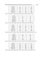
Path 2 in Example 8
No. Description 63 125 250 500 1000 2000 4000
1 Fan—Supply air, 3.3 m
3
/s, 620 Pa s.p. 92 86 80 78 78 74 71
3 560 mm wide (dia.) unlined radius elbow 0 −1 −2 −3 −3 −3 −3
Sum with noise reduction values 92 85 78 75 75 71 68
4 90° bend without turning vanes, 320 mm radius 56 54 51 47 42 37 29
Sum sound power levels 92 85 78 75 75 71 68
5 560 mm dia. by 1.12 m high pressure silencer −4 −7 −19 −31 −38 −38 −27
Sum with noise reduction values 88 78 59 44 37 33 41
6 Regenerated noise from above silencer 68 79 69 60 59 59 55
Sum sound power levels 88 82 69 60 59 59 55
7560 mm dia. by 2440 mm unlined circular duct 0000000
8 Branch pwr. div., M-560 mm dia., B-560 mm dia. −1 −1 −1 −1 −1 −1 −1
Sum with noise reduction values 87 81 68 59 58 58 54
9 Duct 90° branch takeoff, 50 mm radius 63 60 57 54 50 44 34
Sum sound power levels 87 81 68 60 59 58 54
20 560 mm dia. by 6100 mm, 26 ga. duct breakout −29 −29 −21 −11 −9 −7 −5
21 610 mm × 1.22 m × 16 mm lay-in ceiling −10 −13 −11 −14 −19 −23 −24
22 Line source—Medium-dead room −6 −5 −4 −6 −7 −8 −9
Sound pressure levels—receiver room
42 34 32 29 24 20 16
Sound pressure levels—receiver room
(without regenerated noise considered)
42 30 22 12 1 −6 2
Path 3 in Example 8
No. Description 63 125 250 500 1000 2000 4000
2 Fan—Return air, 3.3 m
3
/s, 620 Pa s.p. 82 79 80 78 78 74 71
23 810 mm wide lined square elbow w/o turning vanes −1 −6 −11 −10 −10 −10 −10
Sum with noise reduction values 81 73 69 68 68 64 61
24 90° bend w/o turning vanes; 12.7 mm radius 77 73 68 62 55 48 38
Sum sound power levels 82 76 72 69 68 64 61
25 810 mm × 1.73 m × 2.44 m lined duct −2 −2 −5 −15 −22 −11 −10
26 810 mm × 1.73 m diffuser end ref. loss −5 −2 −1 0000
21 610 mm × 1.22 m × 16 mm lay-in ceiling −10 −13 −11 −19 −19 −23 −24
27 ASHRAE room corr., 1 ind. sound source −8 −9 −10 −11 −12 −13 −14
Sound pressure levels—receiver room
57 50 45 29 15 17 13
Sound pressure levels—receiver room
(without regenerated noise considered)
56 47 42 28 15 17 13
Total Sound Pressure Levels from All Paths in Example 8
Description 63 125 250 500 1000 2000 4000
Sound pressure levels Path 1 59 53 39 34 31 28 22
Sound pressure levels Path 2 42 34 32 29 24 20 16
Sound pressure levels Path 3 57 50 45 29 15 17 13
Total sound pressure levels—All paths
61 55 46 36 32 29 23
Sound pressure levels—receiver room
(without regenerated noise considered)
61 51 42 28 15 17 14
Sound and Vibration Control 46.37
converting the sound power levels at the ceiling to corresponding
sound pressure levels in the room.
The total sound pressure levels in the receiver room from the three
paths are obtained by logarithmically adding the individual sound pres-
sure levels associated with each path. From the total sound pressure
levels for all three paths, the NC value in the room is NC 42, and the
RC value is RC 34 (R-H), which is a combination of lower frequency
rumble and higher frequency hiss.
If the regenerated noise due to airflow through the ductwork,
silencer, and diffuser are not considered, the NC value in the room is
NC 42, and the RC value is RC 26 (R-H). While the calculation proce-
dure is simplified, the typically higher-frequency regenerated noise is
not accounted for in the overall ratings especially in the RC value,
whose numeric magnitude is often set by the higher frequency noise
contribution. At a minimum, the self-noise or regenerated noise of the
silencers and outlet or inlet devices such as grilles, registers, and diffus-
ers should be considered along with the attenuation provided by the
duct elements and dynamic insertion loss of the silencers.
VIBRATION ISOLATION
AND CONTROL
Mechanical vibration and vibration-induced noise are often
major sources of occupant complaints in modern buildings. Lighter
construction in new buildings has made these buildings more sus-
ceptible to vibration and vibration-related problems. Increased
interest in energy conservation in buildings has resulted in many
new buildings being designed with variable air volume systems.
This often results in mechanical equipment being located in pent-
houses on the roof, in the use of roof-mounted HVAC units, and in
mechanical equipment rooms located on intermediate level floors.
These trends have resulted in an increase in the number of pieces of
mechanical equipment located in a building, and they often have
resulted in mechanical equipment being located adjacent to or
above occupied areas.
Occupant complaints associated with building vibration typi-
cally take one of three forms:
1. The level of vibration perceived by building occupants is of suf-
ficient magnitude to cause concern or alarm.
2. Vibration energy from mechanical equipment, which is transmit-
ted to the building structure, is transmitted to various parts of the
building and then is radiated as structure-borne noise.
3. Vibration present in a building may interfere with proper opera-
tion of sensitive equipment or instrumentation.
The following sections present basic information to properly
select and specify vibration isolators and to analyze and correct field
vibration problems. Chapter 7 in the 1997 ASHRAE Handbook—
Fundamentals and Reynolds and Bevirt (1994) provide more
detailed information.
EQUIPMENT VIBRATION
Vibration can be isolated or reduced to a fraction of the original
force with resilient mounts between the equipment and the support-
ing structure. To determine the excessive forces that must be iso-
lated or that adversely affect the performance or life of the
equipment, criteria should be established for equipment vibration.
Figures 38 and 39 show the relation between equipment vibration
levels and vibration isolators that have a fixed vibration isolation
efficiency. In this case, the magnitude of transmission to the build-
ing is a function of the magnitude of the vibration force.
VIBRATION CRITERIA
Vibration criteria can be specified relative to three areas: (1)
human response to vibration, (2) vibration levels associated
with potential damage to sensitive equipment in a building, and
(3) vibration severity of a vibrating machine. Figure 40 and
Table 43 present recommended acceptable vibration criteria for
vibration that can exist in a building structure (Ungar et al.
1990). Vibration values associated with Figure 40 are measured
by vibration transducers (usually accelerometers) that are
placed on the building structure in the vicinity of vibrating
equipment or in areas of the building that contain building
occupants or sensitive equipment. The occupant vibration crite-
ria are based on guidelines specified by ANSI Standard S3.29,
and ISO Standard 2631-2.
The manufacturer’s vibration criteria should be followed for sen-
sitive equipment. If acceptable vibration values are not available
from manufacturers, the values specified in Figure 41 can be used.
Figure 41 gives recommended equipment vibration severity ratings
based on measured RMS velocity values (IRD 1988). The vibration
values associated with Figure 41 are measured by vibration trans-
ducers (usually accelerometers) mounted directly on equipment,
equipment structures, or bearing caps. Vibration levels measured on
equipment and equipment components can be affected by unbal-
ance, misalignment of components, and resonance interaction
between a vibrating piece of equipment and the structural floor on
which it is placed. If a piece of equipment is balanced within accept-
able tolerances and excessive vibration levels still exist, the equip-
ment and its installation should be checked for possible resonant
conditions. Table 44 gives maximum allowable RMS velocity lev-
els for selected pieces of equipment.
With regard to maintenance and preventive maintenance
requirements, the vibration levels measured on equipment
structures should be in the “Good” region or below in Figure
41. Machine vibration levels in the “Fair” or “Slightly Rough”
regions may indicate potential problems. Machines with vibra-
tion levels in these regions should be monitored to ensure prob-
lems do not arise. Machine vibration levels in the “Rough” and
“Very Rough” regions indicate a potentially serious problem
exists, and immediate action should be taken to identify and
correct the problem.
SPECIFICATION OF
VIBRATION ISOLATORS
Vibration isolators must be selected to compensate for floor stiff-
ness. Longer spans also allow the structure to be more flexible, per-
mitting the building to be more easily set into vibration. Building
Fig. 38 Transmission to Structure Varies as Function
of Magnitude of Vibration Force
Fig. 39 Interrelationship of Equipment Vibration, Isolation
Efficiency, and Transmission
Sound and Vibration Control 46.39
Table 45 Selection Guide for Vibration Isolation
Equipment Type
Shaft Power, kW
and Other Rpm
Equipment Location (Note 1)
Reference
Notes
Slab on Grade
Up to 6 m
Floor Span
6- to 9 m
Floor Span
9- to 12 m
Floor Span
Base
Type
Iso-
lator
Type
Min.
Defl.,
in.
Base
Type
Iso-
lator
Type
Min.
Defl.,
in.
Base
Type
Iso-
lator
Type
Min.
Defl.,
in.
Base
Type
Iso-
lator
Type
Min.
Defl.,
in.
Refrigeration Machines and Chillers
Bare compressors All All A 2 0.25 C 3 0.75 C 3 1.75 C 4 2.50 2,3,12
Reciprocating All All A 2 0.25 A 4 0.75 A 3 1.75 A 4 2.50 2,3,12
Centrifugal All All A 1 0.25 A 4 0.75 A 3 1.75 A 3 1.75 2,3,4,12
Open centrifugal All All C 1 0.25 C 4 0.75 C 3 1.75 C 3 1.75 2,3,12
Absorption All All A 1 0.25 A 4 0.75 A 3 1.75 A 3 1.75
Air Compressors and Vacuum Pumps
Tank-mounted Up to 7.5 All A 3 0.75 A 3 0.75 A 3 1.75 A 3 1.75 3,13,15
11 and over All C 3 0.75 C 3 0.75 C 3 1.75 C 3 1.75 3,13,15
Base-mounted All All C 3 0.75 C 3 0.75 C 3 1.75 C 3 1.75 3,13,14,15
Large reciprocating All All C 3 0.75 C 3 0.75 C 3 1.75 C 3 1.75 3,13,14,15
Pumps
Closed coupled Up to 5.6 All B 2 0.25 C 3 0.75 C 3 0.75 C 3 0.75 16
7.5 and over All C 3 0.75 C 3 0.75 C 3 1.75 C 3 1.75 16
Large inline 3.7 to 19 All A 3 0.75 A 3 1.75 A 3 1.75 A 3 1.75
22 and over All A 3 1.75 A 3 1.75 A 3 1.75 A 3 2.50
End suction and split case Up to 30 All C 3 0.75 C 3 0.75 C 3 1.75 C 3 1.75 16
37 to 93 All C 3 0.75 C 3 0.75 C 3 1.75 C 3 2.50 10,16
110 and over All C 3 0.75 C 3 1.75 C 3 1.75 C 3 2.50 10,16
Cooling Towers All Up to 300 A 1 0.25 A 4 3.50 A 4 3.50 A 4 3.50 5,8,18
301 to 500 A 1 0.25 A 4 2.50 A 4 2.50 A 4 2.50 5,18
500 and over A 1 0.25 A 4 0.75 A 4 0.75 A 4 1.75 5,18
Boilers—Fire-tube All All A 1 0.25 B 4 0.75 B 4 1.75 B 4 2.50 4
Axial Fans, Fan Heads, Cabinet Fans, and Fan Sections
Up to 560 mm dia.
610 mm dia. and over
All All A 2 0.25 A 3 0.75 A 3 0.75 C 3 0.75 4,9
Up to 500 Pa s.p. Up to 300 B 3 2.50 C 3 3.50 C 3 3.50 C 3 3.50 9
300 to 500 B 3 0.75 B 3 1.75 C 3 2.50 C 3 2.50 9
501 and over B 3 0.75 B 3 1.75 B 3 1.75 B 3 1.75 9
501 Pa s.p. and
over
Up to 300 C 3 2.50 C 3 3.50 C 3 3.50 C 3 3.50 3,9
300 to 500 C 3 1.75 C 3 1.75 C 3 2.50 C 3 2.50 3,8,9
501 and over C 3 0.75 C 3 1.75 C 3 1.75 C 3 2.50 3,8,9
Centrifugal Fans
Up to 560 mm dia.
610 mm dia. and over
All All B 2 0.25 B 3 0.75 B 3 0.75 C 3 1.75 9,19
Up to 30 Up to 300 B 3 2.50 B 3 3.50 B 3 3.50 B 3 3.50 8,19
300 to 500 B 3 1.75 B 3 1.75 B 3 2.50 B 3 2.50 8,19
501 and over B 3 0.75 B 3 0.75 B 3 0.75 B 3 1.75 8,19
37 and over Up to 300 C 3 2.50 C 3 3.50 C 3 3.50 C 3 3.50 2,3,8,9,19
300 to 500 C 3 1.75 C 3 1.75 C 3 2.50 C 3 2.50 2,3,8,9,19
501 and over C 3 1.00 C 3 1.75 C 3 1.75 C 3 2.50 2,3,8,9,19
Propeller Fans
Wall-mounted All All A 1 0.25 A 1 0.25 A 1 0.25 A 1 0.25
Roof-mounted All All A 1 0.25 A 1 0.25 B 4 1.75 D 4 1.75
Heat Pumps All All A 3 0.75 A 3 0.75 A 3 0.75 A/D 3 1.75
Condensing Units All All A 1 0.25 A 4 0.75 A 4 1.75 A/D 4 1.75
Packaged AH, AC, H and V Units
All Up to 7.5 All A 3 0.75 A 3 0.75 A 3 0.75 A 3 0.75 19
11 and over,
up to 1 kPa s.p.
Up to 300 A 3 0.75 A 3 3.50 A 3 3.50 C 3 3.50 2,4,8,19
301 to 500 A 3 0.75 A 3 2.50 A 3 2.50 A 3 2.50 4,19
501 and over A 3 0.75 A 3 1.75 A 3 1.75 A 3 1.75 4,19
11 and over,
1 kPa s.p. and over
Up to 300 B 3 0.75 C 3 3.50 C 3 3.50 C 3 3.50 2,3,4,8,9
301 to 500 B 3 0.75 C 3 1.75 C 3 2.50 C 3 2.50 2,3,4,9
501 and over B 3 0.75 C 3 1.75 C 3 1.75 C 3 2.50 2,3,4,9
Packaged Rooftop Equipment All All A/D 1 0.25 D 3 0.75 ————— See Note 17 ———— 5,6,8,17
Ducted Rotating Equipment
Small fans, fan-powered
boxes
Up to 283 L/s All A 3 0.50 A 3 0.50 A 3 0.50 A 3 0.50 7
284 L/s and over All A 3 0.75 A 3 0.75 A 3 0.75 A 3 0.75 7
Engine-Driven Generators All All A 3 0.75 C 3 1.75 C 3 2.50 C 3 3.50 2,3,4
Base Types:
A. No base, isolators attached directly to equipment (Note 27)
B. Structural steel rails or base (Notes 28 and 29)
C. Concrete inertia base (Note 30)
D. Curb-mounted base (Note 31)
Isolator Types:
1. Pad, rubber, or glass fiber (Notes 20 and 21)
2. Rubber floor isolator or hanger (Notes 20 and 25)
3. Spring floor isolator or hanger (Notes 22, 23, and 25)
4. Restrained spring isolator (Notes 22 and 24)
5. Thrust restraint (Note 26)
46.40 1999 ASHRAE Applications Handbook (SI)
NOTES FOR VIBRATION ISOLATOR SELECTION GUIDE (TABLE 45)
The notes in this section are keyed to the numbers listed in the
column titled “Reference Notes” and to other reference numbers
throughout the table. While the guide is conservative, cases may
arise where vibration transmission to the building is still exces-
sive. If the problem persists after all short circuits have been elim-
inated, it can almost always be corrected by increasing isolator
deflection, using low-frequency air springs, changing operating
speed, reducing vibratory output by additional balancing or, as a
last resort, changing floor frequency by stiffening or adding more
mass.
Note 1. Isolator deflections shown are based on a floor stiffness that can
be reasonably expected for each floor span and class of equipment.
Note 2. For large equipment capable of generating substantial vibratory
forces and structure-borne noise, increase isolator deflection, if neces-
sary, so isolator stiffness is at least 0.10 times the floor stiffness.
Note 3. For noisy equipment adjoining or near noise-sensitive areas, see
the text section on Mechanical Equipment Room Sound Isolation.
Note 4. Certain designs cannot be installed directly on individual isola-
tors (Type A), and the equipment manufacturer or a vibration spe-
cialist should be consulted on the need for supplemental support
(Base Type).
Note 5. Wind load conditions must be considered. Restraint can be
achieved with restrained spring isolators (Type 4), supplemental brac-
ing, or limit stops.
Note 6. Certain types of equipment require a curb-mounted base (Type
D). Airborne noise must be considered.
Note 7. See the text section on Resilient Pipe Hangers and Supports for
hanger locations adjoining equipment and in equipment rooms.
Note 8. To avoid isolator resonance problems, select isolator deflection
so that resonant frequency is 40% or less of the lowest operating speed
of equipment.
Note 9. To limit undesirable movement, thrust restraints (Type 5) are
required for all ceiling-suspended and floor-mounted units operating at
50 mm and more total static pressure.
Note 10. Pumps over 55 kW may require extra mass and restraining
devices.
Isolation for Specific Equipment
Note 12. Refrigeration Machines: Large centrifugal, hermetic, and
reciprocating refrigeration machines generate very high noise levels,
and special attention is required when such equipment is installed in
upper stories or near noise-sensitive areas. If such equipment is to be
located near extremely noise-sensitive areas, confer with an acousti-
cal consultant.
Note 13. Compressors: The two basic reciprocating compressors are (1)
single- and double-cylinder vertical, horizontal or L-head, which are
usually air compressors; and (2) Y, W, and multihead or multicylinder
air and refrigeration compressors. Single- and double-cylinder com-
pressors generate high vibratory forces requiring large inertia bases
(Type C) and are generally not suitable for upper-story locations. If
such equipment must be installed in upper stories or on grade locations
near noise-sensitive areas, unbalanced forces should be obtained from
the equipment manufacturer, and a vibration specialist should be con-
sulted for design of the isolation system.
Note 14. Compressors: When using Y, W, and multihead and multicylin-
der compressors, obtain the magnitude of unbalanced forces from the
equipment manufacturer so that the necessity for an inertia base can be
evaluated.
Note 15. Compressors: Base-mounted compressors through 4 kW and
horizontal tank-type air compressors through 8 kW can be installed
directly on spring isolators (Type 3) with structural bases (Type B) if
required, and compressors 10 to 75 kW on spring isolators (Type 3)
with inertia bases (Type C) with a mass of one to two times the com-
pressor mass.
Note 16. Pumps: Concrete inertia bases (Type C) are preferred for all
flexible-coupled pumps and are desirable for most close-coupled
pumps, although steel bases (Type B) can be used. Close-coupled
pumps should not be installed directly on individual isolators (Type A)
because the impeller usually overhangs the motor support base, caus-
ing the rear mounting to be in tension. The primary requirements for
Type C bases are strength and shape to accommodate base elbow sup-
ports. Mass is not usually a factor, except for pumps over 55 kW where
extra mass helps limit excess movement due to starting torque and
forces. Concrete bases (Type C) should be designed for a thickness of
one-tenth the longest dimension with minimum thickness as follows:
(1) for up to 20 kW, 150 mm; (2) for 30 to 55 kW, 200 mm; and (3) for
75 kW and higher, 300 mm.
Pumps over 55 kW and multistage pumps may exhibit excessive
motion at start-up; supplemental restraining devices can be installed
if necessary. Pumps over 90 kW may generate high starting forces,
so a vibration specialist should be consulted for installation recom-
mendations.
Note 17. Packaged Rooftop Air-Conditioning Equipment: This equip-
ment is usually on light structures that are susceptible to sound and
vibration transmission. The noise problem is further compounded by
curb-mounted equipment, which requires large roof openings for sup-
ply and return air.
The table shows Type D vibration isolator selections for all spans
up to 6 m, but extreme care must be taken for equipment located on
spans of over 6 m, especially if construction is open web joists or
thin low-density slabs. The recommended procedure is to determine
the additional deflection caused by equipment in the roof. If addi-
tional roof deflection is 6 mm or under, the isolator can be selected
for 15 times the additional roof deflection. If additional roof deflec-
tion is over 6 mm, supplemental stiffening should be installed or the
unit should be relocated.
For units, especially large units, capable of generating high noise
levels, consider (1) mounting the unit on a platform above the roof
deck to provide an air gap (buffer zone) and (2) locating the unit away
from the roof penetration, thus permitting acoustical treatment of ducts
before they enter the building.
Some rooftop equipment has compressors, fans, and other equip-
ment isolated internally. This isolation is not always reliable because
of internal short circuiting, inadequate static deflection, or panel reso-
nances. It is recommended that rooftop equipment be isolated exter-
nally, as if internal isolation were not used.
Note 18. Cooling Towers: These are normally isolated with restrained
spring isolators (Type 4) directly under the tower or tower dunnage.
Occasionally, high deflection isolators are proposed for use directly
under the motor-fan assembly, but this arrangement must be used with
extreme caution.
Note 19. Fans and Air-Handling Equipment: The following should be
considered in selecting isolation systems for fans and air-handling
equipment:
Fans with wheel diameters of 560 mm and under and all fans operat-
ing at speeds to 300 rpm do not generate large vibratory forces. For
fans operating under 300 rpm, select isolator deflection so that the iso-
lator natural frequency is 40% or less of the fan speed. For example,
for a fan operating at 275 rpm, an isolator natural frequency of 110
rpm (1.8 Hz) or lower is required (0.4 × 275 = 110 rpm). A 75-mm
deflection isolator (Type 3) can provide this isolation.
Flexible duct connectors should be installed at the intake and dis-
charge of all fans and air-handling equipment to reduce vibration
transmission to air ducts.
Inertia bases (Type C) are recommended for all Class 2 and 3 fans
and air-handling equipment because extra mass permits the use of
stiffer springs, which limit movement.
Thrust restraints (Type 5) that incorporate the same deflection as
isolators should be used for all fan heads, all suspended fans, and all
base-mounted and suspended air-handling equipment operating at 500
Pa and over total static pressure.
Vibration Isolators:
Materials, Types, and Configurations
Notes 20 through 31 are useful for evaluating commercially
available isolators for HVAC equipment. The isolator selected for
a particular application depends on the required deflection, but life,
cost, and suitability must also be considered.
Sound and Vibration Control 46.41
Note 20. Rubber isolators are available in pad (Type 1) and molded (Type 2) configurations.
Pads are used in single or multiple layers. Molded isolators come in a range of 30 to 70 durom-
eter (a measure of stiffness). Material in excess of 70 durometer is usually ineffective as an iso-
lator. Isolators are designed for up to 13-mm deflection, but are used where 8-mm or less
deflection is required. Solid rubber and composite fabric and rubber pads are also available.
They provide high load capacities with small deflection and are used as noise barriers under
columns and for pipe supports. These pad types work well only when they are properly loaded
and the weight load is evenly distributed over the entire pad surface. Metal loading plates can
be used for this purpose.
Note 21. Precompressed glass fiber isolation pads (Type 1) constitute inorganic inert material and
are available in various sizes in thicknesses of 25 to 100 mm, and in capacities of up to 3.4 MPa.
Their manufacturing process assures long life and a constant natural frequency of 7 to 15 Hz over
the entire recommended load range. Pads are covered with an elastomeric coating to increase
damping and to protect the glass fiber. Glass fiber pads are most often used for the isolation of
concrete foundations and floating floor construction.
Note 22. Steel springs are the most popular and versatile isolators for HVAC applications because
they are available for almost any deflection and have a virtually unlimited life. All spring isola-
tors should have a rubber acoustical barrier to reduce transmission of high-frequency vibration
and noise that can migrate down the steel spring coil. They should be corrosion-protected if
installed outdoors or in a corrosive environment. The basic types include
1. Note 23. Open spring isolators (Type 3) consist of a top and bottom load plate with an
adjustment bolt for leveling. Springs should be designed with a horizontal stiffness at least 100%
of the vertical stiffness to assure stability, 50% travel beyond rated load and safe solid stresses.
2. Note 24. Restrained spring isolators (Type 4) have hold-down bolts to limit vertical move-
ment. They are used with (a) equipment with large variations in mass (boilers, refrigeration
machines) to restrict movement and prevent strain on piping when water is removed, and (b) out-
door equipment, such as cooling towers, to prevent excessive movement because of wind load.
Spring criteria should be the same as for open spring isolators, and restraints should have ade-
quate clearance so that they are activated only when a temporary restraint is needed.
3. Housed spring isolators consist of two telescoping housings separated by a resilient mate-
rial. Depending on design and installation, housed spring isolators can bind and short circuit.
Their use should be avoided.
Air springs can be designed for any frequency but are economical only in applications with natu-
ral frequencies of 1.33 Hz or less (150-mm or greater deflection). Their use is advantageous in
that they do not transmit high-frequency noise and are often used to replace high deflection
springs on problem jobs. Constant air supply is required, and there should be an air dryer in the
air supply.
Note 25. Isolation hangers (Types 2 and 3) are used for suspended pipe and equipment and have
rubber, springs, or a combination of spring and rubber elements. Criteria should be the same as
for open spring isolators. To avoid short circuiting, hangers should be designed for 20 to 35°
angular hanger rod misalignment. Swivel or traveler arrangements may be necessary for connec-
tions to piping systems subject to large thermal movements.
Note 26. Thrust restraints (Type 5) are similar to spring hangers or isolators and are installed in
pairs to resist the thrust caused by air pressure.
DIRECT ISOLATION (Type A)
Note 27. Direct isolation (Type A) is used when equipment is unitary and rigid and does not
require additional support. Direct isolation can be used with large chillers, packaged air-handling
units, and air-cooled condensers. If there is any doubt that the equipment can be supported
directly on isolators, use structural bases (Type B) or inertia bases (Type C), or consult the equip-
ment manufacturer.
46.42 1999 ASHRAE Applications Handbook (SI)
The following approach is suggested to develop isolator selec-
tions for specific applications:
1. Use Table 45 for floors specifically designed to accommodate
mechanical equipment.
2. Use recommendations for the 6 m span column for equipment on
ground-supported slabs adjacent to noise-sensitive areas.
3. For roofs and floors constructed with open web joists, thin long
span slabs, wooden construction, and any unusual light construc-
tion, evaluate all equipment with a mass of more than 140 kg to
determine the additional deflection of the structure caused by the
equipment. Isolator deflection should be 15 times the additional
deflection or the deflection shown in Table 45, whichever is
greater. If the required spring isolator deflection exceeds com-
mercially available products, consider air springs, stiffen the
supporting structure, or change the equipment location.
4. When mechanical equipment is adjacent to noise-sensitive areas,
isolate mechanical equipment room noise.
ISOLATION OF VIBRATION AND
NOISE IN PIPING SYSTEMS
All piping has mechanical vibration generated by the equip-
ment and impeller-generated and flow-induced vibration and
noise, which is transmitted by the pipe wall and the water column.
In addition, equipment installed on vibration isolators exhibits
some motion or movement from pressure thrusts during operation.
Vibration isolators have even greater movement during start-up
and shutdown, when the equipment goes through the isolators’
resonant frequency. The piping system must be flexible enough to
(1) reduce vibration transmission along the connected piping, (2)
permit equipment movement without reducing the performance of
vibration isolators, and (3) accommodate equipment movement or
thermal movement of the piping at connections without imposing
undue strain on the connections and equipment.
Flow noise in piping can be minimized by sizing pipe so that
the velocity is 1.2 m/s maximum for pipe 50 mm and smaller and
using a pressure drop limitation of 400 Pa per metre of pipe length
with a maximum velocity of 3 m/s for larger pipe sizes. Flow noise
and vibration can be reintroduced by turbulence, sharp pressure
drops, and entrained air. Care should be taken to avoid these
conditions.
Resilient Pipe Hangers and Supports
Resilient pipe hangers and supports are necessary to prevent
vibration and noise transmission from the piping to the building
structure and to provide flexibility in the piping.
Note 28. Structural bases (Type B) are used where equipment cannot be supported at individual
locations and/or where some means is necessary to maintain alignment of component parts in
equipment. These bases can be used with spring or rubber isolators (Types 2 and 3) and should
have enough rigidity to resist all starting and operating forces without supplemental hold-down
devices. Bases are made in rectangular configurations using structural members with a depth
equal to one-tenth the longest span between isolators, with a minimum depth of 100 mm. Max-
imum depth is limited to 300 mm, except where structural or alignment considerations dictate
otherwise.
Note 29. Structural rails (Type B) are used to support equipment that does not require a unitary
base or where the isolators are outside the equipment and the rails act as a cradle. Structural rails
can be used with spring or rubber isolators and should be rigid enough to support the equipment
without flexing. Usual industry practice is to use structural members with a depth one-tenth of the
longest span between isolators with a minimum depth of 100 mm. Maximum depth is limited to
300 mm, except where structural considerations dictate otherwise.
Note 30. Concrete bases (Type C) consist of a steel pouring form usually with welded-in reinforc-
ing bars, provision for equipment hold-down, and isolator brackets. Like structural bases, con-
crete bases should be rectangular or T-shaped and, for rigidity, have a depth equal to one-tenth the
longest span between isolators, with a minimum of 150 mm. Base depth need not exceed 300 mm
unless it is specifically required for mass, rigidity, or component alignment.
Note 31. Curb isolation systems (Type D) are specifically designed for curb-supported rooftop
equipment and have spring isolation with a watertight and airtight curb assembly. The roof curbs
are narrow to accommodate the small diameter of the springs within the rails, with static deflec-
tion in the 25- to 75 mm range to meet the design criteria described for Type 3.
Sound and Vibration Control 46.43
Suspended Piping. Isolation hangers described in the vibration
isolation section should be used for all piping in equipment rooms or
for 15 m from vibrating equipment, whichever is greater. To avoid
reducing the effectiveness of equipment isolators, at least the first
three hangers from the equipment should provide the same deflec-
tion as the equipment isolators, with a maximum limitation of
50 mm deflection; the remaining hangers should be spring or combi-
nation spring and rubber with 20 mm deflection.
Good practice requires the first two hangers adjacent to the
equipment to be the positioning or precompressed type, to prevent
load transfer to the equipment flanges when the piping is filled. The
positioning hanger aids in installing large pipe, and many engineers
specify this type for all isolated pipe hangers for piping 200 mm and
over.
While isolation hangers are not often specified for branch piping
or piping beyond the equipment room for economic reasons, they
should be used for all piping over 50 mm in diameter and for any
piping suspended below or near noise-sensitive areas. Hangers adja-
cent to noise-sensitive areas should be the spring and rubber com-
bination Type 3.
Floor Supported Piping. Floor supports for piping in equip-
ment rooms and adjacent to isolated equipment should use vibration
isolators as described in the vibration isolation section. They should
be selected according to the guidelines for hangers. The first two
adjacent floor supports should be the restrained spring type, with a
blocking feature that prevents load transfer to equipment flanges as
the piping is filled or drained. Where pipe is subjected to large ther-
mal movement, a slide plate (PTFE, graphite, or steel) should be
installed on top of the isolator, and a thermal barrier should be used
when rubber products are installed directly beneath steam or hot
water lines.
Riser Supports, Anchors, and Guides. Many piping systems
have anchors and guides, especially in the risers, to permit expan-
sion joints, bends, or pipe loops to function properly. Anchors and
guides eliminate or limit (guide) pipe movement, but must be rig-
idly attached to the structure; this is inconsistent with the resiliency
required for effective isolation. The engineer should try to locate the
pipe shafts, anchors, and guides in noncritical areas, such as next to
elevator shafts, stairwells, and toilets, rather than adjoining noise-
sensitive areas. Where concern about vibration transmission exists,
some type of vibration isolation support or acoustical support is
required for the pipe support, anchors, and guides.
Because anchors or guides must be rigidly attached to the struc-
ture, the isolator cannot deflect in the sense previously discussed,
and the primary interest is to create an acoustical barrier. Such
acoustical barriers can be provided by heavy-duty rubber and duck
and rubber pads that can accommodate large loads with minimal
deflection. Figure 42 shows some arrangements for resilient
anchors and guides. Similar resilient-type supports can be used for
the pipe.
Resilient supports for pipe, anchors, and guides can attenuate
noise transmission, but they do not provide the resiliency required
to isolate vibration. Vibration must be controlled in an anchor guide
by designing flexible pipe connectors and resilient isolation hangers
or supports.
Completely spring-isolated risers that eliminate the anchors and
guides have been used successfully in many instances and give
effective vibration and acoustical isolation. In this type of isolation,
the springs are sized to accommodate thermal growth as well as to
guide and support the pipe. Such systems require careful engineer-
ing to accommodate the movements encountered not only in the
riser but also in the branch takeoff to avoid overstressing the piping.
Piping Penetrations. Most HVAC systems have many points at
which piping must penetrate floors, walls, and ceilings. If such pen-
etrations are not properly treated, they provide a path for airborne
noise, which can destroy the acoustical integrity of the occupied
space. Seal the openings in the pipe sleeves between noisy areas,
such as equipment rooms, and occupied spaces with an acoustical
barrier such as fibrous material and caulking or with engineered
pipe penetration seals as shown in Figure 43.
Flexible Pipe Connectors
Flexible pipe connectors (1) provide piping flexibility to permit
isolators to function properly, (2) protect equipment from strain
from misalignment and expansion or contraction of piping, and (3)
Fig. 42 Resilient Anchors and Guides for Pipes
Fig. 43 Acoustical Pipe Penetration Seals
46.44 1999 ASHRAE Applications Handbook (SI)
attenuate noise and vibration transmission along the piping (Figure
44). Connectors are available in two configurations: (1) hose type,
a straight or slightly corrugated wall construction of either rubber or
metal; and (2) the arched or expansion joint type, a short length con-
nector with one or more large radius arches, of rubber, Teflon, or
metal. Metal expansion joints are seldom used for vibration and
sound isolation in HVAC work, and their use is not recommended.
All flexible connectors require end restraint to counteract the pres-
sure thrust, which is (1) added to the connector, (2) incorporated by
its design, (3) added to the piping (anchoring), or (4) built in by the
stiffness of the system. Connector extension caused by pressure
thrust on isolated equipment should also be considered when flexi-
ble connectors are used. Overextension will cause failure. Manufac-
turers’ recommendations on restraint, pressure, and temperature
limitations should be strictly adhered to.
Hose Connectors
Hose connectors accommodate lateral movement perpendicular
to the length and have very limited or no axial movement capability.
Rubber hose connectors can be of molded or handwrapped con-
struction with wire reinforcing. They are available with metal-
threaded end fittings or integral rubber flanges. Threaded fittings
should be limited to 80 mm and smaller pipe diameter. The fittings
should be the mechanically expanded type to minimize the possibil-
ity of pressure thrust blowout. Flanged types are available in larger
pipe sizes. Table 46 lists recommended lengths.
Metal hose is constructed with a corrugated inner core and a
braided cover, which helps attain a pressure rating and provides end
restraints that eliminate the need for supplemental control assem-
blies. Short lengths of metal hose or corrugated metal bellows, or
pump connectors, are available without braid and have built-in con-
trol assemblies. Metal hose is used to control misalignment and
vibration rather than noise and is used primarily where temperature
or the pressure of flow media precludes the use of other material.
Table 46 provides recommended lengths.
Expansion Joint or Arched-Type Connectors
Expansion joint or arched-type connectors have one or more
convolutions or arches and can accommodate all modes of axial, lat-
eral, and angular movement and misalignment. These connectors
are available in flanged rubber and PTFE (Teflon) construction.
PTFE expansion joints and couplings are similar in construction to
rubber expansion joints with reinforcing metal rings. When made of
rubber, they are commonly called expansion joints, spool joints, or
spherical connectors, and in PTFE, as couplings or expansion joints.
Rubber expansion joints or spool joints are available in two basic
types: (1) handwrapped with wire and fabric reinforcing, and (2)
molded with fabric and wire or with high-strength fabric only
(instead of metal) for reinforcing. The handmade joint is available
in a variety of materials and lengths for special applications. Rubber
spherical connectors are molded with high-strength fabric or tire
cord reinforcing instead of metal. Their distinguishing characteris-
tic is a large radius arch. The shape and construction of some
designs permit use without control assemblies in systems operating
to 1 MPa. Where thrust restraints are not built in, they must be used
as described for rubber hose joints.
In evaluating these devices, temperature, pressure, and service
conditions must be considered as well as the ability of each device
to attenuate vibration and noise. Metal hose connections can accom-
modate misalignment and attenuate mechanical vibration transmit-
ted through the pipe wall but do little to attenuate noise. This type of
connector has superior resistance to long-term temperature effects.
Rubber hose, expansion joints, and spherical connectors attenu-
ate vibration and impeller-generated noise transmitted through the
pipe wall. Because the rubber expansion joint and spherical connec-
tor walls are flexible, they have the ability to grow volumetrically
and attenuate noise and vibration at blade passage frequencies. This
feature is particularly desirable for uninsulated piping, such as con-
denser water and domestic water, which may run adjacent to noise-
sensitive areas. However, high pressure has a detrimental effect on
the ability of the connector to attenuate vibration and noise.
Because none of the flexible pipe connectors control flow or
velocity noise or completely isolate vibration and noise transmis-
sion to the piping, resilient pipe hangers and supports should be
used; these are shown in Note 25, Table 45 and are described in the
Resilient Pipe Hangers and Supports section.
ISOLATING DUCT VIBRATION
Flexible canvas and rubber duct connections should be used at
fan intake and discharge. However, they are not completely effec-
tive since they become rigid under pressure and allow the vibrating
fan to pull on the duct wall. To maintain a slack position of the flex-
ible duct connections, thrust restraints (see note 26, Table 45)
should be used on all equipment.
While vibration transmission from ducts isolated by flexible
connectors is not a common problem, flow pulsations in the duct
can cause vibration in the duct walls, which can be transmitted
through rigid hangers. Spring or combination spring and rubber
hangers should be used on ducts suspended below or near a noise-
sensitive area. These hangers are especially recommended for large
ducts with a velocity above 7.5 m/s and for all size ducts when duct
static pressure is 500 Pa and over.
Table 46 Recommended Live Length
a
of Flexible Rubber
and Metal Hose
Nominal
Diameter, mm Length,
b
mm
Nominal
Diameter, mm Length,
b
mm
20 300 100 450
25 300 125 600
40 300 150 600
50 300 200 600
65 300 250 600
80 450 300 900
a
Live length is end-to-end length for integral flanged rubber hose and is end-to-end
less total fitting length for all other types.
b
Based on recommendations of Rubber Expansion Division, Fluid Sealing Association.
Fig. 44 Flexible Pipe Connectors
Sound and Vibration Control 46.45
SEISMIC PROTECTION
Seismic restraint requirements are specified by applicable build-
ing codes that define the design forces to be resisted by the mechan-
ical system, depending on the building location and occupancy,
location of the system in the building, and whether it is used for life
safety. Where required, seismic protection of resiliently mounted
equipment poses a unique problem, because resiliently mounted
systems are much more susceptible to earthquake damage due to
overturning forces and to resonances inherent in vibration isolators.
As a deficiency in seismic restraint design or anchorage would
not become apparent until an earthquake occurs, with possible cat-
astrophic consequences, the adequacy of the restraints and anchor-
age to resist design forces must be verified before the event. This
verification should be either by equipment tests, calculations, or
dynamic analysis, depending on the item; with calculations or
dynamic analysis performed under the direction of a professional
engineer. These items are often supplied as a package by the vibra-
tion isolation vendor.
The restraints for floor-mounted equipment should have ade-
quate clearances so that they are not engaged during normal opera-
tion of the equipment. Contact surfaces should be protected with
resilient pads to limit shock during an earthquake, and restraints
should be sufficiently strong to resist forces in any direction. The
integrity of these devices can be verified by a comprehensive anal-
ysis but is more frequently verified by laboratory tests.
Calculations or dynamic analysis should have an engineer’s seal
to verify that input forces are obtained in accordance with code or
specification requirements. The anchorage calculations should also
be made by a professional engineer in accordance with accepted
standards. Chapter 53, Seismic and Wind Restraint Design, has
more information on this topic.
VIBRATION INVESTIGATIONS
Theoretically, a vibration isolation system can be selected to iso-
late vibration forces of extreme magnitude. However, isolators
should not be used to mask a condition that should be corrected
before it damages the equipment and its operation. High transmitted
vibration levels can indicate a faulty equipment operating condition
in need of correction or they can be a symptom of a resonance inter-
action between a vibrating piece of equipment and the structural
floor on which it is placed.
Vibration investigations should include
• Measurement of the imbalance of reciprocating or rotating equip-
ment components.
• Measurement of the vibration levels on vibrating equipment.
Refer to Figure 41 for recommended vibration severity ratings of
vibrating equipment.
• Measurement of vibration levels in building structures on which
vibrating equipment is placed. Refer to Figure 40 and Table 43 for
recommended building vibration criteria.
• Examination of equipment vibration generated by components,
such as bearings, drives, etc.
• Examination of equipment installation factors, such as equipment
alignment, vibration isolator placement, etc. Refer to Table 45.
TROUBLESHOOTING
In spite of the efforts taken by specifying engineers, consultants,
and installing contractors, some situations arise that have disturbing
noise and vibration. Fortunately, many problems can be readily
identified and corrected by
• Determining which equipment or system is the problem source
• Determining if the problem is one of airborne sound, vibration
and structure-borne noise, or a combination of both
• Applying appropriate solutions
Troubleshooting is time-consuming, expensive, and often diffi-
cult. In addition, once a transmission problem exists, the occupants
become more sensitive and require greater reduction of the sound
and vibration levels than would initially have been satisfactory.
Therefore, the need for troubleshooting should be avoided by care-
fully designing, installing, and testing the system as soon as it is
operational and before the building is occupied.
DETERMINING PROBLEM SOURCE
The system or equipment that is the source of the problem can
often be determined without instrumentation. Vibration and noise
levels are usually well above the sensory level of perception and are
readily felt or heard. A simple and accurate method of determining
the problem source is to turn individual pieces of equipment on and
off until the vibration or noise is eliminated. Since the source of the
problem is often more than one piece of equipment or the interaction
of two or more systems, it is good practice to double check by shut-
ting off the system and operating the equipment individually. Rey-
nolds and Bevirt (1994) provides information relative to the
measurement and assessment of sound and vibration in buildings.
DETERMINING PROBLEM TYPE
The next step is to determine if the problem is one of noise or
vibration.
1. If vibration is perceptible, vibration transmission is usually the
major cause of the problem. The possibility that lightweight wall
or ceiling panels are excited by airborne noise should be consid-
ered. If vibration is not perceptible, the problem may still be one
of vibration transmission causing structure-borne noise, which
can be checked by following the procedure below.
2. If a sound level meter is available, check C-weighted and overall
readings. If the difference is greater than 6 dB, or if the slope of
the curve is greater than 5 to 6 dB per octave in the low frequen-
cies, vibration is probably the cause.
3. If the affected area is remote from the source equipment, no
problem is apparent in intermediary spaces, and noise does not
appear to be coming from the duct system or diffusers, structure-
borne noise is the probable cause.
Noise Problems
Noise problems are more complex than vibration problems and
usually require the services of an acoustical engineer or consultant.
If the affected area adjoins the room where the source equipment is
located, structure-borne noise must be considered as part of the
problem, and the vibration isolation should be checked. A simple
but reasonably effective test is to have one person listen in the
affected area while another shouts loudly in the equipment room. If
the voice cannot be heard, the problem is likely one of structure-
borne noise. If the voice can be heard, check for openings in the wall
or floor separating the areas. If no such openings exist, the structure
separating the areas does not provide adequate transmission loss. In
such situations, refer to the Mechanical Equipment Room Sound
Isolation section of this chapter for possible solutions.
If ductborne sound, i.e. noise from grilles or diffusers or duct
breakout noise, is the problem, measure the sound pressure levels
and compare them with the design goal RC curves. Where the mea-
sured curve differs from the design goal RC curve, the potential
noise source(s) can be identified. Once the noise sources have been
identified, the engineer can determine whether sufficient attenua-
tion has been provided by analyzing each sound source using the
procedures presented in this chapter.
If the sound source is a fan, pump, or similar rotating equipment,
determine if it is operating at the most efficient part of its operating
curve. Excessive vibration and noise can occur if a fan or pump is
trying to move too little or too much air or water. In this respect,
46.46 1999 ASHRAE Applications Handbook (SI)
check that vanes, dampers, and valves are in the correct operating
position and that the system has been properly balanced.
Vibration Problems
Vibration and structure-borne noise problems can occur from
• Equipment operating with excessive levels of vibration, usually
caused by unbalance
• Lack of vibration isolators
• Improperly selected or installed vibration isolators that do not
provide the required isolator deflection
• Flanking transmission paths such as rigid pipe connections or
obstructions under the base of vibration-isolated equipment
• Floor flexibility
• Resonances in equipment, the vibration isolation, or the building
structure
Most field-encountered problems are the result of improperly
selected or installed isolators and flanking paths of transmission,
which can be simply evaluated and corrected. Floor flexibility and
resonance problems are sometimes encountered and usually require
analysis by experts. However, the information provided below will
identify such problems. If the equipment lacks vibration isolators,
isolators recommended in Table 45 can be added by using structural
brackets without altering connected ducts or piping.
Testing Vibration Isolation. Improperly functioning vibration
isolation is the cause of most field-encountered problems and can be
evaluated and corrected by the following procedures.
1. Ensure that the system is free-floating by bouncing the base,
which should cause the equipment to move up and down freely
and easily. On floor-mounted equipment, check that there are no
obstructions between the base and the floor that would short cir-
cuit the isolation system. This check is best accomplished by
passing a rod under the equipment. A small obstruction might
permit the base to rock, giving the impression that it is free-float-
ing when it is not. On suspended equipment, make sure that rods
are not touching the hanger box. Rigid connections such as pipes
and ducts can prevent equipment from floating freely, prohibit
isolators from functioning properly, and provide flanking paths
for the transmission of vibration.
2. Determine if the isolator deflection is as specified or required,
changing it if necessary, as recommended in Table 45. A com-
mon problem is inadequate deflection caused by underloaded
isolators. Overloaded isolators are not generally a problem as
long as the system is free floating and there is space between the
spring coils.
With the most spring isolators, determine the spring deflection
by measuring the operating height and comparing it to the free
height information available from the manufacturer. Once the actual
isolator deflection is known, determine its adequacy by comparing
it with the recommended deflection in Table 45.
If the natural frequency of the isolator is 25% or less than the dis-
turbing frequency (usually considered the operating speed of the
equipment), the isolators should be amply efficient except for heavy
equipment installed on extremely long span floors or very flexible
floors. If a transmission problem exists, it may be caused by (1)
excessively rough equipment operation, (2) the system not being
free floating or flanking path transmission, or (3) a resonance or
floor stiffness problem, as described below.
While it is easy to determine the natural frequency of spring iso-
lators by height measurements, such measurements are difficult
with pad and rubber isolators and are not accurate in determining
their natural frequencies. Although such isolators can theoretically
provide natural frequencies as low as 4 Hz, they actually provide
higher natural frequencies and generally do not provide the desired
isolation efficiencies for upper floor equipment locations.
Generally, vibration isolation efficiency can not be determined in
field installations by field vibration measurements. However, vibra-
tion measurements can be made on vibrating equipment, on equip-
ment supports, on floors supporting vibration-isolated equipment,
and on floors in adjacent areas to determine if vibration criteria
specified in Table 43 or in Figures 40 and 41 have been achieved in
field installations.
Floor Flexibility Problems. Floor flexibility is not a problem
with most equipment and structures; however, such problems can
occur with heavy equipment installed on long span floors or on
thin slabs and with rooftop equipment installed on light struc-
tures with open web joist construction. If floor flexibility is sus-
pected, the isolators should be one-tenth or less as stiff as the
floor to eliminate the problem. Floor stiffness can be determined
by calculating the additional deflection in the floor caused by a
specific piece of equipment.
For example, if a 5000 kg piece of equipment causes floor deflec-
tion of an additional 2.5 mm, floor stiffness is 19.6 MN/m (2 Gg/m),
and an isolator combined stiffness of 1.96 MN/m or less must be
used. Note that the floor stiffness or spring rate, not the total floor
deflection, is determined. In this example, the total floor deflection
might be 25 mm, but if the problem equipment causes 2.5 mm of
that deflection, 2.5 mm is the important figure, and floor stiffness k
is 19.6 MN/m.
Resonance Problems. These problems occur when the operat-
ing speed of the equipment is the same as or close to the resonant
frequency of (1) an equipment component such as a fan shaft or
bearing support pedestal, (2) the vibration isolation, or (3) the reso-
nant frequency of the floor or other building component, such as a
wall. Vibration resonances can cause excessive equipment vibration
levels, as well as objectionable and possibly destructive vibration
transmission in a building. These conditions must always be identi-
fied and corrected.
When vibrating mechanical equipment is mounted on vibration
isolators on a flexible floor, there are two resonance frequencies that
must be considered. The lower frequency is associated with and pri-
marily controlled by the stiffness (and consequently the static
deflection) of the vibration isolators. This frequency is generally
significantly less than the operating speed (or frequency) of the
mechanical equipment and is generally not a problem. The higher
resonant frequency is associated with and primarily controlled by
the stiffness of the floor. This resonant frequency is usually not
affected by increasing or decreasing the static deflection of the
mechanical equipment vibration isolators. Sometimes when the
floor on which mechanical equipment is located is flexible (occurs
with some long-span floors and with roofs supporting rooftop pack-
aged units) the operating speed of the mechanical equipment can
coincide with the higher resonant frequency. When this occurs,
changing the static deflection of the vibration isolators will not
solve the problem.
Vibration Isolation Resonance. Always characterized by
excessive equipment vibration, vibration isolation resonance usu-
ally results in objectionable transmission to the structure. However,
transmission might not occur if the equipment is on-grade or on a
stiff floor. Vibration isolation resonance can be measured with
instrumentation or, more simply, by determining the isolator natural
frequency as described in the section Testing Vibration Isolation
and comparing this figure to the operating speed of the equipment.
When vibration isolation resonance exists, the isolator natural
frequency must be changed using the following guidelines:
1. If the equipment is installed on pad or rubber isolators, isolators
with the deflection recommended in Table 45 should be
installed.
2. If the equipment is installed on spring isolators and there is
objectionable vibration or noise transmission to the structure,
determine if the isolator is providing maximum deflection. For
Sound and Vibration Control 46.47
example, an improperly selected or installed nominal 50 mm
deflection isolator could be providing only 3 mm deflection,
which would be in resonance with equipment operating at 500
rpm. If this is the case, the isolators should be replaced with ones
having enough capacity to provide 50 mm deflection. Since there
was no transmission problem with the resonant isolators, it is not
necessary to use greater deflection isolators than can be conve-
niently installed.
3. If the equipment is installed on spring isolators and there is
objectionable noise or vibration transmission, replace the isola-
tors with spring isolators with the deflection recommended in
Table 45.
Building Resonances. These problems occur when some part of
the structure has a resonant frequency the same as the disturbing fre-
quency or the operating speed of some of the equipment. These
problems can exist even if the isolator deflections recommended in
Table 45 are used. The resulting objectionable noise or vibration
should be evaluated and corrected. Often, the resonant problem is in
the floor on which the equipment is installed, but it can also occur
in a remotely located floor, wall, or other building component. If a
noise or vibration problem has a remote source which cannot be
associated with piping or ducts, resonance must be suspected.
Building resonance problems can be resolved by the following:
1. Reduce the vibration force by balancing the equipment. This is
not a practical solution for a true resonant problem; however, it
is viable when the disturbing frequency equals the floor natural
frequency, as evidenced by the equal displacement of the floor
and the equipment, especially when the equipment is operating
with excessive vibration.
2. Change the isolator resonant frequency by increasing or decreas-
ing the static deflection of the isolator. Only small changes are
necessary to “detune” the system. Generally, increasing the
deflections is preferred. If the initial deflection is 25 mm, a 50 or
75 mm deflection isolator should be installed. However, if the
initial isolator deflection is 100 mm, it may be more practical and
economical to replace it with a 75 or 50 mm deflection isolator.
3. Change the structure stiffness or the structure resonant fre-
quency. A change in structure stiffness changes the structure res-
onant frequency. The greater the stiffness, the higher the
resonant frequency. However, the structure resonant frequency
can also be changed by increasing or decreasing the floor deflec-
tion without changing the floor stiffness. While this approach is
not recommended, it may be the only solution in certain cases.
4. Change the disturbing frequency by changing the equipment
operating speed. This is practical only for belt-driven equipment,
or equipment driven by variable frequency drives.
STANDARDS
AMCA 300. Reverberant Room Method for Sound Testing of Fans.
ANSI S3.29. 1983 (Reviewed 1990). Guide to Evaluation of Human Expo-
sure to Vibration in Buildings.
ANSI S12.2. 1995. Criteria for Evaluating Room Noise.
ANSI S12.31. 1990. Precision Methods for the Determination of Sound
Power Levels of Broad-Band Noise Sources in Reverberation Rooms.
ANSI S12.32. 1990. Precision Methods for the Determination of Sound
Power Levels of Discrete-Frequency and Narrow-Band Noise Sources in
Reverberation Rooms.
ANSI S12.34. 1988. Engineering Methods for the Determination of Sound
Power Levels of Noise Sources for Essentially Free-Field Conditions
over a Reflecting Plane.
ARI 270. 1995. Sound Rating of Outdoor Unitary Equipment.
ARI 275. 1997. Application of Sound Rating Levels of Outdoor Unitary
Equipment.
ARI 300.1988. Rating the Sound Level and Transmission Loss of Packaged
Terminal Equipment.
ARI 350. 1986. Sound Rating of Non-Ducted Indoor Air-Conditioning
Equipment.
ARI 370. 1986. Sound Rating of Large Outdoor Refrigerating and Air-Con-
ditioning Equipment.
ARI 530. 1995. Method of Rating Sound and Vibration of Refrigerant Com-
pressors.
ARI 575. 1994. Method of Measuring Machinery Sound within an Equip-
ment Space.
ARI 880. 1994. Air Terminals.
ARI 885. 1990. Procedure for Estimating Occupied Space Sound Levels in
the Application of Air Terminals and Air Outlets.
ARI 890. 1994. Rating of Air Diffusers and Air Diffuser Assemblies.
ASHRAE 68R/AMCA 330. 1986. Laboratory Methods of Testing In-Duct
Sound Power Measurement Procedure for Fans.
ASHRAE 70. 1991. Method of Testing for Rating the Performance of Air
Outlets and Inlets.
ASTM E 477. 1996. Standard Test Method for Measuring Acoustical and Air-
flow Performance of Duct Liner Materials and Prefabricated Silencers.
ISO 2631-2. Continuous and Shock-Induced Vibration in Buildings.
REFERENCES
AIA. 1992-93. Guidelines for construction and equipment of hospital and
Medical facilities. AIA Press, Washington, DC.
ASHRAE. 1987 ASHRAE handbook, Chapter 52.
ASHRAE. 1993 ASHRAE handbook, Chapter 37.
ASHRAE. 1995 ASHRAE Handbook—HVAC Applications, Chapter 43.
Beatty, J. 1987. Discharge duct configurations to control rooftop sound.
Heating/Piping/Air Conditioning (July).
Beranek, L.L. 1960. Noise Reduction. McGraw-Hill, New York.
Beranek, L.L. 1971. Noise and vibration control. McGraw-Hill, New York.
Beranek, L.L. 1989. Balanced noise criterion (NCB) curves. J. Acous. Soc.
Am. (86):650-54.
Blazier, W.E., Jr. 1981a. Revised noise criteria for design and rating of
HVAC systems. ASHRAE Transactions 87(1).
Blazier, W.E., Jr. 1981b. Revised noise criteria for application in the
acoustical design and rating of HVAC systems. Noise Control Eng.
16(2):64-73.
Blazier, W.E., Jr. 1995. Sound quality considerations in rating noise from
heating, ventilating and air-conditioning (HVAC) systems in buildings.
Noise Control Eng. J. 43(3).
Blazier, W.E., Jr. 1997. RC Mark II; a refined procedure for rating the noise
of heating, ventilating and air-conditioning (HVAC) systems in build-
ings. Noise Control Eng. J. 45(6).
Broner, N. 1994. Determination of the relationship between low-frequency
HVAC noise and comfort in occupied spaces—Objective Phase. ASH-
RAE 714-RP.
Cummings, A. 1983. Acoustic noise transmission through the walls of air-
conditioning ducts. Final Report. Department of Mechanical and Aero-
space Engineering, University of Missouri-Rolla.
Cummings, A. 1985. Acoustic noise transmission through duct walls. ASH-
RAE Transactions 91(2A).
Ebbing, C.E., D. Fragnito, and S. Inglis. 1978. Control of low frequency
duct-generated noise in building air distribution systems. ASHRAE
Transactions 84(2).
Ebbing, C.E. and W.E. Blazier, Jr. 1992. HVAC low frequency noise in
buildings. Proc. INTER-NOISE 92(2):767-70.
Ebbing, C.E. and W.E. Blazier, Jr. 1998. Application of manufacturers’
sound data. ASHRAE.
Egan, M.D. 1988. Architectural acoustics. McGraw-Hill, New York.
Environment Canada. 1994. Mineral fibres: Priority substances list assess-
ment report. Canadian Environmental Protection Act, Ottawa.
Harold, R.G. 1986. Round duct can stop rumble noise in air-handling instal-
lations. ASHRAE Transactions 92(2).
Harold, R.G. 1991. Rooftop installation sound and vibration considerations.
ASHRAE Transactions 97(1).
IRD. 1988. Vibration technology-1. IRD Mechanalysis, Columbus, OH.
Kuntz, H.L. 1986. The determination of the interrelationship between the
Physical and acoustical properties of fibrous duct liner materials and
lined duct sound attenuation. Report No. 1068. Hoover Keith and Bruce,
Houston, TX.
Kuntz, H.L. and R.M Hoover. 1987. The interrelationships between the
physical properties of fibrous duct lining materials and lined duct sound
attenuation. ASHRAE Transactions 93(2).
Lilly, J. 1987. Break-out in HVAC duct systems. Sound & Vibration (Octo-
ber).
46.48 1999 ASHRAE Applications Handbook (SI)
Machen, J. and J.C. Haines. 1983. Sound insertion loss properties of lina-
coustic and competitive duct liners. Report No. 436-T-1778. Johns-Man-
ville Research and Development Center, Denver, CO.
Morey, P.R. and C.M. Williams. 1991. Is porous insulation inside an HVAC
system compatible with healthy building? ASHRAE IAQ Symposium.
Persson-Waye, K., et al. 1997. Effects on performance and work quality due
to low-frequency ventilation noise. Journal of Sound and Vibration
205(4):467-74.
Reynolds, D.D. and J.M. Bledsoe. 1989a. Sound attenuation of acoustically
lined circular ducts and radiused elbows. ASHRAE Transactions 95(1).
Reynolds, D.D. and J.M. Bledsoe. 1989b. Sound attenuation of unlined and
acoustically lined rectangular ducts. ASHRAE Transactions 95(1).
Reynolds, D.D. and J.M. Bledsoe. 1991. Algorithms for HVAC acoustics.
ASHRAE, Atlanta.
Reynolds, D.D. and W.D. Bevirt. 1994. Procedural standards for the mea-
surement and assessment of sound and vibration. National Environmen-
tal Balancing Bureau, Rockville, MD.
Reynolds, D.D. and W.D. Bevirt. 1989. Sound and vibration design and
analysis. National Environmental Balancing Bureau, Rockville, MD.
Sandbakken, M., L. Pande, and M.J. Crocker. 1981. Investigation of end
reflection of coefficient accuracy problems with AMCA Standard 300-
67. HL 81-16. Ray W. Herrick Laboratories, Purdue University, West
Lafayette, IN.
Schaffer, M.E. 1991. A practical guide to noise and vibration control for
HVAC systems. ASHRAE, Atlanta.
Schultz, T.J. 1985. Relationship between sound power level and sound pres-
sure level in dwellings and offices. ASHRAE Transactions 91(1).
SMACNA. 1990. HVAC systems duct design, 3rd ed. Sheet Metal and Air
Conditioning Contractors’ National Association, Vienna, VA.
Stevens, K.N., W.A. Rosenblith, and R.H. Bolt. 1955. A Community’s reac-
tion to noise: Can it be forecast? Noise Control (January).
Thompson, J.K. 1981. The room acoustics equation: Its limitation and
potential. ASHRAE Transactions 87(2).
Ungar, E.E., D.H. Sturz, and C.H. Amick. 1990. Vibration control design of
high technology facilities. Sound and Vibration (July).
Ver, I.L. 1978. A review of the attenuation of sound in straight lined and
unlined ductwork of rectangular cross section. ASHRAE Transactions
84(1).
Ver, I.L. 1982. A study to determine the noise generation and noise attenu-
ation of lined and unlined duct fittings. Report No. 5092. Bolt, Beranek
and Newman, Boston.
Ver, I.L. 1984a. Noise generation and noise attenuation of duct fittings–A
review: Part II. ASHRAE Transactions 90(2A).
Ver, I.L. 1984b. Prediction of sound transmission through duct walls: Break-
out and pickup. ASHRAE Transactions 90(2A).
Warnock, A.C.C. 1998. Transmission of sound from air terminal devices
through ceiling systems. ASHRAE Transactions 194(1A):650-57.
Wells, R.J. 1958. Acoustical plenum chambers. Noise Control (July).
Woods Fan Division. 1973. Design for sound. The English Electric Com-
pany.
WHO. 1986. International Symposium on Man-Made Mineral Fibers in the
Working Environment. World Health Organization, International Agency
for Research on Cancer, Copenhagen.
BIBLIOGRAPHY
Cummings, A. 1979. The effects of external lagging on low frequency sound
transmission through the walls of rectangular ducts. Journal of Sound
Vibration 67(2):187-201.
Departments of the Army, the Air Force, and the Navy. 1983. Noise and
Vibration Control for Mechanical Equipment. Army TM 5-805-4, Air
Force AFM 88-37, Navy NAVFAC DM-3, 10.
Fry, A., ed. 1988. Noise control in building services. Pergamon Press,
Oxford, UK.
Goodfriend, L.S. 1980. Indoor sound rating criteria. ASHRAE Transactions
86(2).
Kahn, Greenberg, and Essert. 1987. Break-out noise from lined air-condi-
tioning ducts. Noise-Con 87.
Office of Noise Control. 1981. Catalog of STC and IIC ratings for wall and
floor/ceiling assemblies. California Department of Health Services,
Sacramento.
Owens-Corning Fiberglass Corp. 1981. Noise Control Manual, 4th ed.
Reynolds, D.D. and J.M. Bledsoe. 1989. Sound transmission through
mechanical equipment room walls, floor, or ceiling. ASHRAE Transac-
tions 95(1).
Reynolds, D.D. and W.P. Zeng. 1994. New relationship between sound
power level and sound pressure level in rooms. Report No. Urp-93001-
1. Ventilation & Acoustic Systems Technology Laboratory. University of
Nevada, Las Vegas.
CHAPTER 47
WATER TREATMENT
Water Characteristics 47.1
Corrosion Control 47.2
Scale Control 47.4
Biological Growth Control 47.5
Suspended Solids and Depositation Control 47.7
Start-Up and Shutdown of Cooling Tower Systems 47.8
Selection of Water Treatment 47.9
Terminology 47.11
HIS chapter covers the fundamentals of water treatment and
Tsome of the common problems associated with water in heating
and air-conditioning equipment.
WATER CHARACTERISTICS
Chemical Characteristics
When rain falls, it dissolves carbon dioxide and oxygen in the
atmosphere. The carbon dioxide mixes with the water to form car-
bonic acid (H
2
CO
3
). When carbonic acid contacts soil that contains
limestone (CaCO
3
), it dissolves the calcium to form calcium car-
bonate. Calcium carbonate in water used in heating or air-condition-
ing applications can eventually become scale, which can increase
energy costs, maintenance time, equipment shutdowns, and could
eventually lead to equipment replacement.
The following paragraphs discuss typical chemical and physical
properties of water used for HVAC applications.
Alkalinity is a measure of the capacity of a water to neutralize
strong acids. In natural waters, the alkalinity almost always consists
of bicarbonate, although some carbonate may also be present.
Borate, hydroxide, phosphate, and other constituents, if present, are
included in the alkalinity measurement in treated waters. Alkalinity
also contributes to scale formation.
Alkalinity is measured using two different end-point indicators.
The phenolphthalein alkalinity (P alkalinity) measures the strong
alkali present; the methyl orange alkalinity (M alkalinity), or total
alkalinity, measures all of the alkalinity present in the water. Note
that the total alkalinity includes the phenolphthalein alkalinity. For
most natural waters, in which the concentration of phosphates,
borates, and other noncarbonated alkaline materials is small, the
actual chemical species present can be estimated from the two alka-
linity measurements (Table 1).
Alkalinity or acidity is often confused with pH. Such confusion
may be avoided by keeping in mind that the pH is a measure of hydro-
gen ion concentration expressed as the logarithm of its reciprocal.
Chlorides have no effect on scale formation but do contribute
to corrosion because of their conductivity and because the small
size of the chloride ion permits the continuous flow of corrosion
current when surface films are porous. The amount of chlorides in
the water is a useful measuring tool in evaporative systems. Virtu-
ally all other constituents in the water increase or decrease when
common treatment chemicals are added or because of chemical
changes that take place in normal operation. With few exceptions,
only evaporation affects chloride concentration, so the ratio of
chlorides in a water sample from an operating system to those of
the makeup water provides a measure of how much the water has
been concentrated. (Note: Chloride levels will change if the sys-
tem is continuously chlorinated.)
Dissolved solids consist of salts and other materials that com-
bine with water as a solution. They can affect the formation of cor-
rosion and scale. Low-solids waters are generally corrosive because
they have less tendency to deposit protective scale. If a high-solids
water is nonscaling, it tends to produce more intensive corrosion
because of its high conductivity. Dissolved solids are often referred
to as total dissolved solids (TDS).
Conductivity or specific conductance measures the ability of a
water to conduct electricity. Conductivity increases with the total
dissolved solids. Specific conductance can be used to estimate total
dissolved solids.
Silica can form particularly hard-to-remove deposits if allowed
to concentrate. Fortunately, silicate deposition is less likely than
other deposits.
Soluble iron in water can originate from metal corrosion in
water systems or as a contaminant in the makeup water supply. The
iron can form heat-insulating deposits by precipitation as iron
hydroxide or iron phosphate (if a phosphate-based water treatment
product is used or if phosphate is present in the makeup water).
Sulfates also contribute to scale formation in high-calcium
waters. Calcium sulfate scale, however, forms only at much higher
concentrations than the more common calcium carbonate scale.
High sulfates also contribute to increased corrosion because of their
high conductivity.
Suspended solids include both organic and inorganic solids sus-
pended in water (particularly unpurified water from surface sources or
those that have been circulating in open equipment). Organic matter
in surface supplies may be colloidal. Naturally occurring compounds
such as lignins and tannins are often colloidal. At high velocities,
hard suspended particles can abrade equipment. Settled suspended
matter of all types can contribute to concentration cell corrosion.
Turbidity can be interpreted as a lack of clearness or brilliance
in a water. It should not be confused with color. A water may be dark
in color but still clear and not turbid. Turbidity is due to suspended
matter in a finely divided state. Clay, silt, organic matter, micro-
scopic organisms, and similar materials are contributing causes of
turbidity. Although suspended matter and turbidity are closely
related they are not synonymous. Suspended matter is the quantity
of material in a water that can be removed by filtration. The turbid-
ity of water used in HVAC systems should be as low as possible.
This is particularly true of boiler feedwater. The turbidity can con-
centrate in the boiler and may settle out as sludge or mud and lead
to deposition. It can also cause increased boiler blowdown, plug-
ging, overheating, priming, and foaming.
Biological Characteristics
Bacteria, algae, and fungi can be present in water systems, and
their growth can cause operating, maintenance, and health problems.
The preparation of this chapter is assigned to TC 3.6, Corrosion and Water
Treatment.
Table 1 Alkalinity Interpretation for Waters
a
If Then, Carbonate Bicarbonate Free CO
2
P Alk = 0 0 M Alk Present
P Alk < 0.5M Alk 2P Alk M Alk − 2P Alk 0
P Alk = 0.5M Alk 2P Alk = M Alk 0 0
P Alk > 0.5M Alk
b
2(M Alk − P Alk) 0 0
a
P Alk = Phenolphthalein alkalinity. M Alk = Methyl orange (total) alkalinity.
b
Treated waters only. Hydroxide also present.
Water Treatment 47.3
Stress. Stresses in metallic structures rarely have significant
effects on the uniform corrosion resistance of metals and alloys.
Stresses in specific metals and alloys can cause corrosion cracking
when the metals are exposed to specific corrosive environments.
The cracking can have catastrophic effects on the usefulness of the
metal.
Almost all metals and alloys exhibit susceptibility to stress
corrosion cracking in at least one environment. Common exam-
ples are steels in hot caustic solutions, high zinc content brasses in
ammonia, and stainless steels in hot chlorides. Metal manufactur-
ers have technical details on specific materials and their resis-
tance to stress corrosion.
Temperature. According to studies of chemical reaction rates,
corrosion rates double for every 10 K rise in temperature. However,
such a ratio is not necessarily valid for nonlaboratory corrosion
reactions. The effect of temperature on a particular system is diffi-
cult to predict without specific knowledge of the characteristics of
the metals involved and the environmental conditions.
An increase in temperature may increase the corrosion rate, but
only to a point. Oxygen solubility decreases as temperature in-
creases and, in an open system, may approach zero as water boils.
Beyond a critical temperature level, the corrosion rate may decrease
due to a decrease in oxygen solubility. However, in a closed system,
where oxygen cannot escape, the corrosion rate may continue to
increase with an increase in temperature.
For those alloys, such as stainless steel, that depend on oxygen in
the environment for maintaining a protective oxide film, the reduc-
tion in oxygen content due to an increase in temperature can accel-
erate the corrosion rate by preventing oxide film formation.
Temperature can affect corrosion potential by causing a salt dis-
solved in the environment to precipitate on the metal surface as a
protective layer of scale. One example is calcium carbonate scale in
hard waters. Temperature can also affect the nature of the corrosion
product, which may be relatively stable and protective in certain
temperature ranges and unstable and non protective in others. An
example of this is zinc in distilled water; the corrosion product is
non protective from 60 to 80°C but reasonably protective at other
temperatures.
Pressure. Where dissolved gases such as oxygen and carbon
dioxide affect the corrosion rate, pressure on the system may
increase their solubility and thus increase corrosion. Similarly, a
vacuum on the system reduces the solubility of the dissolved gas,
thus reducing corrosion. In a heated system, pressure may rise with
temperature. It is difficult and impractical to control system corro-
sion by pressure control alone.
Flow Velocity. The effect of flow velocity on the corrosion rate
of systems depends on several factors, including
• Amount of oxygen in the water
• Type of metal (iron and steel are most susceptible)
• Flow rate
In metal systems where corrosion products retard corrosion by
acting as a physical barrier, high flow velocities may cause the
removal of those protective barriers and increase the potential for
corrosion. A turbulent environment may cause uneven attack, from
both erosion and corrosion. This corrosion is called erosion corro-
sion. It is commonly found in piping with sharp bends where the
flow velocity is high. Copper and softer metals are more susceptible
to this type of attack.
Preventive and Protective Measures
Materials Selection. Any piece of heating or air-conditioning
equipment can be made of metals that are virtually corrosion-proof
under normal and typical operating conditions. However, econom-
ics usually dictate material choices. When selecting construction
materials the following factors should be considered:
• Corrosion resistance of the metal in the operating environment
• Corrosion products that may be formed and their effects on equip-
ment operation
• Ease of construction using a particular material
• Design and fabrication limitations on corrosion potential
• Economics of construction, operation, and maintenance during
the projected life of the equipment; i.e., expenses may be mini-
mized in the long run by paying more for a corrosion-resistant
material and avoiding regular maintenance.
• Use of dissimilar metals should be avoided. Where dissimilar
materials are used, insulating gaskets and/or organic coatings
must be used to prevent galvanic corrosion.
• Compatibility of chemical additives with materials in the system
Protective Coatings. The operating environment has a signifi-
cant role in the selection of protective coatings. Even with a coating
suited for that environment, the protective material depends on the
adhesion of the coating to the base material, which itself depends on
the surface preparation and application technique.
Maintenance. Defects in a coating are difficult to prevent. These
defects can be either flaws introduced into the coating during appli-
cation or mechanical damage sustained after application. In order to
maintain corrosion protection, defects must be repaired.
Cycles of Concentration. Some corrosion control may be
achieved by optimizing the cycles of concentration (the degree to
which soluble mineral solids in the makeup water have increased in
the circulating water due to evaporation). Generally, adjustment of
the blowdown rate and pH to produce a slightly scale-forming con-
dition (see section on Scale Control) will result in an optimum con-
dition between excess corrosion and excess scale.
Chemical Methods. Chemical protective film-forming chemi-
cal inhibitors reduce or stop corrosion by interfering with the cor-
rosion mechanism. Inhibitors usually affect either the anode or the
cathode.
Table 2 Galvanic Series of Metals and Alloys in Flowing
Aerated Seawater at 4 to 27°C
Corroded End (Anodic or Least Noble)
Magnesium alloys
Zinc
Beryllium
Aluminum alloys
Cadmium
Mild steel, wrought iron
Cast iron, flake or ductile
Low-alloy high-strength steel
Ni-Resist, Types 1 & 2
Naval Brass (CA464), yellow brass (CA268), Al brass (CA687),
red brass (CA230), admiralty brass (CA443), Mn Bronze
Tin
Copper (CA102, 110), Si Bronze (CA655)
Lead-tin solder
Tin bronze (G & M)
Stainless steel, 12 to 14% Cr (AISI types 410,416)
Nickel silver (CA 732, 735, 745, 752, 764, 770, 794)
90/10 Copper-nickel (CA 706)
80/20 Copper-nickel (CA 710)
Stainless steel, 16 to 18% Cr (AISI Types 430)
Lead
70/30 Copper-nickel (CA 715)
Nickel-aluminum bronze
Silver braze alloys
Nickel 200
Silver
Stainless steel, 18% Cr, 8% Ni (AISI Types 302, 304, 321, 347)
Stainless steel, 18% Cr, 12% Ni-Mo (AISI Types 316, 317)
Titanium
Graphite, graphitized cast iron
Protected End (Cathodic or Most Noble)
47.6 1999 ASHRAE Applications Handbook (SI)
biocide concentration should be tested, using a field test kit, on a rou-
tine basis. Most halogenation programs can benefit from the use of
dispersants or surfactants (chlorine helpers) to break up microbiolog-
ical masses.
Chlorine has been the oxidizing biocide of choice for many
years, either as chlorine gas or in the liquid form as sodium
hypochlorite. Other forms of chlorine, such as powders or pellets,
are also available. Use of chlorine gas is declining due to the health
and safety concerns involved in handling this material and in part
due to environmental pressures concerning the formation of
chloramines and trihalomethane.
Bromine is produced either by the reaction of sodium hypochlo-
rite with sodium bromide on site, or by release from pellets. Bro-
mine has certain advantages over chlorine: it is less volatile, and
bromamines break down more rapidly than chloramines in the envi-
ronment. Also, when slug feeding biocide in high pH systems,
hypobromous acid may have an advantage because its dissociation
constant is lower than that of chlorine. This effect is less important
when biocides are fed continuously.
Ozone has several advantages compared to chlorine: it does not
produce chloramines or trihalomethane, it breaks down to nontoxic
compounds rapidly in the environment, it controls biofilm better,
and it requires significantly less chemical handling. The use of
ozone-generating equipment in an enclosed space however, re-
quires care be taken to protect operators from the toxic gas. Also,
research by ASHRAE has shown that ozone is only marginally
effective as a scale and corrosion inhibitor (Gan et al. 1996, Nas-
razadani and Chao 1996).
Water conditions should be reviewed to determine the need for
scale and corrosion inhibitors and then, as with all oxidizing bio-
cides, inhibitor chemicals should be carefully selected to ensure
compatibility. To maximize the biocidal performance of the ozone,
the injection equipment should be designed to provide adequate
contact of the ozone with the circulating water. In larger systems,
care should be taken to ensure that the ozone is not depleted before
the water has circulated through the entire system.
Iodine is provided in pelletized form, often from a rechargeable
cartridge. Iodine is a relatively expensive chemical for use on cool-
ing towers and is probably only suitable for use on smaller systems.
Nonoxidizing Biocides. When selecting a nonoxidizing micro-
biocide, the pH of the circulating water and the chemical compat-
ibility with the corrosion and/or scale inhibitor product must be
considered. The following list, while not exhaustive, identifies
some of these products:
• Quaternary ammonium compounds
• Methylene bis(thiocyanate) (MBT)
• Isothiazolones
• Thiadiazine thione
• Dithiocarbamates
• Decyl thioethanamine (DTEA)
• Glutaraldehyde
• Dodecylguanidine
• Benzotriazole
• Tetrakis(hydroxymethyl)phosphonium sulfate (THPS)
• Dibromo-nitrilopropionamide (DBNPA)
• Bromo-nitropropane-diol
• Bromo-nitrostyrene (BNS)
• Proprietary blends
The manner in which nonoxidizing biocides are fed is important.
Sometimes the continuous feeding of low dosages is neither effec-
tive nor economical. Slug feeding large concentrations to achieve a
toxic level of the chemical in the water for a sufficient time to kill
the organisms present can show better results. Water blowdown rate
and biocide hydrolysis (chemical degradation) rate affect the
required dosage. The hydrolysis rate of the biocide is affected by the
type of biocide, along with the temperature and pH of the system
water. Dosage rates are proportional to system volume; dosage con-
centrations should be sufficient to ensure that the contact time of the
biocide is long enough to obtain a high kill rate of microorganisms
before the minimum inhibitory concentration of the biocide is
reached. The period between nonoxidizing biocide additions should
be based on the system half life, with sequential additions timed to
prevent regrowth of bacteria in the water.
Handling Microbiocides. All microbiocides must be handled
with care to ensure personal safety. In the United States, cooling
water microbiocides are approved and regulated through the EPA
and, by law, must be handled in accordance with labeled instruc-
tions. Maintenance staff handling the biocides should read the mate-
rial safety data sheets and be provided with all the appropriate safety
equipment to handle the substance. Automatic feed systems should
be used that minimize and eliminate the handling of biocides by
maintenance personnel.
Other Biocides. Ultraviolet irradiation deactivates the micro-
organisms as the water passes through a quartz tube. The intensity
of the light and thorough contact with the water are critical in
obtaining a satisfactory kill of microorganisms. Suspended solids in
the water or deposits on the quartz tube significantly reduce the
effectiveness of this treatment method. Therefore, a filter is often
installed upstream of the lamp to minimize these problems. Because
the ultraviolet light leaves no residual material in the water, sessile
organisms and organisms that do not pass the light source are not
affected by the ultraviolet treatment. Ultraviolet irradiation may be
effective on humidifiers and air washers where the application of
biocidal chemicals is unacceptable and where 100% of the recircu-
lating water passes the lamp. Ultraviolet irradiation is less effective
where all the microorganisms cannot be exposed to the treatment,
such as in cooling towers. Ultraviolet lamps require replacement
after approximately every 8000 h of operation.
Metallic ions, namely copper and silver, effectively control
microbial populations under very specific circumstances. Either
singularly or in combination, copper and silver ions are released
into the water via electrochemical means to generate 1 to 2 ppm of
copper and/or 0.5 to 1.0 ppm of silver. The ions assist in the control
of bacterial populations in the presence of a free chlorine residual of
at least 0.2 ppm. Copper, in particular, effectively controls algae.
Liu et. al. (1994) reported control of Legionella pneumophila
bacteria in a hospital hot water supply using copper-silver ioniza-
tion. In this case, Legionella colonization decreased significantly
when copper and silver concentrations exceeded 0.4 and 0.04 ppm,
respectively. Also, residual disinfection prevented Legionella colo-
nization for two months after the copper-silver unit was inactivated.
Significant limitations exist in the use of copper and silver ion for
cooling systems. Many states are restricting the discharge of these
ions to surface waters, and if the pH of the system water rises above
7.8, the efficacy of the treatment is significantly reduced. Systems
that have steel or aluminum heat exchangers should not be treated
by this method, as the potential for the deposition of the copper ion
and subsequent galvanic corrosion is significant.
Legionnaires’ Disease
Like other living things, Legionella pneumophila, the bacterium
that causes Legionnaires’ disease (legionellosis), requires moisture
for survival. Legionella bacteria are widely distributed in natural
water systems and are present in many drinking water supplies.
Potable hot water systems between 27 and 50°C, cooling towers,
certain types of humidifiers, evaporative condensers, whirlpools
and spas, and the various components of air conditioners are con-
sidered to be amplifiers. These bacteria are killed in a matter of min-
utes when exposed to temperatures above 60°C.
Legionellosis can be acquired by inhalation of Legionella
organisms in aerosols. Aerosols can be produced by cooling tow-
ers, evaporative condensers, decorative fountains, showers, and
misters. It has been reported that the aerosol from cooling towers
47.10 1999 ASHRAE Applications Handbook (SI)
Slowly soluble food-grade polyphosphates inhibit scale forma-
tion on freezing surfaces during normal operation by keeping hard-
ness in solution. Although polyphosphates can inhibit lime scale in
the ice-making section and help prevent sludge deposits of loose
particles of lime scale in the sump, they do not eliminate the soft,
milky, or white ice caused by a high concentration of dissolved min-
erals in the water.
Even with proper chemical treatment, recirculating water having
a mineral content above 500 to 1000 ppm cannot produce clear ice.
Increasing bleed off or reducing the thickness of the ice slab or the
size of the cubes may mitigate the problem. However, demineraliz-
ing or distillation equipment is usually needed to prevent white ice
production.
Another problem frequently encountered with ice machines is
objectionable taste or odor. When water containing a material hav-
ing an offensive taste or odor is used in an ice machine, the taste or
odor is trapped in the ice. An activated carbon filter on the makeup
water line can remove the objectionable material from the water.
Carbon filters must be serviced or replaced regularly to avoid
organic buildup in the carbon bed.
Occasionally, slime growth causes an odor problem in an ice
machine. This problem can be controlled by regularly cleaning the
machine with a food-grade acid. If slime deposits persist, steriliza-
tion of the ice machine may be helpful.
Feedwater often contains suspended solids such as mud, rust,
silt, and dirt. To remove these contaminants, a sediment filter of
appropriate size can be installed in the feed lines.
Closed Recirculating Systems
In a closed recirculating system, water composition remains
fairly constant with very little loss of either water or treatment
chemical. Closed systems are often defined as those requiring less
than 5% makeup per year. The need for water treatment in such sys-
tems (i.e., water heating, chilled water, combined cooling and heat-
ing, and closed loop condenser water systems) is often ignored
based on the rationalization that the total amount of scale from the
water initially filling the system would be insufficient to interfere
significantly with heat transfer, and that corrosion would not be
serious. However, leakage losses are common, and corrosion prod-
ucts can accumulate sufficiently to foul heat transfer surfaces.
Therefore, all systems should be adequately treated to control cor-
rosion. Systems with high makeup rates should be treated to control
scale as well.
The selection of a treatment program for closed systems should
consider the following factors:
• Economics
• System metallurgy
• Operating conditions
• Makeup rate
•System size
Possible treatment technologies include
• Buffered nitrite
• Molybdate
• Silicates
• Polyphosphates
• Oxygen scavengers
• Organic blends
Before new systems are treated, they must be cleaned and
flushed. Grease, oil, construction dust, dirt, and mill scale are
always present in varying degrees and must be removed from the
metallic surfaces to ensure adequate heat transfer and to reduce the
opportunity for localized corrosion. Detergent cleaners with organic
dispersants are available for proper cleaning and preparation of new
closed systems.
Water Heating Systems
Secondary and Low-Temperature. Closed, chilled-water sys-
tems that are converted to secondary water heating during winter
and primary low-temperature water heating, both of which usually
operate in the range of 60 to 120°C, require sufficient inhibitors to
control corrosion to less than 125 µm per year. Ethylene glycol or
propylene glycol may be used as antifreeze in secondary hot water
systems. Such glycols are available commercially, with inhibitors
such as sodium nitrite, potassium phosphate, and organic inhibitors
for nonferrous metals added by the manufacturer. These require no
further treatment, but softened water should be used for all filling
and makeup requirements. Samples should be checked periodically
to ensure that the inhibitor has not been depleted. Analytical ser-
vices are available from the glycol manufacturers and others for
this purpose.
Environment- and High-Temperature. Environment-temper-
ature water heating systems (120 to 175°C) and high-temperature,
high-pressure hot water systems (above 175°C) require careful
consideration of treatment for corrosion and deposit control.
Makeup water for such systems should be demineralized or soft-
ened to prevent scale deposits. For corrosion control, oxygen
scavengers such as sodium sulfite can be added to remove dis-
solved oxygen.
Electrode boilers are sometimes used to supply low- or high-
temperature hot water. Such systems use heat generated due to the
electrical resistance of the water between electrodes. The conduc-
tivity of the recirculating water must be in a specific range
depending on the voltage used. Treatment of this type of system
for corrosion and deposit control varies. In some cases oil-based
corrosion inhibitors that do not contribute to the conductivity of
the recirculating water are used.
Brine Systems
Systems containing brine, a strong solution of sodium chloride or
calcium chloride, must be treated to control corrosion and deposits.
Sodium nitrite at a minimum 3000 ppm in calcium brines or 4000
ppm in sodium brines, and a pH between 7.0 and 8.5 should provide
adequate protection. Organic inhibitors are available that may pro-
vide adequate protection where nitrites cannot be used. Molybdates
should not be used with calcium brines because insoluble calcium
molybdate will precipitate.
Boiler Systems
Many treatment methods are available for steam-producing boil-
ers; the method selected depends on
• Makeup water quality
• Makeup water quantity (or percentage condensate return)
• Pretreatment equipment
• Boiler operating conditions
• Steam purity requirements
• Economics
Pretreatment for makeup water could consist of
• Water softeners (for removal of calcium and magnesium hardness)
Table 4 Amount of Scale in an Ice Machine
Total
Alkalinity as
Bicarbonate,
ppm
Hardness as Calcium Carbonate, ppm
0 to 49 50 to 99 100 to 199 200 and up
0 to 49 None Very light Very light Very light
50 to 99 Very light Moderate Moderate Moderate
100 to 199 Very light Troublesome Troublesome Heavy
200 and up Very light Troublesome Heavy Very heavy
47.12 1999 ASHRAE Applications Handbook (SI)
Passivity. The tendency of a metal to become inactive in a given
environment.
pH. The logarithm of the reciprocal of the hydrogen ion concen-
tration of a solution. pH values below 7 are increasingly acidic;
those above 7 are increasingly alkaline.
Polarization. The deviation from the open circuit potential of an
electrode resulting from the passage of current.
ppm. Parts per million by mass. In water, ppm are essentially the
same as milligrams per liter (mg/L); 10,000 ppm (mg/L) = 1%.
Scale. 1. The formation at high temperature of thick corrosion
product layers on a metal surface. 2. The precipitation of water-
insoluble constituents on a surface.
Sludge. A sedimentary water-formed deposit, either of biologi-
cal origin or suspended particles from the air.
Tuberculation. The formation over a surface of scattered, knob-
like mounds of localized corrosion products.
Water-formed deposit. Any accumulation of insoluble material
derived from water or formed by the reaction with water on surfaces
in contact with it.
REFERENCES
ABMA. 1982. Boiler water limits and steam purity recommendations for
water tube boilers, 3rd edition. American Boiler Manufacturers Associ-
ation, Arlington, VA.
ASHRAE. 1998. Legionellosis position statement and Legionellosis posi-
tion paper.
ASME. 1994. Consensus on operating practices for the control of feedwater
and boiler water chemistry in modern industrial boilers. Research Com-
mittee on Water in Thermal Power Systems, Industrial Boiler Subcom-
mittee. American Society of Mechanical Engineers, New York.
DOE. 1998. Non-chemical technologies for scale and hardness control. Fed-
eral Technology Alert DOE/EE-0162. U.S. Department of Energy. Web
site: />Gan, F., D T. Chin, and A. Meitz. 1996. Laboratory evaluation of ozone as
a corrosion inhibitor for carbon steel, copper, and galvanized steel in
cooling water. ASHRAE Transactions 102(1).
Graman, P.S., G.A. Quinlan, and J.A. Rank. 1997. Nosocomial legionellosis
traced to a contaminated ice machine. Infection Control and Hospital
Epidemiology 18(9):637-40.
Langelier, W.F. 1936. The analytical control of anticorrosion water treat-
ment. Journal of the American Water Works Association 28:1500.
Liu, Z., J.E. Stout, L. Tedesco, M. Boldin, C. Hwang, W.F. Diven, and V.L.
Yu. 1994. Controlled evaluation of copper-silver ionization in eradicat-
ing Legionella pneumophila from a hospital water distribution system.
The Journal of Infectious Diseases 169:919-22.
Nasrazadani, S. and T.J. Chao. 1996. Laboratory evaluations of ozone as a
scale inhibitor for use in open recirculating cooling systems. ASHRAE
Transactions 102(2).
Ryznar, J.W. 1944. A new index for determining amount of calcium carbon-
ate scale formed by a water. Journal of the American Water Works Asso-
ciation 36:472.
CHAPTER 48
SERVICE WATER HEATING
System Planning 48.1
Water Heating Equipment 48.1
Distribution 48.3
Terminal Hot Water Usage Devices 48.6
Water Heating Terminology 48.6
Design Considerations 48.7
Water Quality, Scale, and Corrosion 48.7
Safety Devices for Hot Water
Supplies 48.8
Special Concerns 48.8
HOT WATER REQUIREMENTS AND STORAGE
EQUIPMENT SIZING 48.9
Residential 48.9
Commercial and Institutional 48.10
Sizing Examples 48.12
Sizing Instantaneous and Semi-Instantaneous
Water Heaters 48.20
Sizing Refrigerant-Based Water Heaters 48.21
BOILERS FOR INDIRECT WATER HEATING 48.21
Codes and Standards 48.22
SERVICE water heating system has (1) a heat energy source,
A(2) heat transfer equipment, (3) a distribution system, and (4)
terminal hot water usage devices.
Heat energy sources may be (1) fuel combustion, (2) electrical
conversion, (3) solar energy, and/or (4) recovered waste heat from
such sources as flue gases, ventilation and air-conditioning systems,
refrigeration cycles, and process waste discharge.
Heat transfer equipment is either of the direct or indirect type.
For direct equipment, heat is derived from combustion of fuel or
direct conversion of electrical energy into heat and is applied within
the water heating equipment. For indirect heat transfer equipment,
heat energy is developed from remote heat sources, such as boilers,
solar energy collection, cogeneration, refrigeration, or waste heat,
and is then transferred to the water in a separate piece of equipment.
Storage tanks may be part of or associated with either type of heat
transfer equipment.
Distribution systems transport the hot water produced by the
water heating equipment to terminal hot water usage devices. The
water consumed must be replenished from the building water ser-
vice main. For locations where constant supply temperatures are
desired, circulation piping or a means of heat maintenance must be
provided.
Terminal hot water usage devices are plumbing fixtures and
equipment requiring hot water that may have periods of irregular
flow, constant flow, and no flow. These patterns and their related
water usage vary with different buildings, process applications, and
personal preference.
In this chapter, it is assumed that an adequate supply of service
water is available. If this is not the case, alternate strategies such as
water accumulation, pressure control, and flow restoration should
be considered.
SYSTEM PLANNING
Flow rate and temperature are the primary factors to be deter-
mined in the hydraulic and thermal design of a water heating and
piping system. Operating pressures, time of delivery, and water
quality are also factors to consider. Separate procedures are used to
select water heating equipment and to design the piping system.
Water heating equipment, storage facilities, and piping should
(1) have sufficient capacity to provide the required hot water while
minimizing the waste of energy or water and (2) allow economical
system installation, maintenance, and operation.
Water heating equipment types and designs are based on (1) the
energy source, (2) the application of the developed energy to heat-
ing the water, and (3) the control method used to deliver the neces-
sary hot water at the required temperature under varying water
demand conditions. Application of water heating equipment within
the overall design of the hot water system is based on (1) location of
the equipment within the system, (2) related temperature require-
ments, and (3) the volume of water to be used.
Energy Sources
The choice among available energy sources is interrelated with
the choices among equipment types and locations. These deci-
sions should be made only after evaluating purchase, installation,
operating, and maintenance costs. A life-cycle analysis is highly
recommended.
In making energy conservation choices, current editions of the
following energy conservation guides should be consulted: the
ANSI/ASHRAE/IES Standard 90 series or the sections on Service
Water Heating of ANSI/ASHRAE/IESNA Standard 100 (see also
the section on Design Considerations in this chapter).
WATER HEATING EQUIPMENT
Gas-Fired or Oil-Fired
Residential water heating equipment is usually the automatic
storage type. For industrial and commercial applications, com-
monly used types of heaters are (1) automatic storage, (2) circulat-
ing tank, (3) instantaneous, and (4) hot water supply boilers.
Installation guidelines for gas-fired water heaters can be found in
the National Fuel Gas Code, NFPA Standard 54 (ANSI Z223.1).
This code also covers the sizing and installation of venting equip-
ment and controls. Installation guidelines for oil-fired water heaters
can be found in NFPA Standard 31, Installation of Oil-Burning
Equipment (ANSI Z95.1).
Automatic storage water heaters incorporate the burner(s),
storage tank, outer jacket, insulation, and controls in a single unit.
Circulating tank water heaters are classified in two types: (1)
automatic, in which the thermostat is located in the water heater, and
(2) nonautomatic, in which the thermostat is located within an asso-
ciated storage tank.
Automatic instantaneous water heaters are produced in two
distinctly different types. Tank-type instantaneous heaters have an
input-to-storage capacity ratio of 4.4 kW per litre or more and a
thermostat to control energy input to the heater. Water-tube type
instantaneous heaters have minimal water storage capacity. They
usually have a flow switch that controls the burner. They may have
a modulating fuel valve that varies fuel flow as water flow changes.
Hot water supply boilers are capable of providing service hot
water. They are typically installed with separate storage tanks and
applied as an alternative to circulating tank water heaters.
Direct vent models are available in nearly all types of water
heating equipment. They are to be install indoors, but are not vented
The preparation of this chapter is assigned to TC 6.6, Service Water Heating.
48.2 1999 ASHRAE Applications Handbook (SI)
via a conventional chimney or gas vent, nor do they use ambient air
for combustion. They must be installed with the means for venting
(typically horizontal) and the means for supplying combustion air
from outside the building that is supplied or specified by the equip-
ment manufacturer.
Electric
Electric water heaters are generally of the automatic storage
type, consisting of a tank with one or more immersion heating ele-
ments. The heating elements consist of resistance wire embedded in
refractories having good heat conduction properties and electrical
insulating values. Heating elements are fitted into a threaded or
flanged mounting for insertion into a tank. Thermostats controlling
heating elements may be of the immersion or surface-mounted type.
Residential storage tank water heaters range up to 450 L with
input up to 12 kW. They have a primary resistance heating element
near the bottom and often a secondary element located in the upper
portion of the tank. Each element is controlled by its own thermo-
stat. In dual element heaters, the thermostats are usually interlocked
so that the lower heating element cannot operate if the top element
is operating. Thus, only one heating element operates at a time to
limit the current draw.
Commercial storage tank water heaters are available in many
combinations of element quantity, wattage, voltage, and storage
capacity. Storage tanks may be horizontal or vertical. Compact,
low-volume models are used in point-of-use applications to reduce
hot water piping length. Location of the water heater near the point
of use makes recirculation loops unnecessary.
Instantaneous electric water heaters are sometimes used in lav-
atory, hot tub, whirlpool bath, and swimming pool applications. The
smaller sizes are commonly used as boosters for dishwasher final
rinse applications.
Heat pump water heaters (HPWHs) use a vapor-compression
refrigeration cycle to extract energy from an air or water source to
heat water. Most HPWHs are air-to-water units. As the HPWH
collects heat, it provides a potentially useful cooling effect and
dehumidifies the air. HPWHs typically have a maximum output
temperature of 60°C. Where a higher delivery temperature is
required, a conventional storage-type or booster water heater down-
stream of the heat pump storage tank should be used. HPWH func-
tion most efficiently where the inlet water temperature is low and
the entering air is warm and humid. Systems should be sized to
allow high HPWH run time. The effect of HPWH cooling output on
the building’s energy balance should be considered. Cooling output
should be directed to provide occupant comfort and avoid interfer-
ing with temperature-sensitive equipment (EPRI 1990).
Demand controlled water heating can significantly reduce the
cost of heating water electrically. Demand controllers operate on the
principle that a building’s peak electrical demand exists for a short
period, during which heated water can be supplied from storage
rather than hot water recovery. Shifting the use of electricity for ser-
vice water heating from peak demand periods allows water heating
at the lowest electric energy cost in many electric rate schedules.
The building electrical load must be detected and compared with
peak demand data. When the load is below peak demand, the control
device allows the water heater to operate. Some controllers can pro-
gram deferred loads in steps as capacity is available. The priority
sequence may involve each of several banks of elements in (1) a
water heater, (2) multiple water heaters, or (3) water heating and
other equipment having a deferrable load, such as pool heating and
snow melting. When load controllers are used, hot water storage
must be used.
Instantaneous and hot water supply boilers as described in the
section on Gas-Fired or Oil-Fired water heating equipment are also
available with electric heating elements.
Electric off-peak storage water heating is a water heating
equipment load management strategy whereby electrical demand to
a water heating system is time-controlled, primarily in relation to
the building or utility electrical load profile. This approach may
require an increase in tank storage capacity and/or stored water tem-
perature to accommodate water use during peak periods.
Sizing recommendations in this chapter apply only to water heat-
ing without demand or off-peak control. When demand control
devices are used, the storage and recovery rate may need to be
increased to supply all the hot water needed during the peak period
and during the ensuing recovery period. Manian and Chackeris
(1974) include a detailed discussion on load-limited storage heating
system design.
Indirect
In indirect water heating, the heating medium is steam, hot water,
or another fluid that has been heated in a separate generator or
boiler. The water heater extracts heat through an external or internal
heat exchanger.
When the heating medium is at a higher pressure than the ser-
vice water, the service water may be contaminated by leakage of
the heating medium through a damaged heat transfer surface. In
the United States, some national, state, and local codes require
double-wall, vented tubing in indirect water heaters to reduce the
possibility of cross-contamination. When the heating medium is at
a lower pressure than the service water, other jurisdictions allow
single-wall tubing heaters because any leak would be into the heat-
ing medium.
If the heating medium is steam, high rates of condensation occur,
particularly when a sudden demand causes an inflow of cold water.
The steam pipe and condensate return pipes should be of ample size.
Condensate should drain by gravity, without lifts, to a vented con-
densate receiver located below the level of the heater. Otherwise,
water hammer, reduced capacity, or heater damage may result. The
condensate may be cooled by preheating the cold water supply to
the heater.
Corrosion is minimized on the heating medium side of the heat
exchanger because no makeup water, and hence no oxygen, is
brought into that system. The metal temperature of the service water
side of the heat exchanger is usually less than that in direct-fired
water heaters. This minimizes scale formation from hard water.
Storage water heaters are designed for service conditions
where hot water requirements are not constant, i.e., where a large
volume of heated water is held in storage for periods of peak load.
The amount of storage required depends on the nature of the load
and the recovery capacity of the water heater. An individual tank or
several tanks joined by a manifold may be used to provide the
required storage.
External storage water heaters are designed for connection to
a separate tank (Figure 1). The boiler water circulates through the
heater shell, while service water from the storage tank circulates
through the tubes and back to the tank. Circulating pumps are usu-
ally installed in both the boiler water piping circuit and the circuits
Fig. 1 Indirect, External Storage Water Heater
48.4 1999 ASHRAE Applications Handbook (SI)
care must be taken to make sure that the application meets the
design limitations set by the manufacturer and that the correct mate-
rials and methods of joining are used. These precautions are easily
taken with new projects but become more difficult to control during
repairs of existing work. The use of incompatible piping, fittings,
and jointing methods or materials must be avoided, as they can
cause severe problems.
Pipe Sizing
Sizing of hot water supply pipes involves the same principles as
sizing of cold water supply pipes (see Chapter 33 of the 1997 ASH-
RAE Handbook—Fundamentals). The water distribution system
must be correctly sized for the total hot water system to function
properly. Hot water demand varies with the type of establishment,
usage, occupancy, and time of day. The piping system should be
capable of meeting peak demand at an acceptable pressure loss.
Supply Piping
Table 1, Figures 23 and 24, and manufacturers’ specifications for
fixtures and appliances can be used to determine hot water
demands. These demands, together with procedures given in Chap-
ter 33 of the 1997 ASHRAE Handbook—Fundamentals, are used to
size the mains, branches, and risers.
Allowance for pressure drop through the heater should not be
overlooked when sizing hot water distribution systems, particularly
where instantaneous water heaters are used and where the available
pressure is low.
Pressure Differential
Sizing of both cold and hot water piping requires that the pres-
sure differential at the point of use of blended hot and cold water be
kept to a minimum. This required minimum differential is particu-
larly important for tubs and showers, since sudden changes in flow
at fixtures cause discomfort and a possible scalding hazard. Pres-
sure-compensating devices are available.
Return Piping
Return piping is commonly provided for hot water supply sup-
plies in which it is desirable to have hot water available continu-
ously at the fixtures. This includes cases where the hot water piping
exceeds 30 m.
The water circulation pump may be controlled by a thermostat
(in the return line) set to start and stop the pump over an acceptable
temperature range. This thermostat can significantly reduce both
heat loss and pumping energy in some applications. An automatic
time switch or other control should turn the water circulation off
when hot water is not required. Because hot water is corrosive, cir-
culating pumps should be made of corrosion-resistant material.
For small installations, a simplified pump sizing method is to
allow 3 mL/s for every fixture unit in the system, or to allow
30 mL/s for each 20 or 25 mm riser; 60 mL/s for each 32 or 40 mm
riser; and 130 mL/s for each riser 55 mm or larger.
Werden and Spielvogel (1969) and Dunn et al. (1959) cover heat
loss calculations for large systems. For larger installations, piping
heat losses become significant. A quick method to size the pump
and return for larger systems is as follows:
1. Determine the total length of all hot water supply and return
piping.
2. Choose an appropriate value for piping heat loss from Table 2 or
other engineering data (usually supplied by insulation compa-
nies, etc.). Multiply this value by the total length of piping
involved.
A rough estimation can be made by multiplying the total
length of covered pipe by 30 W/m or uninsulated pipe by
60 W/m. Table 2 gives actual heat losses in pipes at a service
water temperature of 60°C and ambient temperature of 21°C.
The values of 30 or 60 W/m are only recommended for ease in
calculation.
3. Determine pump capacity as follows:
(1)
where
Q
p
= pump capacity, L/s
q = heat loss, W
ρ = density of water = 0.99 kg/L (50°C)
c
p
= specific heat of water = 4180 J/(kg·k)
∆t = allowable temperature drop, K
For a 10 K allowable temperature drop,
(2)
Caution: This calculation assumes that a 10 K temperature
drop is acceptable at the last fixture.
4. Select a pump to provide the required flow rate, and obtain from
the pump curves the pressure created at this flow.
Table 1 Hot Water Demand in Fixture Units (60°C Water)
Apartments Club Gymnasium Hospital
Hotels and
Dormitories
Industrial
Plant
Office
Building School YMCA
Basin, private lavatory 0.75 0.75 0.75 0.75 0.75 0.75 0.75 0.75 0.75
Basin, public lavatory —11111111
Bathtub 1.5 1.5 — 1.5 1.5 — — — —
Dishwasher 1.5 Five fixture units per 250 seating capacity
Therapeutic bath — — — 5 — — — — —
Kitchen sink 0.75 1.5 — 3 1.5 3 — 0.75 3
Pantry sink — 2.5 — 2.5 2.5 — — 2.5 2.5
Service sink 1.5 2.5 — 2.5 2.5 2.5 2.5 2.5 2.5
Shower
a
1.5 1.5 1.5 1.5 1.5 3.5 — 1.5 1.5
Circular wash fountain — 2.5 2.5 2.5 — 4 — 2.5 2.5
Semicircular wash fountain — 1.5 1.5 1.5 — 3 — 1.5 1.5
a
In applications where the principal use is showers, as in gymnasiums or at end of shift in industrial plants, use conversion factor of 1.00 to obtain design water flow rate in L/s.
Table 2 Heat Loss of Pipe at 60°C Inlet, 21°C Ambient
Nominal Pipe
Size, mm
Bare Copper Tubing,
W/m
13-mm Glass Fiber Insulated
Copper Tubing, W/m
20 28.8 17.0
25 36.5 19.5
32 43.2 22.5
40 50.9 24.4
50 63.4 28.4
65 76.9 32.5
80 90.4 38.0
100 115.4 46.5
Q
q
ρc
p
∆t
=
Q
p
L/s()
q
0.99 4180× 10×
q
41 400
==
Service Water Heating 48.5
5. Check that the pressure does not exceed the allowable friction
loss per metre of pipe.
6. Determine the required flow in each circulating loop, and size
the hot water return pipe based on this flow and the allowable
friction loss.
Where multiple risers or horizontal loops are used, balancing
valves with means of testing are recommended in the return lines. A
swing-type check valve should be placed in each return to prevent
entry of cold water or reversal of flow, particularly during periods of
high hot water demand.
Three common methods of arranging circulation lines are
shown in Figure 2. Although the diagrams apply to multistory
buildings, arrangements (A) and (B) are also used in residential
designs. In circulation systems, air venting, pressure drops through
the heaters and storage tanks, balancing, and line losses should be
considered. In Figures 2A and 2B, air is vented by connecting the
circulating line below the top fixture supply. With this arrange-
ment, air is eliminated from the system each time the top fixture is
opened. Generally, for small installations, a NPS 15 or 20 mm hot
water return is ample.
All storage tanks and piping on recirculating systems should be
insulated as recommended by the ASHRAE Standard 90 series and
Standard 100.
Heat Traced, Nonreturn Piping
In this system, the fixtures can be as remote as in the return pip-
ing. The hot water supply piping is heat traced with electric resis-
tance heating cable preinstalled under the pipe insulation. Electrical
energy input is self-regulated by the cable’s construction to main-
tain the required water temperature at the fixtures. No return piping
system or circulation pump is required.
Special Piping—Commercial Dishwashers
An adequate flow rate and pressure must be maintained for auto-
matic dishwashers in commercial kitchens. To reduce operating dif-
ficulties, piping for automatic dishwashers should be installed
according to the following recommendations:
1. The cold water feed line to the water heater should be no
smaller than NPS 25.
2. The supply line that carries 82°C water from the water heater
to the dishwasher should not be smaller than NPS 20.
3. No auxiliary feed lines should connect to the 82°C supply line.
4. A return line should be installed if the source of 82°C water is
more than 1.5 m from the dishwasher.
5. Forced circulation by a pump should be used if the water heater
is installed on the same level as the dishwasher, if the length of
return piping is more than 18 m, or if the water lines are
trapped.
6. If a circulating pump is used, it is generally installed in the
return line. It may be controlled by (a) the dishwasher wash
switch, (b) a manual switch located near the dishwasher, or (c)
an immersion or strap-on thermostat located in the return line.
7. A pressure-reducing valve should be installed in the low-
temperature supply line to a booster water heater, but external
to a recirculating loop. It should be adjusted, with the water
flowing, to the value stated by the washer manufacturer (typi-
cally 140 kPa).
8. A check valve should be installed in the return circulating line.
9. If a check valve type of water meter or a backflow prevention
device is installed in the cold water line ahead of the heater, it
is necessary to install a properly sized diaphragm-type expan-
sion tank between the water meter or prevention device and
the heater.
10. National Sanitation Foundation (NSF) standards require the
installation of a NPS 8 IPS connection for a pressure gage
mounted adjacent to the supply side of the control valve. They
also require a water line strainer ahead of any electrically oper-
ated control valve (Figure 3).
11. NSF standards do not allow copper water lines that are not
under constant pressure, except for the line downstream of the
solenoid valve on the rinse line to the cabinet.
Water Pressure—Commercial Kitchens
Proper flow pressure must be maintained to achieve efficient
dishwashing. NSF standards for dishwasher water flow pressure are
100 kPa (gage) minimum, 170 kPa (gage) maximum, and 140 kPa
(gage) ideal. Flow pressure is the line pressure measured when
water is flowing through the rinse arms of the dishwasher.
Low flow pressure can be caused by undersized water piping,
stoppage in piping, or excess pressure drop through heaters. Low
water pressure causes an inadequate rinse, resulting in poor dry-
ing and sanitizing of the dishes. If flow pressure in the supply
line to the dishwasher is below 100 kPa (gage), a booster pump
or other means should be installed to provide supply water at
140 kPa (gage).
A flow pressure in excess of 170 kPa (gage) causes atomization
of the 82°C rinse water, resulting in an excessive temperature drop.
The temperature drop between the rinse nozzle and the dishes can be
as much as 8 K. A pressure regulator should be installed in the sup-
ply water line adjacent to the dishwasher and external to the return
circulating loop (if used). The regulator should be set to maintain a
pressure of 140 kPa (gage).
Fig. 2 Arrangements of Hot Water Circulation Lines
Fig. 3 National Sanitation Foundation (NSF) Plumbing
Requirements for Commercial Dishwasher
Service Water Heating 48.11
For example, if there is food service in an office building, the
recovery and storage capacities required for each additional hot
water use should be added when sizing a single central water
heating system.
Peak hourly and daily demands for various categories of com-
mercial and institutional buildings are shown in Table 7. These
demands for central storage hot water represent the maximum
flows metered in this 129-building study, excluding extremely
high and very infrequent peaks. Table 7 also shows average hot
water consumption figures for these buildings. Averages for
schools and food service establishments are based on actual days
of operation, while all others are based on total days. These aver-
ages can be used to estimate monthly consumption of hot water.
Research conducted for ASHRAE (Becker et al. 1991, Thrasher
and DeWerth 1994) and others (Goldner 1993, 1994a,b) included a
compilation and review of service hot water use information in
commercial and multifamily structures along with new monitoring
data. Some of this work found consumption comparable to those
shown in Table 7; however, many of the studies showed higher
consumption.
Dormitories
Hot water requirements for college dormitories generally include
showers, lavatories, service sinks, and clothes washers. Peak
demand usually results from the use of showers. Load profiles and
hourly consumption data indicate that peaks may last 1 or 2 h and
then taper off substantially. Peaks occur predominantly in the
evening, mainly around midnight. The figures do not include hot
water used for food service.
Military Barracks
Design criteria for military barracks are available from the engi-
neering departments of the U.S. Department of Defense. Some mea-
sured data exist for hot water use in these facilities. For published
data, contact the U.S. Army Corps of Engineers or Naval Facilities
Engineering Command.
Motels
Domestic hot water requirements are for tubs and showers, lav-
atories, and general cleaning purposes. Recommendations are based
on tests at low- and high-rise motels located in urban, suburban,
rural, highway, and resort areas. Peak demand, usually from shower
use, may last 1 or 2 h and then drop off sharply. Food service, laun-
dry, and swimming pool requirements are not included.
Nursing Homes
Hot water is required for tubs and showers, wash basins, service
sinks, kitchen equipment, and general cleaning. These figures
include hot water for kitchen use. When other equipment, such as
that for heavy laundry and hydrotherapy purposes, is to be used, its
hot water requirement should be added.
Office Buildings
Hot water requirements are primarily for cleaning and lavatory
use by occupants and visitors. Hot water use for food service within
office buildings is not included.
Food Service Establishments
Hot water requirements are primarily for dish washing.
Other uses include food preparation, cleaning pots and pans and
floors, and hand washing for employees and customers. The
Fig. 13 Residential Average Hourly Hot Water Use for
Low and High Users
Table 7 Hot Water Demands and Use for Various Types of Buildings
Type of Building Maximum Hour Maximum Day Average Day
Men’s dormitories 14.4 L/student 83.3 L/student 49.7 L/student
Women’s dormitories 19 L/student 100 L/student 46.6 L/student
Motels: Number of units
a
20 or less 23 L/unit 132.6 L/unit 75.8 L/unit
60 20 L/unit 94.8 L/unit 53.1 L/unit
100 or more 15 L/unit 56.8 L/unit 37.9 L/unit
Nursing homes 17 L/bed 114 L/bed 69.7 L/bed
Office buildings 1.5 L/person 7.6 L/person 3.8 L/person
Food service establishments:
Type A—full meal restaurants and cafeterias 5.7 L/max meals/h 41.7 L/max meals/day 9.1 L/average meals/day
b
Type B—drive-ins, grilles, luncheonettes, sandwich and snack shops 2.6 L/max meals/h 22.7 L/max meals/day 2.6 L/average meals/day
b
Apartment houses: Number of apartments
20 or less 45.5 L/apartment 303.2 L/apartment 159.2 L/apartment
50 37.9 L/apartment 276.7 L/apartment 151.6 L/apartment
75 32.2 L/apartment 250 L/apartment 144 L/apartment
100 26.5 L/apartment 227.4 L/apartment 140.2 L/apartment
200 or more 19 L/apartment 195 L/apartment 132.7 L/apartment
Elementary schools 2.3 L/student 5.7 L/student 2.3 L/student
b
Junior and senior high schools 3.8 L/student 13.6 L/student 6.8 L/student
b
a
Interpolate for intermediate values.
b
Per day of operation.
Service Water Heating 48.13
Fig. 14 Dormitories
Fig. 15 Motels
Fig. 16 Nursing Homes
Fig. 17 Office Buildings