Advances in Human Robot Interaction Part 4 pot
Bạn đang xem bản rút gọn của tài liệu. Xem và tải ngay bản đầy đủ của tài liệu tại đây (5.69 MB, 25 trang )
Advances in Human-Robot Interaction
64
is based on the MBTI model which enables it to have a list L
1
of emotional experiences in
accordance with its personality. Currently, this list is chosen in a pseudo-random way by the
robot during its initialisation. It makes a choice of 10 emotional experiences from the base
which represents its profile. It is important to not select a number of emotional experiences
having a negative effect higher than the number that has a positive effect. This list will be
weighed in function to its mood of the day, which is the only parameter that is taken into
consideration for the calculation of the coefficients C
eemo
(see equation 1) of the emotional
experiences. As the development is still in progress, the other parameters are not integrated
into the equation used. This list will have an influence on the behaviour it is supposed to
have during the discourse.
(1)
5.2.2 Sub-module ”Selector of emotional experience”
This module helps give the emotional state of the robot in response to the discourse of the
child. The child’s discourse is represented by the list of actions and concepts that the speech
understanding module can give. With this list of actions and concepts, usually represented
in trio form: ”concept, action, concept”, the emotional vectors V
i
that are associated with it
can be gathered in the database. We first manually and subjectively annotated a corpus
(Bassano et al., 2005) of the most common words used by children. This annotation
associates an emotional vector (see Table 4) with the different words of the corpus. Each
primary emotion of the vector with a coefficient C
e
mo between -1 and 2 represents the
individual’s emotional degree for the word. It is important to note that the association
represents the robot’s beliefs for the speech and not those of the child. Actually, the
annotated coefficients are statistics. However, a learning system that will make the robot’s
values evolve during its lifespan is planned. The parameters that are taken into account for
this evolution will mostly be based on the feedback we gather of good or bad interaction
with the child during the discourse.
Table 4. Extracts of emotion vectors for a list of words (action or concept)
iGrace – Emotional Computational Model for EmI Companion Robot.
65
(2)
(3)
Due to these emotional vectors, that we have combined using equation 2, it is possible for us
to determine list L
2
of emotional experiences that are linked to the discourse. In fact, thanks
to the categorisation of emotions in layers of three that Parrot (Parrott, 2000) proposes, we
can associate each emotion with emotional experiences i
emo
(see Table 5). At that moment,
unlike emotional vectors, emotional experiences are associated with no coefficient Ceemo.
However, this will be determined in function to that of the emotional vector and by
applying equation 3. This weighted list, which represents the emotional state of the robot
during the speech, is transmitted to the ”generator”.
Table 5. Association extracts between emotions and emotional experiences
5.2.3 Sub-module ”Generator of emotional experience”
This module defines the reaction that the robot should have to the child’s discourse. It is
linked to all the other interaction model modules to gather a maximum amount of
information and to generate the adequate behaviour(s). The information processing is done
in three steps which help give a weighted emotional experience list.
The first step consists in processing the emotional state that has been observed in the child.
This state is generated by a spoken discourse, prosody and will be completed in the next
version of the model by facial expression recognition. It is represented by an emotional
vector, similar to the one used for the words of the discourse and will have the same
coefficients C
emo
, which will help create a list L
3
of emotional experience. Coefficient C
eemo
of
emotional experiences is calculated by applying equation 4.
(4)
Advances in Human-Robot Interaction
66
The second step consists in combing our 3 lists (moderator(L
1
) + selector(L
2
) + emotional
state(L
3
)) into L
4
. The new coefficient will be calculated by adding it to each list for the same
emotional experience (see equation 5).
(5)
The first steps carried out have first given us list L
4
of emotional experiences which can
generate a behaviour. However, this list was created on data which corresponded to the
different emotional states, as well as the discourse of the interlocutor, and the personality of
the robot. Now, that have the data in hand, we will need to take into account the meaning of
the discourse to find the appropriate behaviours. The goal of this third step is the recalculate
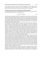
the emotional experience coefficient (see Figure 3) in function to the new parameters.
Fig. 3. Weighing of emotional experiences linked to new parameters – step 3
iGrace – Emotional Computational Model for EmI Companion Robot.
67
5.2.4 Sub-module ”Behaviour”
This module lets the behavioural expression that the robot will have in response to the
child’s discourse be chosen. From list L
4
, we have to extract emotional experiences with the
best coefficient into a new list L
5
. To avoid repetition, the first thing to be done was to filter
the emotional experiences that had already been used for the same discourse. A historical
base of behaviours associated to the discourse would help in this process. The second
process is to choose N emotional experiences from the list with the best coefficients. In the
case of the same coefficients, a random choice will be made. We currently have set the
number of emotional experiences to be extracted to three.
Another difficulty with this module is in the dynamics of behaviour and the choice of
expressions. It is important not to lose the interaction with the child by constantly repeating
the same expression for a type of behaviour. The choice of a large panel of expressions will
help us obtain different and unexpected interaction for the same sentence or same emotional
state.
5.3 ”Output” module
This module must be capable of expressing itself in function to the material characteristics it
is made of: microphone/HP, motors. The behaviour comes from the emotional interaction
module and will be divided into 3 main sections:
• Tone ”of voice”: characterized by a greater or lesser degree of audible signal and choice
of sound that will be produced by the robot. Within the framework of my research, the
interaction will remain non-verbal, thus the robot companion should be capable of
emitting sounds on the same tone as the seal robot ” Paro ”. These short sounds based
on the works of Kayla Cornale (Cornale, visited in 2007) with ” Sounds into Syllables ”,
are piano notes associated to primary emotions.
• Posture: characterized by the speed and type of movement carried out by each member
of the robot’s body, in relation to the generated behaviour.
• Facial expression: represents the facial expressions that will be displayed on the robot’s
face. At the beginning or our interaction study, we mainly work with ”emotional
experiences”. These should be translated into primary emotions afterwards, and then
into facial expressions. Note that emotional experience is made up of several primary
emotions.
6. Operating scenario
For this scenario, the simulator and the robot will be used for expressing emotions. This
system will allow us to compare the expression of the two media. The scenario takes place in
3 phases:
• System Initialization
• Simulation Event
• Processing event
• Reaction
6.1 System initialisation
At system startup, Moderator an Outputs module initialize variables like mood, personality
and emotion running the robot with values inFigure 4
Advances in Human-Robot Interaction
68
6.2 Simulation event
For this phase, a sentence is pronounced into the microphone allowing the system start
process. The selected phrase, extract from experiments with the robot and children in
schools is: ”Bouba’s mother is die”. From this sentence, the team of treatment and
understanding of discourse selects the following words: Mum, Be, Death. From this
selection, the 9 parameters of the module Inputs will be initialized as in Figure 5.
6.3 Processing event
The emotional interaction module processes the event received and generates a reaction to
the speech in six steps. Each of these steps allows us to obtain a list of emotional experiences
associated with a coefficient having a value between 0 and 100.
Step 1: Personality profile
This step, performed by the sub-module Moderator, produces an initial list of responses for
the robot based on its personality. The list on which treatment is based is the personality
profile of the robot (see Figure 4). Applying the equation 1 at this list, we get the first list of
emotional experiences L
1
(see Figure 4).
Fig. 4. List L
1
from Moderator
Step 2: Reaction to speech
This step, performed by the sub-module selector of emotional experiences, produces a list of
reactions to the speech of the interlocutor. An amotional and an affect vector is associated
with each concept and action of discourse, but only the emotional vector is taken into
account in this step. Using the equation 2, we add the vectors coefficient for each primary
common emotion. Only values greater or equal to 0 are taken into account in our
calculation. In the case of joy (see Figure 5), we have: V · joie = V1 · joie + V2 · joie = 1 + 0.
This vector fusion allows us to get list L
2
of emotional experiences to which we apply the
equation 3 to calculate the corresponding coefficients.
Step 3: Responding to the emotional state
This step, performed by the sub-module generator of emotional experiences, produces a list
L
3
of emotional experiences for the emotional state of the speaker when the speech is done.
The emotional state of the child being represented as a vector, we can obtain a list of
emotional experiences to which we apply the equation 4 for coefficient.
iGrace – Emotional Computational Model for EmI Companion Robot.
69
Fig. 5. List L
2
from Selector
Fig. 6. List L
3
from emotional state
Step 4: Fusion of lists
This step, performed by the sub-module generator of emotional experiences, allows the
fusion of all lists L
1
, L
2
, L
3
into L
4
and computing the new coefficient of emotional
experiences by using algorith see in Figure3. The new list L
4
is see in Figure 7.
Step 5: Selection of the highest coefficients
This step, performed by the sub-module behavior, achieves the 3 best emotional experiences
of the list L
4
into L
5
. The list will be first reduced by deleting emotional experiences that have
already been chosen for the same speech. In the case of identical coefficients, a random
selection will de made.
Advances in Human-Robot Interaction
70
Fig. 7. From Generator to Output module – List L
4
and L
5
Step 6: Initialization parameters of expression
The last step, performed by the sub-module behavior, calculates the parameters for the
expression of the reaction of the robot. We obtain the time expression in second of each
emotional experience (see Figure 7).
6.4 Reaction
This last phase, carried out by the output module, simulates the robot’s reaction to the
speech. With the list L
5
(see Figure 7) of reaction given by the emotional interaction module.
For each of the emotional experiences of the list associated with one or more emotions, we
randomly choose a facial expression in the basic pattern. This will be expressed using the
motor in the case of the robot or the GUI in the case of the simulator.
7. Experiments
The goal of the first experiment was to partially evaluate and validate the emotional model.
For this, we start we start experiment with a small public of all ages to gather the maximum
amount of information on the improvements needed for interaction. After analysis of the
results, the first improvements were made. For this experiment, only the simulation
interface was used.
7.0.1 Protocol
For the first step, having been carried out among a large public, it was not difficult to find
volunteers. However, we limited the number to 10 people because as we have already
stated, this is not the targeted public. We did not want to modify the interaction in function
to remarks made by adults. The first thing that was asked was to use abstraction as the
interface represented the face and behaviour of the robot, and that the rest (type of input,
ergonomy, etc.) was not to be evaluated. Furthermore, these people were asked to put
themselves in the place of a targeted interlocutor so as to make the most useful remarks.
To carry out the tests, we first chose a list of 4 phrases upon which the testers were to base
themselves. For each one, we included the following language information:
• Time of action: present.
• Language act: affirmative.
• Discourse context: real life.
This system helped us gain precious time that each person would use to make their
decisions. The phrases given were the following:
• Mum, Hug, Dad.
iGrace – Emotional Computational Model for EmI Companion Robot.
71
• Tiger, Attack, Grandma.
• Baby, Cry.
• I, Tickle, Sister.
7.1 Evaluation grid
After the distribution and explication of the evaluation grids, each person first had to go
through the following steps:
1. Give an affect (positive, negative, or neutral) to each word of the phrase.
2. Define their emotional state for the discourse.
3. Predict the emotional state of the robot.
Although this step was easy to do, it was rather long to input because some people had
trouble expressing their feelings. After inputting the information we could start the
simulation for each phrase. We asked the users to be attentive to the robot’s expression
because it could not be seen again. After observation of the robot’s behaviour, the users had
to complete the following information:
1. Which feelings could be recognized in the behaviour, and what was their intensity on
the scale: not at all, a little, a lot, do not know.
2. The average speed of the expression and length of the behaviour on a scale: too slow,
slow, normal, fast, too fast.
3. Did you have the impression there was a combination of emotions? Yes or no?
4. Was the sequence of emotions natural? Yes or no?
5. Are you satisfied with the robot’s behaviour? Not at all, a little, very much?
7.2 Results
The objective of this experiment was to evaluate the recognition of emotions through the
simulator, and especially to determine if the response the robot will give to the speech was
satisfying or not. As regards the rate of appreciation of the behaviour for each speech, 54%
for at lot of satisfaction and 46% for a little, we observed that all the users found the
simulator’s response coherent, and thereafter admitted that they would be fully satisfied if
the robot was as they were expected. The fact that testers answered about the expected
emotions had an influence on overall satisfaction.
For the rate of emotions recognition, 82% in average, the figures were very satisfactory and
allowed us to prepare the next evaluation on the classification of facial expressions for each
primary emotion. Not all emotions are on the graph because they bore no relation to the
sentences chosen. We have also been able to see that even if the results were still rather high,
there were some emotions which were recognized although they were not expressed. This
confirms the need to classify, and especially the fact that each expression can be a
combination of emotions. The next question is to know if the satisfaction rate will be the
same with the robot after the integration of the emotional model. The other results were
useful for the integration of the model on the robot:
• Speed of expressions: normal with 63%
• Behaviour length: normal with 63%
• Emotional combination: yes with 67%
• Natural sequences: yes with 71%
Advances in Human-Robot Interaction
72
8. EmI - robotic conception
EmI is currently in the integration and test phase for future experiments. This robot was
partially conceived by the CRIIF for the elaboration of the skeleton and the first version of
the covering (see Figure 8(c)). The second version (see Figure 8(d)), was made in our
laboratory. We will briefly present the robotic aspect of the elaborated work while waiting
for the second generation of it.
Fig. 8. EmI conception
The skeleton of the head (see Figure 8(a)) is completely made of ABS and contains:
• 1 camera at nose level to follow the face and potentially for facial recognition. The
camera used is a CMUCam 3.
• 6 motors creating the facial expression with 6 degrees of freedom. Two for the
eyebrows, and four for the mouth. The motors used are AX-12+. This allows us to
communicate digitally, and soon with wireless thanks to Zigbee, between the robot and
a distant PC. Communication with the PC is done through a USB2Dynamixel adapter
using a FTDI library.
The skeleton (see Figure 8(b)) of the torso is made of aluminium and allows the robot to turn
its head from left to right, as well as up and down. It also permits the same movements at
the waist. There are a total of 4 motors that create these movements.
iGrace – Emotional Computational Model for EmI Companion Robot.
73
Currently, communication with the robot is done through a distant PC directly hooked up
to the motors. In the short term, the PC will be placed on EmI to process while allowing for
interaction. The PC used will be a Fit PC Slim, at 500 Mhz, with 512 Mo of RAM and a 60 Go
hard drive. The exploitation system used is Windows XP. It is possible to hook up a mouse,
keyboard, and screen for modifications and to make the system evolve at any moment.
9. Conclusion and perspectives
The emotional model iGrace we propose allows to react emotionally to a speech given. The
first experiment conducted on a small scale has enabled us to answer some questions such
as length and speed of the robot expression, methods of information processing, consistency
of response and emotion recognition on a simulator. To fully validate the model, a new
large-scale experimentation will be repeated.
The 6 degrees of freedom used for the simulation give recognition rate very satisfactory. It is
our responsibility now to make a similar experiment on the robot to evaluate its
expressiveness. In addition, we undertook extensive research on the dynamics of emotions
in order to increase the fluidity of movement and make the interaction more natural. The
second experiment, with the robot, will allow to compare the recognition rate between the
robot and the simulator.
The next version of EmI will integrated a new texture, camera recognition and prosody
traitment. These parameters will allows us have a best recognition for emotional state of the
child. Some parts of modules and su-modules of the model have to be develop for a best
interaction.
10. Acknowledgements
EmotiRob is a project that is supported by ANR through the Psirob programme. The MAPH
project is supported by regional funding from la rgion Martinique and la rgion Bretagne. We
would like to first of all thank the different organisations for their financial support as well
as their collaboration.
The authors would also like to thank all of the people who have contributed to the
evaluation grids for the experiments, as well as the members of the Kerpape centre and IEA
”Le Bondon” centre for their cooperation.
Finally, the authors would also like to thank all of the participants in the experiments for
their time and constructive remarks.
11. References
Adam, C. & Evrard, F. (2005). Galaad: a conversational emotional agent, Rapport de recherché
IRIT/2005-24-R, IRIT, Universit Paul Sabatier, Toulouse.
Adam, C., Herzig, A. & Longin, D. (2007). PLEIAD, un agent motionnel pour valuer la
typologie OCC, Revue d’Intelligence Artificielle, Modles multi-agents pour des
environnements complexes 21(5-6): 781–811.
URL: Adam et al RIA.pdf
AIST (2004). Seal-type robot ”paro” to be marketed with best healing effect in the world.
URL: e/latest research/2004/20041208 2/20041208 2.html
Arnold, M. (1960). Emotion and personality, Columbia University Press New York.
Advances in Human-Robot Interaction
74
Bassano, D., Labrell, F., Champaud, C., Lemétayer, F. & Bonnet, P. (2005). Le dlpf: un nouvel
outil pour l’évaluation du développement du langage de production en français,
Enfance 57(2): 171–208.
Bloch, H., Chemama, R., Gallo, A., Leconte, P., Le Ny, J., Postel, J., Moscovici, S., Reuchlin,
M. & Vurpillot, E. (1994). Grand dictionnaire de la psychologie, Larousse.
Boyle, E. A., Anderson, A. H. & Newlands, A. (1994). The effects of visibility on dialogue
and performance in a cooperative problem solving task, Language and Speech 37(1):
1–20.
Breazeal, C. (2003). Emotion and sociable humanoid robots, Int. J. Hum Comput. Stud. 59(1-
2): 119–155.
Breazeal, C. & Scassellati, B. (2000). Infant-like social interactions between a robot and a
human caretaker, Adaptative Behavior 8(1): 49–74.
Brisben, A., Safos, C., Lockerd, A., Vice, J. & Lathan, C. (2005). The cosmobot system:
Evaluating its usability in therapy sessions with children diagnosed with cerebral
palsy.
Bui, T. D., Heylen, D., Poel, M. & Nijholt, A. (2002). Parlee: An adaptive plan based event
appraisal model of emotions, in S. B. Heidelberg (ed.), KI 2002: Advances in Artificial
Intelligence, Vol. 2479 of Lecture Notes in Computer Science, Springer Berlin /
Heidelberg, pp. 129–143.
Cambreleng, B. (2009). Nao, un robot compagnon pour apprendre ou s’amuser.
URL: />KX6itOmsA
Castel, Y. (visité en 2009). Psychobiologie humaine.
URL:
Cauvin, P. & Cailloux, G. (2005). Les types de personnalité: les comprendre et les appliquer avec le
MBTI (Indicateur typologique de Myers-Briggs), 6 edn, ESF éditeur.
Cornale, K. (visited in 2007). Sounds into syllables.
URL: www.soundsintosyllables.com
Dang, T H H., Letellier-Zarshenas, S. & Duhaut, D. (2008). Grace generic robotic
architecture to create emotions, Advances in Mobile Robotics: Proceedings of the
Eleventh International Conference on Climbing and Walking Robots and the Support
Technologies for Mobile Machines pp. 174–181.
de Rosis, F., Pelachaud, C., Poggi, I., Carofiglio, V. & Carolis, B. D. (2003). From greta’s mind
to her face: modelling the dynamics of affective states in a conversational embodied
agent, International Journal of Human-Computer Studies 59(1-2): 81–118. Applications
of Affective Computing in Human-Computer Interaction.
de Sousa, R. (2008). Emotion, in E. N. Zalta (ed.), The Stanford Encyclopedia of Philosophy, fall
2008 edn.
El-Nasr, M. S., Yen, J. & Ioerger, T. R. (2000). Flame—fuzzy logic adaptive model of
emotions, Autonomous Agents and Multi-Agent Systems 3(3): 219–257.
Gazdar, G. (1993). The simulation of Human intelligence, Donald Broadbent edition.
Gratch, J. & Marsella, S. (2005). Evaluating a computational model of emotion, Autonomous
Agents and Multi-Agent Systems 11(1): 23–43.
Greenspan, P. (1988). Emotions & reasons: an inquiry into emotional justification, Routledge.
James,W. (1884). What is an emotion?,
Mind 9: 188–205.
iGrace – Emotional Computational Model for EmI Companion Robot.
75
Jost, C. (2009). Expression et dynamique des émotions. application sur un avatar virtuel, Rapport
de stage de master recherche, Université de Bretagne Sud, Vannes.
Jung, C. G. (1950). Types psychologiques, Georg.
Lange, C. G. & (Trans), I. A. H. (1922). The emotions, Williams & Wilkins Co, Baltimore, MD,
US.
Larivey, M. (2002). La puissance des émotions: Comment distinguer les vraies des fausses., de
l’homme edn, Les éditions de l’Homme, Québec.
Lathan, C., Brisben, A. & Safos, C. (2005). Cosmobot levels the playing field for disabled
children, interactions 12(2): 14–16.
Lazarus, R. & Folkman, S. (1984). Stress, Appraisal, and Coping, Springer Publishing
Company.
URL: />20&path=ASIN/0826141919
Lazarus, R. S. (1991). Emotion and Adaptation, Oxford University Press, New York.
Lazarus, R. S. (2001). Relational meaning and discrete emotions, Oxford University Press,
chapter Appraisal processes in emotion: Theory, methods, research., pp. 37–67.
Le-Pévédic, B., Shibata, T. & Duhaut, D. (2006). Etude sur paro. study of the psychological
interaction between a robot and disabled children.
Libin, A. & Libin, E. (2004). Person-robot interactions from the robopsychologists’ point of
view: the robotic psychology and robotherapy approach, Proceedings of the IEEE
92(11): 1789–1803.
Myers, I. B. (1987). Introduction to type: A description of the theory and applications of the Myers-
Briggs Type Indicator, Consulting Psychologists Press Palo Alto, Calif.
Myers, I. B., McCaulley, M. H., Quenk, N. L. & Hammer, A. L. (1998). MBTI manual, 3 edn,
Consulting Psychologists Press.
Ochs, M., Niewiadomski, R., Pelachaud, C. & Sadek, D. (2006). Expressions intelligentes des
émotions, Revue d’Intelligence Artificielle 20(4-5): 607–620.
Ortony, A., Clore, G. L. & Collins, A. (1988). The Cognitive Structure of Emotions, Cambridge
University Press.
URL:
20&path=ASIN/0521353645
Ortony, A. & Turner, T. (1990). What’s basic about basic emotions, Psychological review 97(3):
315–331.
Parrott, W. (1988). The role of cognition in emotional experience, Recent Trends in Theoretical
Psychology, w. j. baker, l. p. mos, h. v. rappard and h. j. stam edn, New-York, pp.
327– 337.
Parrott,W. G. (1991). The emotional experiences of envy and jealousy, The psychology of
jealousy and envy, p. salovey edn, chapter 1, pp. 3–30.
Parrott, W. G. (2000). Emotions in Social Psychology, Key Readings in Social Psychology,
Psychology Press.
Peters, L. (2006). Nabaztag Wireless Communicator,
Personal Computer World 2.
Petit, M., Pévédic, B. L. & Duhaut, D. (2005). Génération d’émotion pour le robot maph:
média actif pour le handicap, IHM: Proceedings of the 17th international conference on
Francophone sur l’Interaction Homme-Machine, Vol. 264 of ACM International
Conference Proceeding Series, ACM, Toulouse, France, pp. 271–274.
Advances in Human-Robot Interaction
76
Pransky, J. (2001). AIBO-the No. 1 selling service robot, Industrial robot: An international
journal 28(1): 24–26.
Rousseau, D. (1996). Personality in computer characters, In Artificial Intelligence, AAAI Press,
Portland, Oregon, pp. 38–43.
Saint-Aimé, S., Le-Pévédic, B. & Duhaut, D. (2007). Building emotions with 6 degrees of
freedom, Systems, Man and Cybernetics, 2007. ISIC. IEEE International Conference on,
pp. 942–947.
Sartre, J P. (1995). Esquisse d’une théorie des émotions (1938), Herman et Cie, Paris.
Scherer, K. R. (2005). What are emotions? and how can they be measured?, Social Science
Information 44(4): 695–729.
Shibata, T. (2004). An overview of human interactive robots for psychological enrichment,
IEEE 92(11): 1749–1758.
Solomon, R. C. (1973). Emotions and choice, The Review of Metaphysics pp. 20–41.
van Breemen, A., Yan, X. & Meerbeek, B. (2005). icat: an animated user-interface robot with
personality, AAMAS ’05: Proceedings of the fourth international joint conference on
Autonomous agents and multiagent systems, ACM, New York, NY, USA, pp. 143–144.
Wilksa, Y. & Catizone, R. (2000). Encyclopedia of Microcomputers.
5
Human System Interaction through
Distributed Devices in Intelligent Space
Takeshi Sasaki
1
, Yoshihisa Toshima
2
,
Mihoko Niitsuma
3
and Hideki Hashimoto
1
1
Institute of Industrial Science, The University of Tokyo,
2
Daikin Industries, Ltd.,
3
Chuo University
Japan
1. Introduction
Intelligent Space (iSpace) is a space with ubiquitous sensors and actuators (Lee &
Hashimoto, 2002). iSpace observes the space using the distributed sensors, extracts useful
information from the obtained data and provides various services to the users through the
actuators. iSpace can be considered as an “invisible” robot that is united with the
environment since it can carry out the fundamental functions of robots - observation,
recognition and actuation functions.
This type of spaces is also referred to as smart environment, smart space, intelligent
environment, etc. and recently there is a growing number of research work (Cook & Das,
2004). Some smart environments are designed for supporting the users in informative ways.
For example, a meeting support system (Johanson et al., 2002) and a healthcare system
(Nishida et al., 2000) using distributed sensors were developed. Other smart environments
are used for support of mobile robots to provide physical services. Delivery robots with
ubiquitous sensory intelligence were developed in an office room (Mizoguchi et al., 1999)
and a hospital (Sgorbissa & Zaccaria, 2004). The functions of mobile robot navigation
including path planning (Kurabayashi et al., 2002) and localization (Han et al., 2007),
(Hwang & Shih, 2009) of mobile robots were assisted by using information from distributed
devices. Fig. 1 shows the configuration of our iSpace which is able to support human in both
informative and physical ways.
iSpace has to recognize requests from users to provide the desired services and it is
desirable that the user can request the services through natural interfaces. Therefore, a
suitable human-iSpace interface is needed. Gesture recognition has been studied extensively
(Mitra & Acharya, 2007) and human motions are often utilized as an interface in smart
environments. A wearable interface device, named Gesture Pendant, was developed to
control home information appliances (Mynatt et al, 2004). This device can recognize hand
gestures using infrared illumination and a CCD camera. Gesture pads are also used as input
devices (Youngblood et al, 2005). Speech recognition is considered as another promising
approach for realizing an intuitive human-iSpace interface. The smart environment research
Advances in Human-Robot Interaction
78
project described in (Scanlon, 2004) utilizes distributed microphones to recognize spoken
commands.
On the other hand, interaction can also be started by the space. If iSpace finds that a user is
in trouble based on observation, for example, a mobile robot in the space would go to help
the user. To realize this, human activity and behaviour recognition methods in smart
environments are studied actively (Mori et al, 2007), (Oliver et al, 2004). It is also important
to develop actuators including display systems, audio systems and mobile robots in order to
provide services based on the observed situations.
Here both types of human-iSpace interaction mentioned above are described in the following
sections. Section 2 and 3 introduce our human-iSpace interfaces - a spatial memory and a
whistle interface. The spatial memory uses three-dimensional positions whereas the whistle
interface utilizes frequency of sounds to activate services. Section 4 presents an information
display system using a pan-tilt projector. Sections 2, 3 and 4 give also experimental results to
demonstrate the developed system. Finally, a conclusion is given in section 5.
iSpace
Environment
information
decision
services
iSpace
Environment
information
decision
services
Fig. 1. Configuration of Intelligent Space
2. Spatial memory
Fig. 2 shows a schematic concept of the spatial memory. The spatial memory regards
computerized information, such as digital files and commands, as externalized knowledge
and enables human to store computerized information into the real world by assigning a 3-
D position as the memory address. By storing computerized information into the real world,
users can manipulate the information, as if they manipulated physical objects. For example,
as shown in Fig. 2, conference proceedings can be organized in front of file cabinets or
special memories might be stored into the second drawer from the top.
Human System Interaction through Distributed Devices in Intelligent Space
79
Proceeding 2000
Proceeding 2004
demo movies
Robot program
Commands for robot
Documents
of robot
Proceeding 2000
Proceeding 2004
demo movies
Robot program
Commands for robot
Documents
of robot
Fig. 2. Concept of the spatial memory
2.1 Definitions of terms
1) SKT (Spatial-Knowledge-Tag): We introduce a virtual tag, which associates computerized
information with a spatial location. We will call them SKTs. SKT has three important
parameters, namely: 1) stored computerized information; 2) 3-D position as a memory
address; and 3) size of an accessible region. The details of an accessible region will be
explained later. Stored computerized information is called spatial memory data.
Environmental information, such as arrangements of equipment and objects, is adopted as
tags, which represent the whereabouts of externalized knowledge. Equipment placed in a
working environment has visually distinguishable functions, respectively, and humans are
able to recognize them easily by using their own cognitive abilities. Therefore, when real
objects represent tags, they will play a role of a trigger to recall stored data and will be
effective to memorize the whereabouts. In addition, the location of objects can be utilized to
arrange externalized knowledge for easy recall.
There have been several approaches to associate computerized information with real objects,
e.g., using Radio Frequency Identification (Kawamura et al., 2007), (Kim et al., 2005) or
using 2-D barcode (Rekimoto et al. 1998). The approaches are useful to recognize the objects
in a physical sense. However, there is a need to directly attach a hardware tag to each object
in advance, and the user can only arrange computerized information for predetermined
objects. Optional properties regarding accessibility, security, and mobility are not easily
changed because they depend on hardware specifications, such as antennas or cameras.
There are two key differences between 3-D position-based method and hardware-tag-based
method, such as 2-D barcodes. First, in the case of using 3-D position, we do not need to
directly attach the hardware tag to each object, and therefore we can store information
freely, if the position and the motion of human can be measured. Second, stored data
manipulations, such as changing optional properties, are easier than using the hardware tag.
Another important aspect of our spatial memory is that the SKT can also take a human-centric
approach to store the computerized information. More specifically, let us just consider the case
where the coordinate frame is defined based on the human body. We can realize
Advances in Human-Robot Interaction
80
transformation from a human-centric coordinate frame to the real world, since the human can
also take an option to carry the SKTs with his motion so that the relative position of SKTs will
not be changed, for example, “my left side 2 m away to get access to file A,” “my right side 10
m away to call my friend B.” However, of course, if the user attaches the computerized
information to a real object in the initial stage, the approach on the spatial memory needs to
recognize an object with a human intuitive assist to register the object to the memory.
2) Human Indicator: The spatial memory whose address is represented by its 3-D position
requires a new memory access method. In order to achieve intuitive and instantaneous
access method that anyone can apply, the spatial memory adopts an indication of a human
body as a memory indicator. Therefore, when using the spatial memory, a user can retrieve
and store data by directly indicating the positions using his own body, for example, user’s
hand or user’s body. The position based on the user’s body used for operating the spatial
memory is called a “human indicator.”
However, it is impossible for a human to indicate the exact position of the spatial memory
address every time. To easily and robustly access an SKT by using the human indicator, it is
necessary to define an accessible region for each SKT. The accessible region is also needed for
the arrangement of several SKTs by distinguishing their locations from others. The size of
accessible region is determined based on the accuracy of the human indicator and its action
type. For example, when using a hand for the human indicator, the user can indicate more
accurately than using the body position. Therefore, a small size of accessible region can be
achieved when using a hand, whereas a large one will be needed for a body human indicator.
We notice here that a guideline to determine the size of a human indicator using a hand has
been obtained. In our previous work, we have investigated the accuracy of the human
indicator (Niitsuma et al., 2004) using the user’s hand. The accuracy is defined by the
indication error, which is the distance between a spatial memory address of SKT and the
human indicator. Investigations of two cases of human activities were carried out, namely:
1) the case of performing only the indication task and 2) the case of performing the
indication task during another task. The results show the different margin of indication
error between two cases. The accuracy of case 2 is worse than case 1 because the error
margin of case 2 is larger than case 1. In order to achieve both smooth access and
arrangement of several SKTs, accessible region is defined as follows. The accessible region is
the sphere whose origin is located at a spatial memory address of SKT, whereas the radius is
determined according to human activities: the radius in the case of just the indication task
was found to be about 20 cm, and the radius in the case of indicating while performing
another task was found to be about 40 cm.
3) Spatial Memory Address: As explained above, spatial memory addresses define spatial
locations of computerized information in the spatial memory. Addressing method of the
spatial memory system adopts a human-indicator-centered method, i.e., a position indicated
by a human indicator is used for a spatial memory address. Consequently, the action for
storing data into spatial memory can be carried out intuitively by pointing a spatial location
as well as the action for accessing SKT. The implemented spatial memory has a 3-D
coordinate system whose origin is at an arbitrary point in a space.
2.2 Usability evaluation of the spatial memory
Memorizing both the contents of SKTs and their whereabouts are required to utilize the
spatial memory. If the users learn SKT positions and contents, they can get access to aimed
Human System Interaction through Distributed Devices in Intelligent Space
81
SKTs quickly without errors. Namely, it can be assumed that access time will be limited only
by the physical access time necessary to utilize a human indicator and indicate the position
of an aimed SKT. Therefore, the accessibility of the spatial memory and the effectiveness of
memorizing were investigated from the viewpoint of the time needed to access SKTs.
Human subjects memorized some SKTs, which had been arranged in advance, then accessed
them. The task started from the situation where each subject did not have any information
about the whereabouts and ended when the subject could access all SKTs. We measured the
task completion time of each subject by changing intervals of tasks; more specifically 1 h
later, 3 h later, and up to 20 days later, in order to check how the subject would memorize
the spatial arrangement of SKTs. We then analyzed the time variation of the task completion
time. Here, the accessible region was determined as the sphere with radius of 20 cm. The
experiment was carried out by six subjects (21–26 years old, science or engineering
students). All subjects have used the spatial memory for about 30 min before the
experiment, and they know the usage.
The details of the specified task are described as follows.
1. Initialization phase
a) An experimenter stores seven SKTs whose spatial memory data are given by images.
2. Learning phase
a) A subject accesses stored SKTs and memorize the contents and the whereabouts. In
this step, the “access indicator” which shows colors based on the distance between the
human indicator and the spatial memory address of the nearest SKT on a computer
display is used.
b) Learning is ended by the subject’s decision.
3. Test phase
a) Experimenter specifies the content of the SKT.
b) The subject accesses the specified SKT.
c) Phases 3-a and 3-b are repeated until all SKTs were accessed by the subject.
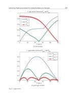
The task completion time from phase 2-a to phase 3-c was measured for each subject. Fig. 3
(a) shows the completion time of each subject (Subjects 1–6). The horizontal axis represents
logarithmic time [h] that had passed from the experiment start time, and the vertical axis
represents the completion time [s]. All subjects learned the contents and the whereabouts of
seven SKTs at the first performance, which resulted in a long completion time. The
completion time of the first performance of Subject 6 is the shortest because he stored all
SKTs before the experiment. All subjects completed accessing all SKTs at the performance
after about four weeks from the first performance as short as the second performance.
Although Subject 3 required learning at the third performance, the learning time was 50%
less than the first performance. After the third performance, he completed the tasks in a time
as short as the other subjects did.
These results show the easiness of accessing the stored SKTs by memorizing the spatial
locations because almost all subjects did not require learning of SKTs after the first
performance. The completion time at the last performance of all subjects became 18–24 s,
which shows that the accessibility was maintained or even improved over time.
Fig. 3 (b) shows the completion time of each subject depending on the intervals between the
performances in order to investigate the effectiveness of memorizing the stored SKTs. The
horizontal axis represents the logarithmic interval time [h] of task executions, and the
vertical axis represents the completion time [s] of each task performance. The figure shows the
completion times from the second to the last performance. In the experiment, the interval
Advances in Human-Robot Interaction
82
between performances was increased according to the number of performances, although the
interval time is not exactly the same among subjects. Thus, the last performances of all subjects
are performed with an interval time of about 500 h (about 20 days).
The completion times of three subjects fluctuated until the first half of the experiment,
where the interval time was less than 20 h. The variations of the subjects’ completion time,
however, decreases when the number of the execution times increase, and the completion
times become shorter. Other subjects carried out the task in an almost fixed time through all
performances. The time 18–24 of the last performances is close to the physically needed time
to access SKTs. In addition, all subjects successfully completed getting access to all SKTs in
the performance even after about 20 days from the first performance. As shown in Fig. 3 (b),
the performance after 20 days is as short as the performance of 2-h duration.
The results show that the subjects were able to recall the stored SKTs without forgetting
them, and accessibility of the spatial memory has been maintained or even improved even if
the interval time between usages increased. Therefore, the spatial memory approach in
which the access method uses the human body and the storing method tags a real
environment is effective for minimizing the forgetting of stored computerized information
even if time has passed since it was stored.
(a) (b)
Fig. 3. Result of the usability evaluation experiment (a) time variation of the task completion
time of each subject, (b) task completion time focused on the task interval
2.3 Service execution using spatial memory
By storing services into a space using the spatial memory, we can execute various services in
iSpace. Fig. 4 shows an example of a service execution using the spatial memory. In the
example, the spatial memory is used for sending commands to a mobile robot. A “call
robot” service was stored behind a user and the user called a mobile robot by indicating the
position (Fig. 4 (a)-(c)). We also developed an interface to create and delete SKTs. This
interface contains a speech recognition unit and SKTs can be managed using voice
commands. In the example, another “call robot” service was stored in the user-specified
position by using the interface (Fig. 4 (d)-(f)).
Human System Interaction through Distributed Devices in Intelligent Space
83
(a) (b)
(c) (d)
(e) (f)
Fig. 4. Service execution using the spatial memory (a)request for ”call robot” service by
indicating the specified position, (b)(c)execution of ”call robot” service, (d)service
management by using a voice command, (e)storing the “call robot” service, (f)execution of
”call robot” service
Advances in Human-Robot Interaction
84
3. Sound interfaces
Sound interfaces provide another method for activating services in iSpace. Although iSpace
has speech recognition units as shown in the previous section, we introduce a simple but
robust sound interface using a human whistling in this section.
Here we consider the frequency of sounds as a trigger to call a service, i.e. a service is
provided when the system detects a sound which has the corresponding frequency. The
advantages of using a whistle as an interface are that humans do not have to carry any
special devices and the range of the sound can be expanded through exercises to activate
different types of services depending on the pitch. In addition, it carries a long way and can
be easily detected by using distributed microphones. Fig. 5 shows an example of sound
waveforms and their frequency spectrum for various sound sources obtained by Fourier
analysis. As shown in Fig. 5 (d), the sound of a whistle is considered as a pure tone and
easily recognized by considering the percentage of the power of the main frequency
component among the total power of the sound.
(a) (b)
(c) (d)
Fig. 5. Result of frequency analysis for various sound sources (a)human voice, (b)melodica,
(c)metallophone, (d)human whistle
Fig. 6 shows an example of human-robot interaction through the sound interface. In this
example, each sound denotes different commands and a mobile robot is controlled based on
the commands. Here we tested various sound sources and played a sound of a different
pitch for each source. As shown in the figure, the system detected the sound and the mobile
robot generated the corresponding motion successfully. We note that as also shown in Fig. 6,
since the sound of the melodica contains rather large harmonic components, the system
sometimes failed to detect the sounds. On the other hand, a whistle is robustly recognized
even in the presence of environmental noise.
By associating the frequency of sounds with services, this interface can be used to activate
various services by the users.
Human System Interaction through Distributed Devices in Intelligent Space
85
(a) (b)
(c) (d)
Fig. 6. Sending commands to a mobile robot using various sound sources (a)recorder,
(b)melodica, (c)metallophone, (d)human whistle
4. Information display using a pan-tilt projector
Based on observation of users in the space, iSpace can actively provide information which is
expected to be useful for the users. Here we consider an interactive information display
system using visual information. The information display system uses a projector with a
pan-tilt unit, which is able to project an image toward any position according to human
movement in the space. By utilizing the interactive information, many applications can be
developed, for example, the display of signs or marks in public spaces, or various
information services in daily life.
However, main issues in active projection are distortion of the projection image and
occlusion of the image. These issues are addressed in the following subsections.
4.1 Compensation of projection image
When projection direction is not orthogonal to the projection surface, projection distortion
occurs. Moreover the size of the projected image depends on the distance to the projection
surface. Therefore with change of the projection point it is not possible to provide a uniform
Advances in Human-Robot Interaction
86
image to a user. The projector provides uniform projection toward any position by
compensation of the projection image by using a geometric model and inverse perspective
conversion.
The resize ratio γ for compensation of the image size is given as follows.
γ(d)=W/t(d) (1)
where d denotes distance between the projector and the projection surface, W is the desired
image size and t(d) is a image size on the projection surface.
Distortion is also caused by the angle between the optical axis of the projector and the
projection surface. The geometrical definition is shown in Fig. 7. As shown in this figure, the
pan-tilt projector projects an image toward O
p
. The plane Q is the projection surface and the
plane R is orthogonal to the projection direction. The points r
1
to r
4
denote the corners of the
non-distorted image whereas the points q
1
to q
4
are the corresponding points on the
distorted image. A relation between a point p
Q
on plane Q and a point p
R
on plane R is
obtained based on perspective conversion:
~
11
QR
pp
⎡
⎤⎡⎤
⎢
⎥⎢⎥
⎣
⎦⎣⎦
QR
H
(2)
This conversion matrix H
QR
is a 3×3 matrix and the degree of freedom is 8. Therefore, if four
or more sets of corresponding points of p
Q
and p
R
are given, we can identify H
QR
and
represent image distortion. The corresponding points can be found by the intersection of the
plane Q with the line through r
i
from the projection origin (lens). The inverse matrix of H
QR
represents compensation of image distortion and we can get pre-compensated output image.
Fig. 7. Geometrical definition of image distortion
4.2 Occlusion avoidance
Projection occlusion occurs when human enters into the area where the human obstructs the
projection. This problem sometimes happens in active projection due to human movement
or change in projection environment. Hence, by creating an occlusion area and a human
Human System Interaction through Distributed Devices in Intelligent Space
87
(obstruction) model and judging whether they overlap with each other, occlusion can be
detected and avoided.
We modelled the shape of projection light and human are corn and cylinder, respectively.
We judge the overlap between these two models to detect occlusion. Moreover, not only
humans but also other objects including chairs and tables could cause the occlusion
problem. Our occlusion avoidance algorithm can be used by considering the object shape
model.
The avoidance method needs to modify the projection position so that the user can easily
view the image. Fig. 8 shows the determination of the modified position. In the situation
that the projection position is on the left side of the human model, the projection direction is
moved to the left to avoid occlusion since it requires less angular variation compared to the
rightward movement. On the contrary, when the projection position is on the right side of
the human model, it moves to the right for the same reason. If the calculated correction
angle is greater than the limit correction angle
θ
max
, the projection position is moved away
from the human.
Fig. 8. Determination of the modified position for occlusion avoidance
4.3 Visitor guidance application
We developed a visitor guidance application as an example of interactive informative services.
Fig. 9 shows the procedure of the visitor guidance. When iSpace detects a visitor using
distributed sensors, the projector displays a guidance panel in front of the visitor. In this case,
two messages “call robot” and “view map” are shown (Fig. 9 (a)(b)). If the visitor stands on the
“call robot,” the projector provides a message “calling robot” and a mobile robot comes
toward a user (Fig. 9 (c)). On the other hand, if the visitor stands on “view map,” the projector
displays the map of the space in front of the visitor (Fig. 9 (d)). In addition, the projector
indicates the direction of the place that is selected by the visitor (Fig. 9 (e)(f)).
Advances in Human-Robot Interaction
88
(a) (b)
(c) (d)
(e) (f)
Fig. 9. Guidance application using a pan-tilt projector (a)detection of a visitor, (b)display of a
guidance panel (c)“call robot” service, (d)“view map” service, (e) selection of a place where
the visitor wants to go (in the “view map” service), (f)indication of the direction of the place
selected by the visitor (in the “view map” service)
5. Conclusion
Intelligent Space (iSpace) is an environmental system, which has multiple distributed and
networked sensors and actuators. Since a variety of sensors including cameras,