Advances in Human Robot Interaction Part 9 ppsx
Bạn đang xem bản rút gọn của tài liệu. Xem và tải ngay bản đầy đủ của tài liệu tại đây (4.51 MB, 25 trang )
A Quantitative Evaluation Method of Handedness Using Haptic Virtual Reality Technology
189
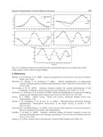
Fig. 11. Handedness
The tendency of force test was a little different from the other two tests. The reason for this
difference should be studied in the future.
This chapter has been written based on paper ”A Quantitative Evaluation Method of
Handedness Using Haptic Virtual Reality Technology” that was presented at the 16th IEEE
International Symposium on Robot & Human Interactive Communication, (IEEE RO-MAN
2007, Jeju, Korea, August, 2007).
6. References
Bagesteiro, L.B. & Sainburg, R.L. (2002). Handedness: Dominant Arm Advantages in
Control of Limb Dynamics, Journal of Neurophysiology, Vol.88, No.5, pp.2408-2421
Burdea, G.C. (1996). Force and Touch Feedback for Virtual Reality, A Wiley-Interscience
Publication, JohnWiley & Sons, Inc.
Fujiwara, N., Kushida, N., Murakami, T. & Fujimoto, S. (2003). Upper Limb Coordination
Differs Among Ages and Between Dominant and Non-dominant Hands Utilizing
Digital Trace Test, Journal of health sciences, Hiroshima University, Vol.2, No.2, pp.22-
28 (in Japanese)
Matsuda, I., Yamaguchi, M. & Yoshida, K. (1986). Quantitative Discrimination of
Handedness – Preliminary Study Using Discriminant Analysis Approach –,
Sagyouryouhou (Journal published by Japanese Association of Occupational Therapists),
Vol.5, pp.40-41 (in Japanese)
Oldfield, R.C. (1971). The Assessment and Analysis of Handedness: The Edinburgh
Inventory, Neuropsychologia, Vol.9, No.1, pp.97-113
Wu, J., Morimoto, K. & Kurokawa, T. (1996). A Comparison between Effect of Handedness
and Non-handedness on Touch Screen Operation, Transactions of Human Interface
Society, Vol.11, No.4, pp.441-446 (in Japanese)
Advances in Human-Robot Interaction
190
Yoshikawa, T., Yokokohji, Y., Matsumoto, T. & Zheng, X-Z. (1995). Display of Feel for the
Manipulation of Dynamic Virtual Objects, Journal of Dynamic Systems, Measurement,
and Control, Vol.117, No.4, pp.554-558
Yoshikawa, T. & Yoshimoto, K. (2000). Haptic Simulation of Assembly Operation in Virtual
Environment, Proceedings of the ASME, Dynamic Systems and Control Division–2000,
pp.1191-1198
12
Toward Human Like Walking
– Walking Mechanism of 3D Passive
Dynamic Motion with Lateral Rolling
– Advances in Human-Robot Interaction
Tomoo Takeguchi, Minako Ohashi and Jaeho Kim
Osaka Sangyo University
Japan
1. Introduction
It may not be so science fiction any more that robots and human live in the same space. The
robots may need to move like human and to have shape of humanoid in order to share the
living space. Some robots may be required to walk along with human for special care. This
requires robot to be able to walk like human and to sense how humans walk. Human walks
by maximizing walking in between passive walking and active walking in effective manner
such as less energy, less time, and so on (Ishiguro & Owaki, 2005). It is important to clarify
the mechanisms of passive walking. This study is the first step to decrease the gap between
robots and human in motion, advance in human-robot interaction.
Most robots use actuators at each joint, and follow a certain selected trajectory in order to
walk as mentioned active walking before. So, considerable power source is necessary to
drive and control many actuators in joints.
On the other hand, human swings a leg, leans its body forward, and uses potential energy in
order to walk as if human tries to save energy to walk. Walking down the slope is one of the
easiest conditions to walk (Osuka, 2002). The application of these human walking to the
robots is called passive dynamic walking. A possibility to reproduce passive dynamic
walking experimentally is introduced by McGeer (McGeer, 1990). Giving a simply
structured walker proper initial conditions, the walker walks down the slope by inertial and
gravitational force without any artificial energy externally.
Goswami et al. carry out extensive simulation analysis, and show stability of walking and
several other phenomena (Goswami et al., 1998; Goswami et al., 1998). In addition, Osuka
et al. reproduce passive dynamic walking and the phenomena experimentally by using
Quartet (walker)(Osuka et al., 1999; Osuka et al., 2000).
However, the both studies constrain the yaw and rolling motion in order to simplify the
analyses. Also, these analyses are made for legs without knees, so that extra care was
necessary to make experimental analyses harder because the swing legs hit the slope at the
position that it passes the supporting leg.
In this study, the analyses were made three-dimensional walking with rolling motion. The
3D modeling, and simulation analysis were performed in order to search better walking
Advances in Human-Robot Interaction
192
condition and structural parameters. Then, the 3D passive dynamic walker was fabricated in
order to analyze the passive dynamic walking experimentally.
2. Modelingof 3D passive walker
A compass gait biped model for walking is a model which constrains the motion into a two
dimensional plane. The walker for this model has to have four or eight legs to cut off the
rolling motion for experimental analyses. In addition, there is foot-scuffing problem at the
time when a swing leg is passing the side of support leg.
So, 3D passive walker model is used to solve the problems stated above, and to investigate
the stableness of the walker. The modeling and simulation of this study was inspired by
Tedrake et al. (Tedrake, 2004; Tedrake et al., 2004).
2.1 3D Model of passive walker
The 3D model of passive walker is shown in Fig. 1. Each parameters used in this model is
shown in Table1 and 2.
Fig. 1. 3D Model of Passive Walker
Symbol Lateral Plane Quantity
M Mass 2.5 kg
I Inertia 533 kgcm
2
R
L
Radius of foot curve 50 cm
A Distance between CL and center of gravity 29 cm
U Angle of rolling
V Angle between center line and line v 0.038 rad
Table 1. Parameters for Model in Lateral Plane
Toward Human Like Walking – Walking Mechanism of 3D Passive
Dynamic Motion with Lateral Rolling– Advances in Human-Robot Interaction
193
Symbol Sagittal Plane Quantity
m
l
Mass of a leg 1.25 kg
l
I
Inertia of a leg 47.4 kgcm
2
R
s
Radius of foot curve 38 cm
B Distance CS and center of leg 17 cm
D Distance between the center of curvature and hip 4.7 cm
k
s
Angle of swing leg
k
ns
Angle of support leg
S Angle of slope 0.035 rad
Table 2. Parameters for model in sagittal plane
This model is a 3-D passive walker with two legs connected at hip with simple link
structure. Legs do not have knees. Foot with concaved surface allows the rolling motion, so
that walking is expanded 3D space. Especially, the rolling motion in lateral plane solves the
scuffing problem at the moment when swing leg is passing through supporting leg. In
sagittal plane, support leg can be seen as an inverted pendulum, and swing can be seen as
simple pendulum for the motion of bipedaling walker.
The assumption that the yaw motion was small enough to ignore was made for simplifying
the numerical analysis, and analysis was carried in a way the space is dividing into lateral
and sagittal plane.
2.2 Equation of motion for lateral plane
The equation of motion for lateral plane is given. It is assumed that the foot of support leg is
on contact and not slipping with surface of slope until becoming swing leg.
0)u(Gu)u,u(Cu)u(H =++
(1)
H(u) is a matrix for inertial force, )u,u(C
is a matrix for centrifugal force, and G(u) is a
vector for gravitational force in (1). For this equation, the component would change
according to the angle of rolling, u.
When only supporting leg is on contact on slope (
u >v), the each component is shown in
(2).
ucosamR2mRmaI)u(H
L
2
L
2
−++=
usinuamR)u,u(C
L
=
usinmga)u(G = (2)
When changing the supporting leg (
u
≤
v), the each component is shown in (3).
)wucos(amR2mRmaI)u(H
L
2
L
2
−−++=
0)u,u(C =
)wsinRusina(mg)u(G
L
−
=
(3)
Advances in Human-Robot Interaction
194
Under condition of u>0, w is defined as w=u-v, and under condition of u<0, w is defined as
w=u+v in (3).
When the angle of rolling is zero (u=0), the swing leg collides with slope. This collision is
assumed to be inelastic collision. The equation of collision can be shown as (4).
]
avcosR
vsinR
tan2cos[uu
L
L
1
⎟
⎟
⎠
⎞
⎜
⎜
⎝
⎛
−
=
−−+
(4)
Superscripts - and + means before and after collision accordingly in (4).
2.3 Equation of motion for sagittal plane
The equation of motion for sagittal plane is shown as (5).
0)q(Gq)q,q(Cq)q(H
=
+
+
(5)
q is a vector for angle of support and swing leg, H(q) is a 2 by 2 matrix for inertial force,
)q,q(C
is a 2 by 2 matrix for centrifugal force in (5). G(q) is a vector for gravitational force in
(5). The components of (5) can be expressed in (6).
H(u) is a matrix for inertial force, )u,u(C
is a matrix for centrifugal force, and G(u) is a
vector for gravitational force in (1). For this equation, the component would change
according to the angle of rolling, u.
When only supporting leg is on contact on slope ( u >v), the each component is shown in (2).
)skcos()db(Rm2RmdmbmIH
ss
l
2
s
l
2
l
2
ll
11
−+−+++=
)}skcos(R)kkcos(d){db(mHH
nssnss
l
2112
−
−
−
−
=
=
2
ll
22
)db(mIH −+=
nsnss
l
sss
l
11
k)kksin()db(dm
2
1
k)sksin()db(RmC
−−+−+=
}k)sksin(R)k
2
1
k)(kksin(d){db(mC
nsnsssnsnss
l
12
−+−−−=
}k)sksin(R
2
1
)k
2
1
k)(kksin(d){db(mC
nsnsssnsnss
l
21
−−−−−=
snsss
l
12
k)}sksin(R)sksin(d){db(m
2
1
C
−+−−=
}ssinR2ksin)db{(gmG
ss
l
1
−
+
=
ns
l
2
ksin)db(gmG −
=
(6)
The equation for collision can be shown for before and after the collision by the conservation
law for angler momentum in (7)
Toward Human Like Walking – Walking Mechanism of 3D Passive
Dynamic Motion with Lateral Rolling– Advances in Human-Robot Interaction
195
−−++
= q)q(Zq)q(Z
(7)
Superscripts - and + means before and after collision accordingly in (7). )q(Z
+
and )q(Z
−
are matrices for the coefficients of collision. Components in (7) are shown as (8).
bdbR2)skcos(bR2)skcos(R)db()kkcos(bd2Z
22
snssnsssns11
−++−−−+−−=
−
)}skcos(Rb){db(ZZ
nss2112
−−−==
−−
0Z
22
=
−
)}db()skcos(R)kkcos(d){db(Z
ssnss11
−+−−−−=
+
)skcos(bRR2d)skcos()d2b(R)skcos()db(RZ
nss
2
s
2
nssss12
++++−+−−−−=
+
)kkcos()db(d)k2cos(b
nssns
2
−−+−
2
21
)db(Z −=
+
)}skcos(R)kkcos(d){db(Z
ssnss22
−−−−=
+
(8)
3. Simulation results
Structural parameters and numerical parameters are searched for stable walking motion.
Since there is no effective theory for the stability analysis, the only way is to try the
simulations for the conditions those can be realized for the experiments. Some comparisons
are made for limit cycles in order to decide the better conditions as shown in Fig. 2 and 8.
These results show that limit cycle can be changed drastically in a small difference in two
(a)
l
m =1.4,
l
I
=48 (b)
l
m =1.5,
l
I
=49
(
l
m in kg,
l
I
in kgcm
2
)
Fig. 2. Limit Cycles around Better Condition
Advances in Human-Robot Interaction
196
parameters shown. Fig. 2 (a) shows limit cycle. This may be a better condition comparing
with Fig. 2 (b) which does not show limit cycle. However, Fig. 2 (a) requires more cycles to
converge into the limit cycle comparing with the Fig. 8. The results shown bellow are the
ones of better results or better tendency from searching parameters although the method is
primitive. Table 1 and 2 show parameters and initial conditions used for better walking
results. In order to start walking, initial angle of rolling was applied as 0.18 rad.
3.1 Simulation results for lateral plane
The walking motion in lateral plane is shown schematically in Fig.3. A walking starts from
scene 1, and follow the arrows for rolling motion. One cycle of gait is starting from the scene
one and just before coming back to scene one again.
Fig. 3. Motion of Model in Lateral Plane
Fig.4 shows the change in angle of rolling with time. The amplitude of the angle attenuates
gradually, and period of walking shortens slowly as time passes.
Fig. 4. Angle of Roll in Lateral Plane
Fig. 5 shows the phase plane locus for the angle of rolling for 5 seconds from the beginning
of walking. The trajectory starts from the initial condition,
)0,18.0()u,u(
=
, and converges
into the condition,
)0,0()u,u(
=
. The reason for this phenomenon is the collision at scene 2
and 4 in Fig. 3, and the angular velocity decreases slightly.
④
Toward Human Like Walking – Walking Mechanism of 3D Passive
Dynamic Motion with Lateral Rolling– Advances in Human-Robot Interaction
197
Fig. 5. Phase Plane Locus in Lateral Plane
3.2 Simulation results for sagittal plane
The walking motion in sagittal plane is shown schematically in Fig. 6. A walking starts from
scene 1, and follows the arrows as the walker walks down the slope. The motion from scene
1 to just before scene one is defined as one cycle of gait.
Fig. 6. One cycle of gait for Sagittal Plane Mode
Fig. 7 shows the angle of legs toward waking direction from the beginning of walking for 5
seconds. It seems it will take some time for stable walking. The vertical dotted line in Fig. 7
shows the moment for changing the support leg. The period between changing legs hardly
changes even after 30 seconds has passed.
Fig. 8 shows the phase plane locus for angle of legs. The trajectory starts from the initial
condition, )0,0,0,0()k,k,k,k(
snssns
=
shown as scene 1 in Fig. 6, and converges into the
same trajectory (the limit cycle) after 7 cycles of gait.
①
②
③
④
Advances in Human-Robot Interaction
198
Fig. 7. Leg Angle in Sagittal Plane
Fig. 8. Phase Plane Locus in Sagittal Plane
3.3 Effects of initial conditions and structural parameters
It is likely that initial conditions and structural parameters are the important factors for
stable walking. So, some simulations are performed in this manner.
The limit cycles can be observed under these conditions by changing angle of slope from
0.017 to 0.087 rad shown in Fig. 9. By looking some data from leg angle, the walker is able to
walk down the slope. However, some differences are observed in the trajectory of limit cycle
as Fig. 9. Places circled are the position where the swing leg is changing to support leg. The
length of the vertical line seems to have some effect on the stability of walking. The better
condition for stable walking was (c) in Fig. 9. The angle of swing leg to contact the surface of
slope seems to be important parameter.
In addition, the effects of structural parameters can be observed in Fig. 10. The ratio of
inertia to mass has been changed in order to see phase locus plane. The ratio of stable
①
Toward Human Like Walking – Walking Mechanism of 3D Passive
Dynamic Motion with Lateral Rolling– Advances in Human-Robot Interaction
199
walking shown above is 38 to 1 in Fig. 10 (a), and all the other conditions are from Table 1
and 2. When ratio decreases to 37 to one, it showed very similar limit cycle. However, the
limit cycle starts to change its shape for less stable walking as ratio decreases. When ratio
increases, limit cycle is not observed any longer as shown in Fig. 10 (b).
It is also true that the limit cycle is the same as long as the ratio of inertia to mass does not
change under same initial conditions. In another word, when the mass and inertia are
changed to half without changing the ratio of inertia to mass, the limit cycle is the same as
the initial mass and inertia.
(a) S = 0.017 rad
(b) S = 0.026 rad
(c) S = 0.035 rad
(d) S = 0.070 rad
Fig. 9. Phase Plane Locus by Changing Angle of Slope
(a) 38:1
(b) 65:1
Fig. 10. Change in Phase Locus Plane by Changing Ratio of Inertia to Mass (Inertia: Mass)
Advances in Human-Robot Interaction
200
4. Experimental analyses
For experimental analyses, 3D bipedal passive dynamic walker was build upon the
structural parameters from simulation analyses. Experiments were performed around the
conditions obtained from the simulation analyses for the walker.
4.1 3D passive walker and experimental method
3D passive walker in this study has two straight legs and two curved foot. The feet have 3D
concave up surface with a curvature in each plane, such as 500mm in lateral plane, and 380
mm in Sagittal plane.
A picture of 3D passive walker is shown in Fig. 11. Table 1 and 2 show the other parameters
of the walker.
This walker (Fig. 11) has no actuators, and has two legs those are connected together at hip
with simple link structure. It is designed after the waking model from Fig. 1. A three
dimensional sensor (VC-03, Sensation Inc.) is used. The sensor set on the left hip, as shown
in a circle of Fig.11, in order to measure the angle of leg and rolling angle at walk. This
sensor can be connected to the computer for real time reading of the angle.
Experiments were performed with 3D passive walker under conditions from the simulation.
The initial conditions are used from Table 1 and 2. The angle of slope is set to be 0.035 rad,
and
)0,18.0()u,u( =
for walking. Some of the initial conditions and structural parameters
are varied to see the change in walking. Also, the surface of slope for walking was covered
with a rubber sheet for inelastic collision between foot and slope. The rubber sheet may
allow the walker decrease yaw motion.
Fig. 11. 3D Passive Walker
Toward Human Like Walking – Walking Mechanism of 3D Passive
Dynamic Motion with Lateral Rolling– Advances in Human-Robot Interaction
201
4.2 Results
The change in angle of roll is shown in Fig. 12. Although the initial condition is
)0,18.0()u,u( =
, the rolling angle shows larger amplitude.
Fig.13 shows the change in angle of left leg with time. Each axis shows time and angle of left
leg, horizontal and vertical. This shows the walking motion from the beginning to 6 seconds.
However, the yaw motion becomes greater after 6 seconds so that it is hard to measure the
angle of left leg correctly.
In addition, the angle of slope is changed from 0.017 to 0.070 rad in order to see effect for
walking. The walker is able to walk down the slope for under those angles. However, the
gait for waking is different. When the angle is 0.087 rad, the walker can walk down the slop,
but falls down from time to time. The better angle for stable walk is around 0.035 rad.
Although the further study is necessary, the changes for other parameters, such as adding
weight on foot, cause the change in gait.
Fig. 12. Change in Angle of Roll
Fig. 13. Change in Angle of Leg
4.3 Discussion
Under one of the best initial conditions (including the structural parameters) for the stable
walking, the 3D passive walker showed stable walking. This matching condition is
meaningful for further investigation. At the beginning of the walking, the walker shows
Advances in Human-Robot Interaction
202
very little yaw motion. However, the walker started to show yaw motion greater than
expected. The rubber sheet was not enough to compensate the yaw motion.
So, further study is necessary to decrease effects of yaw motion. During human walk, left
arm is swung as right leg is stepped forward and right arm is swung as left leg is stepped
forward. Arms are attached around hip of 3D passive walker to compensate the yaw motion
by swinging arms by imitating human walking.
The other way to decrease yaw motion is also planned as a next study. The leaf spring is
made like a body of dinosaur or lizard in order to compensate the yaw motion by spring
force and inertia.
Both studies are just started. The further investigations are necessary to be reported.
5. Discussion
Fig.14 shows the comparison of angle of left leg between simulation and experiment
according to time in sagittal plane. The vertical axis is for leg angle, and horizontal axis is for
time. The solid line is for a result of simulation, and dotted line is for a result of experiment.
Both simulation and experiment are continued for 6 seconds.
The initial condition for Fig.14 was derived from the simulation analysis. This condition was
one of the best for stable walking. Both results have similar tendency qualitatively. But
experimental results seem to have time lag to the simulation result.
Fig. 14. Angle of Leg by Simulation and Experiment
There are reasons for this time lag to be happened, such as a friction around linkage around
hip, friction between foot and surface of floor, and so on. One of the main reasons is from
the yaw motion. Because of the yaw motion, the angle of leg cannot be measured correctly
for this experiment.
In addition, the change in angle of slope showed similar tendency between simulation and
experiment. Especially when the angle of slope is around 0.070 rad, the walker was able to
walk down the slope but falls on back very often in experiment. Fig. 9 (d) shows the swing
leg becomes to support leg at the point where the swing leg does not become zero angular
velocity. This can be read as the reason for the walker fall on back from experiments.
Fig.15 shows change in angle of roll from simulation and experiments. The amplitude is
larger for the experiments and the attenuation is much greater in the experiments. The
attenuation is probably caused by the rubber sheet, collision to the slope and yaw motion.
Toward Human Like Walking – Walking Mechanism of 3D Passive
Dynamic Motion with Lateral Rolling– Advances in Human-Robot Interaction
203
The reason for larger amplitude seems to be relating with initial condition for walking
experiments.
So, additional analysis was performed in simulation, because the initial condition can be
created easily. The initial angular velocity is changed for simulation from 0 to –2.1 rad/s.
Fig. 16 shows similar tendency for angle of roll in the beginning. The amplitude of roll
becomes similar although attenuation is larger in experiment as before. This gives some
attention the initial conditions should be considered carefully especially in experiments.
Fig. 15. Angle of Roll by Simulation and Experiment
Fig. 16. Angle of Roll by Simulation with Initial Angler Velocity (-2.1rad/sec)
6. Conclusion
As the fist step for the advance in human-robot interaction, it is important to determine the
stability of 3D walking model, and to find initial conditions and structural parameters for
stable walking as a first step.
The simulation was performed to search of structural parameter for stable walking
condition. A 3D walker is build according to the simulation result. Then, the experimental
analysis was carried out to search some parameters and compare with simulation result.
Simulation shows some parameters and initial condition would lead stable walking for 3D
model in Table 1 and 2. The experimental analysis shows 3D passive walker walks down the
Advances in Human-Robot Interaction
204
slope under the same condition from simulation result, and angle of legs has similar
tendencies as to the simulation results. Although the tendency from the experiments and
simulations are similar, the results show some differences such as time lag for leg angle in
sagittal plane. One of the main reasons for this seemed to be caused by assumption that the
yaw motion is small enough to ignore. So, further trials to decrease or separate the effects
from yaw motion would lead better simulation for stable walking and better understanding
of passive walking. And more over, the humanoid robot may be able to walk more
efficiently. These studies will help interaction between human and robot.
7. References
A. Ishiguro, D. Owaki, “Toward a Well-balanced Control,” ISCIE, vol. 49, no. 10, 2005, 417-
422. ISSN
0916-1600
K. Osuka, “Legged Robots and Control Scheme based on a Sence of Passive Dynamic
Walking,” RSJ Journal, vol.20, no.3, 2002, 233-236. ISSN
0289-1824
T. McGeer, “Passive Dynamic Walking,” Int. J. of Robotics Research, vol.9, no.2, April,
1990, 62-82. ISSN
0278-3649
A. Goswami, B. Thuilot and B. Espiau, “Compass-Like Biped Robot-Part I: Stability and
Bifurcation of Passive Gaits,” Technical Report 2996, INRIA, 1998.
A. Goswami, B. Thuilot and B. Espiau, “A Study of the Passive Gait of a Compass-Like
Biped Robot: Symmetry and Chaos,” The Int. J. of Robotics Research, vol.17, no.12,
1998, 1282-1301. ISSN
0278-3649
K. Osuka, T.Fujitani and T.Ono, “Passive Walking Robot QUARTET,” Proc. of the 1999 IEEE
Int. conf. on Control Application, 1999, 478-483. ISBN 0-7803-5446-X
K. Osuka and K. Kirihara, “Motion Analysis and Experiment of Passive Walking Robot
Quartet II,” RSJ Journal, vol.18, no.5, 2000, 737-742. ISSN
0289-1824
R. Tedrake, “Applied Optimal Control for Dynamically Stable Legged Locomotion,” PhD
thesis, MIT, 2004.
R. Tedrake, T. W. Zhang, M. F. Fong, and H. S. Seung, “Actuating a Simple 3D Passive
Dynamic Walking,” ICRA, vol.5, April, 2004, 4656-4661. ISBN 0-7803-8232-3
13
Motion Control of Wearable Walking
Support System with Accelerometer
Based on Human Model
Yasuhisa Hirata, Takuya Iwano, Masaya Tajika and Kazuhiro Kosuge
Department of Bioengineering and Robotics, Tohoku University
Japan
1. Introduction
Many countries of the world including Japan will become a full-fledged aged society.
According to report in Japan, the elderly population aged 65 years or over in Japan will
number 33 million and will account for more than 25 percent of the population. We have to
support the elderly for independence in old age so that a variety of lifestyles is possible.
With the development of the robot technologies, robotics researchers have developed
various kinds of human assist robot such as walking aid system and manipulation aid
system for supporting the elderly.
Especially, the ability to walk is one of the most important and fundamental functions for
humans, and enables them to realize high-quality lives. Many researchers focused on a
walker-type support system, which works on the basis of the physical interaction between
the system with wheels and the user. Walkers are widely used by the handicapped because
they are simple and easy to use.
Fujie et al. (1998) developed a power-assisted walker for physical support during walking.
Hirata et al. (2003) developed a motion control algorithm for an intelligent walker with an
omni-directional mobile base, in which the system is moved based on the user’s intentional
force/moment. Wandosell et al. (2002) proposed a non-holonomic navigation system for a
walking-aid robot named Care-O-bot II. Sabatini et al. (2002) developed a motorized
rollator. Yu et al. (2003) proposed the PAMM system to provide mobility assistance and user
health status monitoring.
Wasson et al. (2003) and Rentschler et al. (2003) proposed passive intelligent walkers, in
which a servo motor is attached to the steering wheel and the steering angle is controlled
depending on environmental information. Hirata et al. (2007) developed The RT Walker
which has passive dynamics with respect to the force/moment applied. It differs from other
passive walkers in that it controls servo brakes appropriately without using any servo
motors.
Many researchers have considered improving their functionality by adding wheels with
actuators and controlling them based on robot technology (RT), such as motion control
technology, sensing technology, vision technology, and computational intelligence. But, the
size of the walker-type system is large and the user has to use the both hands for moving it.
On the other hand, recently, many robotics researchers focused on wearable walking
Advances in Human-Robot Interaction
206
support system which could support the motion of the user based on the control of the
actuators attached to the body of the human directly.
In U.S., performance augmenting exoskeletons has come from a program sponsored by
Defense Advanced Research Projects Agency (DARPA). The goal of the program is to
increase the capabilities of ground soldiers beyond that of a human (Garcia et al. (2002)).
Kazeroon et al. (2006) developed Berkeley Lower Extremity Exoskeleton (BLEEX). The
Sarcos Research Corporation has worked toward a full-body Wearable Energetically
Autonomous Robot (WEAR) (Guizzo & Goldstein (2005)). Walsh et al. (2006) also proposed
a quasi-passive exoskeleton concept which seeks to exploit the passive dynamics of human
walking in order to create lighter exoskeleton devices.
Kiguchi et al. (2003), Naruse et al. (2003), Nakai et al. (2001) and Kawamoto & Sankai (2005)
also developed several wearable assist systems for supporting the daily activities of the
people such as walking, handling and so on. Some of the conventional wearable human
assist systems proposed so far try to identify the motion patterns of the user based on the
biological signals such as EMG (electromyogram) signals or hardness of skin surface, and
they assist the user based on the identified motions. However, the noises included in these
biological signals make it difficult to identify the motions of the user accurately. In addition,
since each joint of a human body is actuated with the cooperation of many muscles, the
motions of the user could not identify correctly based on the activities of only few muscles
observed by EMG signals or hardness of skin surface.
To overcome these problems, our group developed a wearable walking support system
which was able to support walking activity without using biological signals (Nakamura et
al. (2005)). The system calculates the support moment of the joints of the user by using an
approximated human model of four-link open chain mechanism on the sagittal plane and it
assists a part of the joint moment by the actuator of the wearable walking support system. In
the conventional control algorithm, however, we assumed that the system only supported
the stance phase of the gait and we neglected the weight of the support device in the stance
phase. We also assumed that the user stood on flat ground and inclination of Foot Link is
always parallel to the ground.
When we consider the support of the swing phase of the gait, the conventional control
algorithm makes the burden of the user increase, because the user has to lift the support
device in the swing phase. Additionally, the inclination of Foot Link always changes widely
in the swing phase. In this chapter, we derive the support moment for the knee joint to
guarantee the weight of the device. We also propose a method for measuring the inclination
of a link of the human model with respect to the vertical direction by using an
accelerometer. By using these methods, we derive the support moment of the joint for
supporting the user in not only the stance phase but also the swing phase. We applied the
proposed methods to the developed wearable walking support system experimentally and
the experimental results illustrate the validity of them.
2. Wearable Walking Helper
In this section, we briefly introduce a developed wearable walking support system called
Wearable Walking Helper. We developed the smaller and lighter support device for the
knee joint than its conventional system proposed by Nakamura et al. (2005). Fig. 1 shows the
prototype of the system which consists of knee orthosis, prismatic actuator and sensors. The
knee joint of the orthosis has one degree of freedom rotating around the center of the knee
Motion Control of Wearable Walking Support System with Accelerometer Based on Human Model
207
joint of the user on sagittal plane. The mechanism of the knee joint is a geared dual hinge
joint. The prismatic actuator, which is manually back-drivable, consists of DC motor and
ball screw. By translating the thrust force generated by the prismatic actuator to the frames
of the knee orthosis, the device can generate support moment around the knee joint of the
user.
Fig. 1. Wearable Walking Helper with Accelerometer
The system has three potentiometers attached to the ankle, knee and hip joints to measure
the rotation angle of each joint. To measure the Ground Reaction Force (GRF), we utilize two
force sensors attached to the shoe sole: one is on the toe and the other is on the heel. In
addition, a 3-axis accelerometer is attached to near the hip joint to measure inclination of the
link. By using measured joint angles, GRFs and the inclination of the link, the control
algorithm proposed in this chapter calculates the support moment around the knee joint.
3. Model-based control algorithm
In this section, we describe the control algorithm of the wearable walking support system.
Firstly, we derive the knee joint moment based on an approximated human model.
Secondly, we also drive the knee joint moment caused by the weight of the device itself.
Finally, we determine the support joint moment to be generated by the actuator of the
support device.
3.1 Calculation of knee joint moment using human model
To control the Wearable Walking Helper, we use the approximated human model as shown
in Fig. 2. Under the assumption that the human gait is approximated by the motion on the
Advances in Human-Robot Interaction
208
sagittal plane, we consider only Z −X plane. The human model consists of four links, that is,
Foot Link, Shank Link, Thigh Link and Upper Body Link and these links compose a four-
link open chain mechanism.
(a) Coordinate Systems b) Foot and Shank Links
Fig. 2. Human Model
To derive joint moments, we first set up Newton-Euler equations of each link. At the link i,
Newton-Euler equations are derived as follows:
1,−
−
−
+1
ff g=v
i
ii i,i i ic
mm
(1)
1, , 1 1, 1,
NN
θ
−+−−
−+×−×=
+1
rf r f
ii
i
ii ii i,c i,i ic ii i
d
I
dt
(2)
where, f
i−1,i
and f
i,i+1
are reaction forces applying to the joint i and i + 1 respectively. m
i
is the
mass of the link
i, g is the vector of gravity acceleration and
v
i
c
is the translational
acceleration of the gravity center of the link i. N
i−1,i
and N
i,i+1
are the joint moments applying
to the joint i and i + 1 respectively.
,
i
ic
r
is the position vector from the joint i to the gravity
center of the link
i and
1,−
i
ic
r
is the position vector from the joint i−1 to the gravity center of
the link i. I
i
is the inertia of the link i and θ
i
is the rotation angle of the joint i.
The knee joint moment N
2,3
can be derived by using the equations of foot link and shank link
as follows:
12 2 1 22
12
2,3 1 2 1 1, 1, 2, 2 2,
()( ()NI I
θθ
==− − − −+×−− ×−
k
rrr vg)r vg
cc c c cc
dd
mm
dt dt
τ
12 2
1, 1, 2,
()()+−+ × − ×
∑
∑
GRF GRF
GRF
rrr f r f
cc c
(3)
where f
GRF
is Ground Reaction Force exerted on the foot link.
Motion Control of Wearable Walking Support System with Accelerometer Based on Human Model
209
(a) Device Coordinate Systems (b) Ball Screw and Cover Link
Fig. 3. Device Model
3.2 Calculation of knee joint moment considering device model
To derive the knee joint moment affected by the weight of the walking support system, we
use the device model as shown in Fig. 3. Since the device model has a closed-loop
mechanism, we could not derive the joint moment easily. A variety of schemes for deriving
joint torques for robots consisting of closed chain mechanisms have been proposed by Luh
& Zheng (1985), Nakamura (1989) and so on. In this research, we apply the method
proposed by Luh & Zheng (1985).
First, we define that joint 1’ is the connecting point between the Cover Link and Shank Link,
joint 2’ is position of the prismatic joint of the support device as shown in Fig. 3(b) and joint
3’ is the connecting point between the Thigh Link and Ball Screw Link. The closed-chain is
virtually cut open at the joint 3’ and we analyze it as virtual open-chain mechanism.
Next, the holonomic constraints are applied to the virtually cut joint. As a result, we can
consider the spatial closed-chain linkage as a tree-structured open-chain mechanism with
kinematic constraints. Similarly to the method we derived the knee joint moment using
human model, the joint moments
2,3
'
N which expresses the joint moment around joint 2
considering the effect of the support device and
2,1'
N can be derived based on Newton-
Euler formulation as follows:
12 2 1
12 2'
2,3 1 2 2' 1 1, 1, 2,
()()
cc c c
III
θθ θ
=
− − − − −+ ×−
'' ' '''' '
rrr vg
dd d
Nm
dt dt dt
22 22' 23'
22, 2'2', 3'3',
() () ()
cc cc cc
−
×−− ×−− ×−
'' '
rvg r vg rvgmm m
(4)
2' 2' 2' 3'
2'
2,1' 2' 2' 1', 3' 1',
() ()
cc cc
I
θ
=
−×−−×−
rvgrvg
d
Nm m
dt
(5)
From the Newton equation of Cover Link, the generalized force F
shown in Fig. 3(b) can be
derived as follows:
3'
3'
()
c
−
F= v gm
(6)
Advances in Human-Robot Interaction
210
where
2' 2'
T
F=[ ]
xz
FF
is two dimensional vector of generalized force and
2'x
F
is zero since we
only consider the gravity direction (z-axis) effected by the weight of the support device.
Now we consider the holonomic constraints for the virtually cut joint. The homogeneous
transformation matrix from the joint 1’ to the joint 3’ through the joint 2 is
2232
23' 23'
23'
1'2 1'2
1' 2
22232
cos 0 sin sin
010 0
01
sin 0 cos cos
000 1
l
ll
θθθ
θθ θ
⎡⎤
⎢⎥
⎡
⎤
⎢⎥
==
⎢
⎥
⎢⎥
−+
⎢
⎥
⎣
⎦
⎢⎥
⎢⎥
⎣⎦
RP
'
''
AA
(7)
and similarly from the joint 1’ to the joint 3’ through the joint 2’ is
1111
2'3' 2'3'
2' 3'
1'2' 1'2'
1' 2'
1111
cos 0 sin sin sin
010 0
01
sin 0 cos cos cos
000 1
θθθθ
θθθθ
⎡⎤
+
⎢⎥
⎡
⎤
⎢⎥
==
⎢
⎥
⎢⎥
−+
⎢
⎥
⎣
⎦
⎢⎥
⎢⎥
⎣⎦
RP
''''
b
''''
b
dl
AA
dl
(8)
The support device has a closed chain mechanism, and Thigh Link and Ball Screw Link are
actually connected at the joint 3’. Therefore, position vectors shown in equations (7) and (8)
satisfy the following constraints.
32 1
23' 2'3'
1'2 1'2'
23 2 1
sin ( )sin 0
0
cos ( )cos
θθ
θθ
⎡⎤
−+
⎡
⎤
=− = =
⎢⎥
⎢
⎥
+−+
⎢⎥
⎣
⎦
⎣⎦
cP P
'
b
'' '
b
ldl
ll dl
(9)
By using the generalized force and moments vector
ø
o
1,2 2,3 2' 2,1'
[]
T
F=
''
z
NN N
and
considering the holonomic constraints, the following equation is satisfied;
,)
+
−
J(q)q + f(q q g(q) ø
o
T
⎛⎞
∂
+
⎜⎟
∂
⎝⎠
c
q
λ =0
(10)
where
32 32
11
11
00
cos sin
sin cos
()cos()sin
T
θθ
θθ
θ
θ
⎡
⎤
⎢
⎥
−
⎛⎞
∂
⎢
⎥
=
⎜⎟
⎢
⎥
∂
−−
⎝⎠
⎢
⎥
⎢
⎥
−+ +
⎣
⎦
c
q
''
''
''
bb
ll
dl dl
(11)
Additionally, in the equation (10), the inertia term
J(q)
q
and the coriolis and centrifugal
term
f(
q
, q) can be neglected because we only consider the joint moment occurred by the
weight of the support device. Lagrange multiplier vector λ can be derived as follows:
1
2' 2' 1 2,1' 1
2,1'
2' 1 2,1' 1
2
()sin cos
1
()cos sin
T
FF N
N
FN
θ
θ
θ
θ
−
⎧⎫
⎡⎤
⎡
⎤
++
⎡⎤
⎛⎞
∂
⎪⎪
⎢⎥
=−
⎢
⎥
⎨⎬
⎢⎥
⎜⎟
∂+
⎢⎥
++
⎢
⎥
⎝⎠
⎣⎦
⎪⎪
⎣
⎦
⎣⎦
⎩⎭
c
q
''
zzb
''
b
zb
dl
dl
dl
λ =
(12)
Motion Control of Wearable Walking Support System with Accelerometer Based on Human Model
211
where [(∂
c/∂q)
T
]
2
is an 2 × 2 matrix consisting of the last 2 rows of the matrix (∂c/∂q)
T
. With
Lagrange multiplier vector λ
and generalized moment
ø
o
1,2 2,3
[]
T
=
''
NN
, the actual joint
moment of closed chain mechanism
ø
c
12
T
⎡
⎤
=
⎣
⎦
cc
ττ
can be derived as follows:
2
1,2 1,2
1
3232
2,3 2,3
2
00
cos sin
T
θθ
⎡⎤
⎡⎤ ⎡⎤
⎡⎤
⎡
⎤
⎛⎞
∂
⎢⎥
=− −
⎢⎥ ⎢⎥
⎢⎥
⎢
⎥
⎜⎟
∂
−
⎢⎥
⎢⎥ ⎢⎥
⎢
⎥
⎢⎥
⎝⎠
⎣
⎦
⎣⎦
⎣⎦ ⎣⎦
⎣⎦
c
q
''
c
''
''
c
NN
ll
NN
τ
λλ
τ
=
(13)
where [(∂c/∂q)
T
]
2
is an 2× 2 matrix consisting of the first 2 rows of the matrix (∂c/∂q)
T
.
Finally, knee joint moment caused by the weight of the device is derived as follows:
32' 1 2 32,1 1 2
2,3
()sin( ) cos( )
g
F
θ
θθθ
+−+ −
=+
+
'''''
zb
'
b
ldl lN
N
dl
τ
(14)
3.3 Support knee joint moment
To prevent the decrease in the remaining physical ability of the elderly, we calculate the
support joint moment τ
sk
as a part of the derived joint moment τ
k
. The joint moment
expressed by equation (3) consists of the gravity term τ
gra
and the GRF term τ
GRF
. Therfore,
we calculate the support joint moment as follows:
=
++
sk gra gra GRF GRF g
τατ ατ τ
(15)
where α
gra
and α
GRF
are support ratios of the gravity and GRF terms, respectively. By
adjusting these ratios in the range of 0 ≤ α
< 1, support joint moment τ
sk
can be determined.
The gravity term τ
gra
and the GRF term τ
GRF
can be expressed as following equations.
12 2 2
11, 1, 2, 22,
()
=
−+ × ×
gra c c c c
rrr g+rgmmτ
(16)
12 2
1, 1, 2,
()()=−+× − ×
∑
∑
GRF c c c GRF
GRF
rrr f r f
GRF
τ
(17)
In the conventional control algorithm, we assumed that the term of the weight of the device
τ
g
could be neglected since we only considered support for the stance phase on flat ground.
In this paper, however, we derived the knee joint moment caused by the weight of the
device and add the term
τ
g
to the equation of support joint moment as shown in equation
(15). By applying this algorithm to the Wearable Walking Helper, it could support the
weight of the device. For determining the appropriate support ratios
α
gra
and α
GRF
, we have
to consider the conditions of the user such as the remaining physical ability and the
disabilities. This is our future works in cooperating with medical doctors.
4. Swing phase support using accelerometer
To accomplish the support of swing phase of the gait, the system has to detect the
inclination of the link with respect to the vertical direction for calculating the support knee
joint moment explained in equation (15). In this section, we first introduce a method to
measure the inclination of the link with an accelerometer. Then we verify the effectiveness
of the method by preliminary experiments.
Advances in Human-Robot Interaction
212
Fig. 4. Measurement of Acceleration of Human Link
4.1 Measuring method of link inclination
As shown in Fig. 4, the gravitational acceleration g[m/s
2
] is imposed along the vertical
direction. By using the 3-axis accelerometer, the system can measure the gravitational
acceleration decomposed in three directions under the condition of no dynamic acceleration.
To measure the inclination of the link, we set the
x −z plane of the accelerometer coordinate
system corresponds to the
X − Z plane of the global coordinate system as shown in Fig. 4.
Consequently, the system can calculate the inclination of the accelerometer by using the
following equation:
1−
⎛⎞
⎜⎟
⎝⎠
tan
x
z
g
g
Θ=
(18)
where Θ is inclination of the accelerometer with respect to the vertical direction.
g
x
and g
z
are gravitational accelerations in the direction of x axis and z axis in the accelerometer
coordinate system, respectively. By attaching the accelerometer to the support device, the
system can measure the inclination of the human links.
4.2 Investigation of influence of dynamic acceleration
With the method for measuring the inclination proposed in the previous section, we can
measure the inclination of the link if dynamic acceleration does not arise. Therefore, we
should investigate the influence of the acceleration arising from human motions on the
accelerometer. In this section, we measure the translational acceleration of each link and
investigate which links is better to attach the accelerometer for measuring the inclination of
the link with respect to the vertical direction.
In the measurement experiment, we conducted two motions of human: one is standing up
and sitting down motions and the other is walking. To calculate translational acceleration of
Motion Control of Wearable Walking Support System with Accelerometer Based on Human Model
213
the links, we captured the motion of the subject by using the Motion Capturing System
called VICON460. Fig. 5 and Fig. 6 shows the experimental results of two motions.
As shown in Fig. 5, although the translational acceleration of Upper Body Link is largest, it
is not so high compared to the gravitational acceleration 9.8 [
m/s
2
]. Similarly, in the case of
walking experiment, the translational acceleration of Upper Body Link does not affect the
measurement of the accelerometer. In the cases of the other links, the effect of the
translational acceleration is too large and it must be difficult to measure the inclination of
the like accurately. Especially, dynamic acceleration is highest at Foot Link during the gait, it
seems impossible to measure the inclination of Foot Link directly.
Based on these evaluations, we decided to measure the inclination of Upper Body Link
instead of Foot Link. Then inclination of Foot Link
θ
1
is calculated with the following
equation:
1234
θ
θθθ
=
−−Θ−
(19)
where
θ
2
, θ
3
and θ
4
are joint angles of ankle, knee and hip joint respectively. Θ is inclination
of Upper Body Link measured with the accelerometer.
(a) Foot Link (b) Shank Link
(a) Thigh Link (b) Upper Body Link
Fig. 5. Translational Acceleration During Sit-Stand Motion