Advances in Robot Navigation Part 11 potx
Bạn đang xem bản rút gọn của tài liệu. Xem và tải ngay bản đầy đủ của tài liệu tại đây (2.26 MB, 20 trang )
A Distributed Mobile Robot Navigation by Snake Coordinated Vision Sensors
189
2. Control token negotiation: At a specific time, one robot should be controlled by only
one vision sensor. All vision sensors which have the robot in view will compete for the
token. The vision sensor with a control token will become the dominant vision sensor
and broadcast its ownership of the token periodically or initiate a token handover
procedure if required;
3.
Mobile robot control: The dominant vision sensor sends control to the robot; the one
without a control token will skip this step;
4.
Monitoring purpose reporting: If a vision sensor is marked by an operator to send
monitoring related information, such as control points, it will send out the
corresponding information to the remote console.
6.2 Protocol stack structure
The proposed control protocol is built on top of the IEEE 802.15.4 protocol which has the
following data structure (Zhang 2008),
typedef struct __TOS_Msg
{
__u8 length; // data length of payload
__u8 fcfhi; // Frame control field higher byte
__u8 fcflo; // Frame control field lower byte
__u8 dsn; // sequence number
__u16 destpan; // destination PAN
__u16 addr; // destination Address
__u8 type; // type id for Active Message Model handler
__u8 group; // group id
__s8 data[TOSH_DATA_LENGTH]; // payload
__u8 strength;//signal strength
__u8 lqi;
__u8 crc;
__u8 ack;
__u16 time;
} TOS_Msg;
As seen in the TOS_Msg structure, 16 bytes are used as headers, the maximum payload
length, TOSH_DATA_LENGTH, should be 112 bytes. The control protocol packets are
encapsulated and carried in the payload. The protocol stacks at different interfaces are
discussed in the following subsections.
6.2.1 Protocol stack between vision sensors
As shown in Fig. 6, the control protocol layer is built on top of the physical lay and MAC
layer of the 802.15.4 protocol stack to enable vision sensors to communicate with each other.
The information processing and robot navigation control algorithms are resided within the
control protocol layer.
Advances in Robot Navigation
190
PHY layer
MAC layer
PHY layer
MAC layer
2.4GHz wireless
Vision sensor Vision sensor
Information processing and
navigation algorithm
Control protocol layer
Information processing and
navigation algorithm
Control protocol layer
Fig. 6. Protocol stack between vision sensors
6.2.2 Protocol stack between vision sensor and mobile robot
Similar to the protocol stack between visions, the control protocol stack between vision
sensor and mobile robot is shown in Fig. 7.
PHY layer
MAC layer
PHY layer
MAC layer
2.4GHz wireless
Vision sensor Mobile robot
Information processing and
navigation algorithm
Control protocol layer
Information processing and
navigation algorithm
Control protocol layer
Fig. 7. Protocol stack between vision sensor and mobile robot
6.2.3 Protocol stack between vision sensor and remote console
To enable the communication between a normal PC and the vision sensor, a wireless
adaptor is used to make conversion between 2.4GHz wireless signal and USB wire
connection. The GUI application in the remote console PC will act as a TCP server which
listens to the connection request from the wireless adaptor. The protocol stack is shown in
Fig. 8.
PHY layer
MAC layer
Control protocol layer
PHY layer
MAC layer
Control protocol layer
2.4GHz wireless
2.4GHz wireless adaptor Vision sensor
PHY layer
MAC layer
TCP/IP layer
USB
PHY layer
MAC layer
TCP/IP layer
Remote console
Control protocol layer Proposed protocol
Fig. 8. Protocol stack between vision sensor and remote console
A Distributed Mobile Robot Navigation by Snake Coordinated Vision Sensors
191
6.3 Generic packet structure
As mentioned above, the control protocol will be based on the TOS_Msg data structure. All
packets are carried within the data area of the TOS_Msg structure. The generic packet format
is defined as below Table 1.
Byte 0
0 1 2 3 4 5 6 7
Byte 1
0 1 2 3 4 5 6 7
Byte 2
0 1 2 3 4 5 6 7
Byte 3
0 1 2 3 4 5 6 7
CHK CMD SrcAddr
SN TotalNum
User payload……
Table 1. Generic packet structure
The fields are,
•
CHK: check sum which is the remainder of the addition of all fields except the CHK
itself being divided by 256;
•
CMD: type of commands which identifies different control protocol payloads;
•
SrcAddr: Sender short address from 1 to 65535 (0 is broadcast address);
•
SN: Packet sequence number;
•
TotalNum: Total number of packets to be transmitted;
•
User payload: the length varies from 0 to 104 bytes depending on the CMD value; the
structures of different payloads will be discussed in the next subsection.
6.4 Detailed design of the proposed control protocol
There are basically 5 commands designed to meet the data exchange and control
requirements. Their descriptions are listed in Table 2.
CMD Description Message direction
1 Control points Vision sensor vision sensor
2 Obstacles Vision sensor vision sensor
3 Token negotiation Vision sensor vision sensor
4 Mobile robot control commands Vision sensor mobile robot
5 Monitoring purpose Vision sensor remote console
Table 2. Command lists
The following subsections will discuss the detailed usage and packet structure of each
command. It is organized according to the command sequence.
6.4.1 Control points
This is a vision sensor to vision sensor command. The purpose of this command is to
transmit the planned control points from one vision sensor to another. To reduce the
communication burden and save frequency resource, only the preceding vision sensors send
border control points to the succeeding ones, as shown in Fig. 9.
Advances in Robot Navigation
192
preceding
succeeding
preceding
succeeding
Vision Sensor
Vision Sensor
Vision Sensor
s
s
u
u
c
c
Fig. 9. Sending border control points from preceding vision sensor to succeeding ones
The signal flow is shown in Fig. 10. Border control point coordinates are transmitted
periodically by all the vision sensors to their succeeding vision sensors if they exist.
Destination address is specified in the TOS_Msg header.
Vision Sensor Vision Sensor
controlpoints messages
suceeding sensor
exists
Fig. 10. Exchange border control points signal flow
The corresponding packet format is shown in Table 3,
Byte 0
0 1 2 3 4 5 6 7
Byte 1
0 1 2 3 4 5 6 7
Byte 2
0 1 2 3 4 5 6 7
Byte 3
0 1 2 3 4 5 6 7
CHK CMD SrcAddr
SN TotalNum
NCP
Series of control point coordinates ……
Table 3. Control point packet format
where,
•
CHK, SrcAddr, SN and TotalNum are referred to section 6.3
•
CMD = 1
•
NCP: Total number of control points to be sent, maximum 25 (103/4) control points can
be sent within one packet
•
Control point coordinates
(,)xy
are followed by format below,
A Distributed Mobile Robot Navigation by Snake Coordinated Vision Sensors
193
Byte 0
0 1 2 3 4 5 6 7
Byte 1
0 1 2 3 4 5 6 7
Byte 2
0 1 2 3 4 5 6 7
Byte 3
0 1 2 3 4 5 6 7
x y
6.4.2 Obstacles
This is a vision sensor to vision sensor command. It is created to provide information for
multiple geometry obstacle localisation. If obstacles are observed by one vision sensor, and
this vision sensor has overlapping areas with the dominant one, it will transmit the
observed obstacles to the dominant sensor. This function can be disabled to reduce the
communication burden in the program.
The data format is shown in Table 4.
Byte 0
0 1 2 3 4 5 6 7
Byte 1
0 1 2 3 4 5 6 7
Byte 2
0 1 2 3 4 5 6 7
Byte 3
0 1 2 3 4 5 6 7
CHK CMD SrcAddr
SN TotalNum
NOB
Series of obstacle coordinates ……
Table 4. Obstacle packet format
where,
•
CHK, SrcAddr, SN and TotalNum are referred to section 6.3
•
CMD = 2
•
NOB: Total number of obstacles to be sent
•
The obstacles coordinates are as the same format as control points in section 6.4.1
zone0
zone2
zone1
zone3
zone4
Fig. 11. Division of the observation area into zones in one vision sensor
6.4.3 Token negotiation
At a specific time, only the dominant vision sensor can send control command to the mobile
robot. In the proposed distributed environment, there is no control centre to assign the
control token among vision sensors. Therefore all vision sensors have to compete for the
Advances in Robot Navigation
194
control token. By default, vision sensors with the mobile robot in view will check whether
other visions broadcast the token ownership messages. If there is no broadcast messages
received within a certain period of time, it will try to compete for the control token based on
two criteria: 1) the quality of the mobile robot being observed by the vision sensors and 2) a
random number generated by taking into account the vision sensor short address as the
seed. The quality of the mobile robot being observed is identified by different zones shown
in Fig. 11. Zone0 is in the inner area which denotes the best view and zone4 is in the outer
area which represents the worst view. Different zones are not overlapped and divided
evenly based on the length and width of the view area.
The control token negotiation procedures are interpreted as following four cases.
Case 1: One vision sensor sends request to compete for the token and there is no other
request found at the same time. A timer is set up once the command is broadcasted. If there
is no other token request messages received after timeout, the vision sensor takes the token
and broadcast its ownership of the token immediately. Fig. 12 shows the signal flow.
Vision Sensor Vision Sensor
Occupy token request <broadcast>
Has token
Occupy token msg <broadcast>
Timer 3
Token request
message process
Token occupy
message process
Fig. 12. Control token init signal flow, case 1
Case 2: If a control token request message is received before timeout, the vision sensors will
compare its observation quality with the one carried in the broadcast message. The one with
the less zone number will have the token. It might be a possibility that the zone numbers are
the same, then the values of their short addresses are used to determine the token
ownership, i.e. smaller value of the address will be the winner. Fig. 13 depicts the signal
flow.
Vision Sensor Vision Sensor
Occupy token request <broadcast>
Occupy token request <broadcast>
Has token
Confliction resolving
Occupy token msg <broadcast >
Timer 3
Timer 3
Token request
message process
Token request
message process
Token occupy
message process
Fig. 13. Control token init signal flow, case 2
A Distributed Mobile Robot Navigation by Snake Coordinated Vision Sensors
195
Case 3:
Once a vision sensor has the control token, it will broadcast its ownership
periodically. Upon receipt of this message, other vision sensors will set up a timer which
should be greater than the time for a complete processing loop (image processing, path
planning and trajectory generation). During the lifetime of this timer, it assumes that the
ownership is still occupied by others and will not send request message during this time. If
the dominant vision sensor receives a token request message, it will reply with an token
already being occupied message immediately to stop other vision sensor from competing for
the token. Fig. 14 shows the signal flow.
Vision Sensor Vision Sensor
Occupy token request <broadcast>
token already been occupied reply
Already has token
Has token
Timer 3
Token reply
message process
Token request
message process
Fig. 14. Control token init signal flow, case 3
Case 4: When the mobile robot moves from an inner area to an outer area in the vision, the
dominant vision sensor will try to initiate a procedure to handover the token to other vision
sensors. First it broadcasts a token handover request with its view zone value and setup a
timer (Timer 1). Upon receipt of the handover message, other vision sensors will check
whether they have a better view on the robot. Vision sensors with better views will send
token handover reply messages back to the dominant vision sensor and setup a timer (Timer
2). If the dominant vision sensor receives the response messages before the Timer 1 expires,
it will choose the vision sensor as the target and send token handover confirmation message
to that target vision sensor to hand over its ownership. If there is more than one vision
sensors reply the handover request message, the dominant one will compare their view
zone values and preferably send the handover confirmation message to the vision sensor
with less zone value. If they have the same view quality, vision sensor short address will be
used to decide the right one. If token handover confirmation message is received, the target
vision sensor will have the token, as shown in Fig. 15. However if no handover confirmation
messages received before the Timer 2 expires, i.e. the handover confirmation message does
not reach the recipient, a token init procedure will be invoked as no other sensors apart from
the dominant vision sensor has the token to broadcast the occupy token message which is
shown in Fig. 16.
The packet format is listed in Table 5.
Byte 0
0 1 2 3 4 5 6 7
Byte 1
0 1 2 3 4 5 6 7
Byte 2
0 1 2 3 4 5 6 7
Byte 3
0 1 2 3 4 5 6 7
CHK CMD SrcAddr
SN TotalNum
type zone
Table 5. Token packet format
Advances in Robot Navigation
196
where,
•
CMD = 3
•
CHK, SrcAddr, SN and TotalNum are referred to section 6.3
•
type: Token message types.
Fig. 15. Control token handover signal flow - successful
Fig. 16. Control token handover signal flow - failure
The descriptions and possible values for type is listed in Table 6,
A Distributed Mobile Robot Navigation by Snake Coordinated Vision Sensors
197
type value Description
0 Init token request
1 Occupy token msg
2 token already occupied reply
3 Token handover request
4 Token handover reply
5 Token handover confirmation
Table 6. Token messages
•
zone: view zones. It is used to indicate the quality of mobile robot being observed in
one vision sensor. The zone0, zone1, zone2, zone3 and zone4 are represented by 0, 1, 2,
3 and 4 respectively.
6.4.4 Mobile robot control
This is a vision sensor to mobile robot command. After planning, the dominant vision
sensor will send a series of commands to the robot with time tags. The signal flow is shown
in Fig. 17.
Vision Sensor Mobile Robot
Robot control commands
Has token
Fig. 17. Robot control signal flow
The packet format is shown in Table 7,
Byte 0
0 1 2 3 4 5 6 7
Byte 1
0 1 2 3 4 5 6 7
Byte 2
0 1 2 3 4 5 6 7
Byte 3
0 1 2 3 4 5 6 7
CHK CMD SrcAddr
SN TotalNum
Num of steps Control parameters ……
Table 7. Robot control commands packet format
where,
•
CMD = 4
Advances in Robot Navigation
198
• CHK, SrcAddr, SN and TotalNum are referred to section 6.3
•
Num of steps: Number of control commands in one packet. It could be one set of
command or multiple set of commands for the mobile robot to execute
•
Control parameters: one set of control parameter includes five values as below,
Byte 0
0 1 2 3 4 5 6 7
Byte 1
0 1 2 3 4 5 6 7
Byte 2
0 1 2 3 4 5 6 7
Byte 3
0 1 2 3 4 5 6 7
timet Vvalue Vsign Dvalue
Dsign
Timet is an offset value from the previous one with the unit millisecond. The velocity Vvalue
is the absolute value of the speed with the unit ms
-1
. The Dvalue is the angle from the current
direction. The Timet and Vvalue are multiplied by 100 before they are put in the packet to
convert float numbers into integers. The value ranges are listed in Table 8,
Field Value
Dsign 0: left or centre, 2: right
Dvalue 0~45 degree
Vsign 0: forward or stop, 2: backward
Vvalue 0~255 cm/s
Table 8. Robot control parameter values
6.4.5 Remote console
This is a vision sensor to remote console PC command. The remote console is responsible for
system parameters setting, status monitoring, vision sensor node controlling and etc The
communication protocol between vision sensors and console is designed to provide the
foundations of these functions. After configuration of all the parameters, the system should
be able to run without the remote console.
As a transparent wireless adaptor for the remote console, the wireless peripheral will always
try to initiate and maintain a TCP connection with the remote console PC to establish a data
exchange tunnel when it starts.
6.4.5.1 Unreliable signal flow
On the one hand, the operator can initiate requests from the remote console PC to vision
sensors, e.g. restart the sensor application, set the flags in the vision sensor to send real time
image and/or control points information, instruct vision sensor to sample background
frame and etc The wireless module attached with the remote console will be responsible for
unpacking IP and sending them wirelessly to vision sensors; On the other hand, vision
sensors will periodically send control points, real time images, path information, robot
location etc. to the remote console according to the flags set by the operator. The loss of
messages is allowed. It is illustrated as Fig. 18.
A Distributed Mobile Robot Navigation by Snake Coordinated Vision Sensors
199
Vison sensor
Wireless module
attached with RC
Remote Console
(RC)
Listening on
Port:4001
TCP connection Req
TCP connection Accept
IP packetsWireless packets
Fig. 18. Unreliable signal flow between remote console and vision sensor
6.4.5.2 Reliable signals
Reliable transmission is also provided in case packet loss is not tolerant, e.g. downloading
vision sensor system drivers, updating user programs, transferring setting profile files
and etc All data packets are required to be acknowledged by the recipient. Re-
transmission will be invoked if no confirmation messages received within a given time.
The signal flow is illustrated in Fig. 19. The wireless module will buffer the packets and
make sure all the packets sent to the vision sensor are acknowledged to ensure a reliable
transmission.
Vison sensor
Wireless module
attached with RC
Remote Console
(RC)
Packet (1)
Ack (1)
Packet (n)
Ack (n)
Send data Req ( total packets number :n, file name)
Ack (0)
Packet (i)
Ack (i)
Listening on
Port:4001
TCP connection Req
TCP connection Accept
Send data Req
Packet (i)
Ack (i)
Packet (1)
Packet (i)
Packet (n)
Fig. 19. Signal flow between remote console and vision sensor
7. Simulation and experiment results
Trajectory tracking of a car like robot using the mosaic eye is experimented. Four eyes are
mounted on a room ceiling forming a closed continuously running room such that each eye
Advances in Robot Navigation
200
will have a neighbouring eye at each side, one on the left and another on the right. An
independent remote monitor terminal is setup to capture the mosaic eye working status on
demand and to maintain mosaic eye when needed. The main processor of the car like robot
is a Motorola MC9S12DT128B CPU which is used to execute the received commands from
mosaic eye. The mosaic eye, the remote monitor terminal and the robot are all 802.15.4
communication enabled. The car like robot is marked by a rectangle with red and blue blobs
on top of it which is used to locate the robot’s position and to distinguish the robot from its
obstacles, as shown in Fig. 20.
Vison
sensors
Robot
Remote Console
Fig. 20. Car like robot marked by a rectangle with red and blue blobs on it
The predictive control has a rolling window with 20l = (control points). The maximum
travelling speed is 0.8 m/s, the maximum driving force is
max
4.4( )
d
FN= with a 0.56(kg) robot
mass and the friction factor
max
0.6=
μ
and
max
2.0( )Nm=⋅
τ
.
A Distributed Mobile Robot Navigation by Snake Coordinated Vision Sensors
201
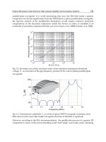
Fig. 21. Robot moving from eye-30 to obstacles free eye-60
Fig. 22. Obstacles appear in eye-60
Advances in Robot Navigation
202
Fig. 23. Robot passing obstacle area in eye-60
Fig. 24. Robot passed obstacles area in eye-60 and move to eye-50
A Distributed Mobile Robot Navigation by Snake Coordinated Vision Sensors
203
Fig. 21, Fig. 22, Fig. 23 and Fig. 24 show the real time experiments of robot control by the
mosaic eye. Each figure displays four views from each of the four eyes. Let eye-30, eye-40,
eye-50 and eye-60 be the names of the mosaic eye starting from top-right one and counting
anti-clockwise. In Fig. 21, the robot is controlled by eye-30 heading to the control area of eye-
60. The sparse white circles with numbers in the centre represent the desired path that the
robot should follow. The white rectangle blobs represent dynamic obstacles. As one can see
in Fig. 21, the dynamic obstacles are within the views of eye-30, eye-40 and eye-50 but out of
sight of eye-60. In Fig. 22, an obstacle appears within the sight of eye-60. At this point, the
robot is under the control of eye-30 and eye-30 does not know the existence of the new
obstacle. With the information sent from eye-60 notifying eye-30 of the obstacle, the
predictive path is updated to avoid the obstacle. In Fig. , the robot control is handed over
from eye-30 to eye-60. The figure shows that with the predictive path updated by eye-30 and
with the control of eye-60, the robot has successfully avoided the obstacle and continued to
move along the updated predictive path.
8. Conclusion
As an attempt to steer away from developing an autonomous robot with complex
centralised intelligence, this chapter proposes a scheme offering a complete solution for
integrating communication with path planning, trajectory generation and motion control of
mobile robots in an intelligent environment infrastructure where intelligence are distributed
in the environment through collaborative vision sensors mounted in a physical architecture,
forming a wireless vision sensor network, to enable the navigation of unintelligent robots
within that physical architecture through distributed intelligence. A bio-mimetic snake
algorithm is proposed to coordinate the distributed vision sensors for the generation of a
collision free R-snake path during the path planning process. Segments of a path distributed
in individual sensors from a start position to a goal position are described as an elastic band
emulating a snake. By following the R-snake path, an A-snake method that complies with
the robot's nonholonomic constraints for trajectory generation and motion control is
introduced to generate real time robot motion commands to navigate the robot from its
current position to the target position. A rolling window optimisation mechanism subject to
control input saturation constraints is carried out for time-optimal control along the A-
snake.
The scheme has been verified by the development of a complete test bed with vision sensors
mounted on a building ceiling. Results obtained from the experiments have demonstrated
the efficiency of the distributed intelligent environment infrastructure for robot navigation.
9. References
Arkin (2000). Behavior-based Robotics. Cambridge, MIT Press.
Cameron (1998). Dealing with Geometric Complexity in Motion Planning. New York, Wiley.
Cheng, Hu, et al. (2008). A distributed snake algorithm for mobile robots path planning with
curvature constraints. IEEE Int. Conf. on SMC, Singapore.
Cheng, Jiang, et al. (2010). A-Snake: Integration of Path Planning with Control for Mobile
Robots with Dynamic Constraints. ICCAE.
Cormen, Leiserson, et al. (2001). Introduction to Algorithms, MIT Press and McGraw-Hill.
Advances in Robot Navigation
204
Kass, Witkin, et al. (1988). Snake: Active contour models. International Journal of Computer
Vision 1(4): 321-331.
Land and Nilsson (2002). Animal Eyes, Oxford University Press.
Li and Rus (2005). Navigation protocols in sensor networks. ACM Trans. on Sensor Networks
1(1): 3-35.
Maciejowski (2001). Predictive control with constraints.
Mclean (1996). Dealing with geometric complexity in motion planning. Int. Conf., IEEE in
Robotics and Automation.
Mclean and Cameron (1993). Snake-based path planning for redundant manipulators.
Robotics and Automation, IEEE International Conference on, Atlanta, USA.
Murphy (2000). Introduction to AI robotics. Cambridge, MIT Press.
Quinlan (1994). Real-time modification of collision-free paths. Department of Computer
Science, Stanford. PhD.
Quinlan and Khatib (1993). Elastic bands: connecting path planning and control. IEEE Int.
Conf. Robotics and Automation, Atlanta, USA.
Sinopoli, Sharp, et al. (2003). Distributed control applications within sensor networks.
Proceedings of IEEE.
Snoonian (2003). Smart buildings. IEEE Spectrum 40(8).
Website (2006).
Xi and Zhang (2002). Rolling path planning of mobile robot in a kind of dynamic uncertain
environment. Acta Automatica Sinica 28(2): 161-175.
Zhang (2008). TOS_MAC Driver based on CC2420 radio chip.
Part 4
Social Robotics
10
Knowledge Modelling in Two-Level Decision
Making for Robot Navigation
Rafael Guirado, Ramón González, Fernando Bienvenido and
Francisco Rodríguez
Dept. of Languages and Computer Science, University of Almería
Spain
1. Introduction
In recent years, social robotics has become a popular research field. It aims to develop robots
capable of communicating and interacting with humans in a personal and natural way.
Social robots have the objective to provide assistance as a human would do it. Social robotics
is a multidisciplinary field that brings together different areas of science and engineering,
such as robotics, artificial intelligence, psychology and mechanics, among others (Breazeal,
2004). In this sense, an interdisciplinary group of the University of Almería is developing a
social robot based on the Peoplebot platform (ActivMedia Robotics, 2003). It has been
specifically designed and equipped for human-robot interaction. For that purpose, it
includes all the basic components of sensorization and navigation for real environments.
The ultimate goal is that this robot acts as a guide for visitors at our university (Chella et al.,
2007). Since the robot can move on indoor/outdoor environments, we have designed and
implemented a two-level decision making framework to decide the most appropriate
localization strategy.
Knowledge modelling is a process of creating a model of knowledge or standard
specifications about a kind of process or product. The resulting knowledge model must be
interpretable by the computer; therefore, it must be expressed in some knowledge
representation language or data structure that enables the knowledge to be interpreted by
software and to be stored in a database or data exchange file. CommonKADS is a
comprehensive methodology that covers the complete route from corporate knowledge
management to knowledge analysis and engineering, all the way to knowledge-intensive
systems design and implementation, in an integrated fashion (Schreiber et al., 1999).
There are several studies on the knowledge representation and modelling for robotic
systems. In some cases, semantic maps are used to add knowledge to the physical maps.
These semantic maps integrate hierarchical spatial information and semantic knowledge
that is used for robot task planning. Task planning is improved in two ways: extending the
capabilities of the planner by reasoning about semantic information, and improving the
planning efficiency in large domains (Galindo et al., 2008). Other studies use the
CommonKADS methodology, or any of its extensions, to model the knowledge; some of the
CommonKADS extensions that have been used in robotics are CommonKADS-RT, for real
time systems, and CoMoMAS (Conceptual Modelling of Multi-Agent Systems), for multi-
Advances in Robot Navigation
208
agent systems. The first one is based on CommonKADS with the addition of necessary
elements to model real time restrictions and it is applied to the control of autonomous
mobile robots (Henao et al., 2001). The second one extends CommonKADS towards Multi-
Agent Systems development. A Nomad200 mobile robot is used to analyse two agent
architectures, AIbot and CoNomad, by reverse engineering and to derive conceptual
descriptions in terms of agent models (Glaser, 2002). Nowadays the knowledge engineering
focuses mainly on domain knowledge, using reusable representations in the form of
ontologies (Schreiber, 2008).
One fundamental task to achieve our goal is robot navigation, which includes the subtasks
of path planning, motion control, and localization. Generally, in the process of developing
robots, robotics engineers select, at design time, a single method (algorithm) to solve each of
these tasks. However, in the particular case of social robots (usually designed with a generic
purpose, since its ultimate goal is to act as a human) it would be more interesting to provide
several alternatives to solve a specific task and the criteria for selecting the best solution
according to the current environment conditions. For instance, for the specific task of
localization, the robot could decide to use a GPS-like solution, if it is moving on an open
space, or dead-reckoning if it is in an indoor environment.
The main contribution of this work is the development of an operational knowledge model
for robot navigation. This model leads to a generic and flexible architecture, which can be
used for any robot and any application, with a two-level decision mechanism. In the first
level, the robotics engineer selects the methods to be implemented in the social robot. In the
second level, robot applies dynamic selection to decide the proper method according to the
environment conditions, taking into account a suitability criteria table. Dynamic selection of
methods (DSM) lets to choose the best alternative to perform a task. It uses several
suitability criteria, criterium weights, selection data and knowledge, and an aggregation
function to make the decision (Bienvenido et al., 2001).
The chapter is organized as follows. The second section presents the description of the robot
system used in this work. In the third section, the methodology for the knowledge
representation based on DSM is shown. Next, the fourth section shows the knowledge
modelling for the localization subsystem needed to develop the generic multi-agent system
for the social robot Peoplebot. The next section discusses the results of a physical experiment
carried out to analyze the proposed methodology. The last section is devoted to conclusions
and further works.
2. System description
In this work, the mobile robot called Peoplebot of ActivMedia Robotics Company has been used
to test through physical experiments the proposed decision making approach. It is a mobile
robot designed and equipped specifically for human-robot interaction research and
applications. It includes all the basic components of sensorization and navigation in real
environments, which are necessary for this interaction (see Fig. 1). It has two-wheel
differential with a balancing caster and it feeds on three batteries that give an operational
range of about ten hours. It also has installed a touch screen which displays a map of the
University of Almería. Furthermore, for speech communication, it has two microphones to
capture voice and two speakers. In this way, a user can interact with the robot either by
manually selecting a target in the touch screen showing the environment map or by
speaking directly to the robot.