Automation and Robotics Part 11 pptx
Bạn đang xem bản rút gọn của tài liệu. Xem và tải ngay bản đầy đủ của tài liệu tại đây (2.8 MB, 25 trang )
Automation and Robotics
244
developing specific software, written in a procedural language like PASCAL,
BASIC or C, to
solve each particular problem. However, the use of procedural languages brings the
following well known disadvantages: the development time of the programs is very long
and the programs are very complex, hence difficult to maintain and adapt to rapid changes
of requirements.
Unlike traditional approaches, CLP provides for a natural representation of heterogeneous
constraints and allows domain-specific heuristics to be used on top of generic solving
techniques.
3. Declarative programming – SQL, CLP
Declarative programming is a term with two distinct meanings, both of which are in current
use. According to one definition, a program is ‘declarative’ if it describes what something is
like, rather than how to create it. For example, HTML, XML web pages are declarative
because they describe what the page should contain — title, text, images — but not how to
actually display the page on a computer screen. This is a different approach from imperative
programming languages such as PASCAL, C, and Java, which require the programmer to
specify an algorithm to be run. In short, imperative programs explicitly specify an algorithm
to achieve a goal, while declarative programs explicitly specify the goal and leave the
implementation of the algorithm to the support software (for example, an SQL select
statement specifies the properties of the data to be extracted from a database, not the process
of extracting the data).
According to a different definition, a program is ‘declarative’ if it is written in a purely
functional programming language, logic programming language, or constraint
programming language. The phrase "declarative language" is sometimes used to describe all
such programming languages as a group, and to contrast them against imperative
languages.
These two definitions overlap somewhat. In particular, constraint programming and, to a
lesser degree, logic programming, focus on describing the properties of the desired solution
(the what), leaving unspecified the actual algorithm that should be used to find that solution
(the how). However, most logic and constraint languages are able to describe algorithms and
implementation details, so they are not strictly declarative by the first definition.
Constraint Logic Programming (CLP) is a declarative modelling and procedural
programming environment that integrates qualitative /heuristic knowledge representation
of logic and quantitative/algorithmic reasoning into a single paradigm. Unlike traditional
approaches, CLP provides for a natural representation of heterogeneous constraints and
allows domain-specific heuristics to be used on top of generic solving techniques. The main
issue for the constrained-based approach is CSP (Constraint Satisfaction Problem). In
artificial intelligence and operation research, constraint satisfaction is the process of finding
a solution to a set of constraints. Such constraints express allowed values for variables. A
solution is therefore an evaluation of these variables that satisfies all constraints. Constraint
Satisfaction Problems (on finite domains) are typically solved using a form of search. The
most used techniques are variants of backtracking, constraint propagation and local search.
CLP as a declarative modelling and procedural programming environment is increasingly
realized as an effective tool for decision support systems (Bisdorff & Laurent, 1995; Lamma
et al., 1997; Lee & Lee 1996). Constraint Logic Programming is suitable for Decision Support
Systems (DSS) because (Liao et al., 2002; Ryu, 1998):
A Declarative Framework for Constrained Search Problems in Manufacturing
245
• CLP is a very good tool for the development of knowledge base that has expertise and
experience represented in terms of logic, rules and constraints. This tool allows the
knowledge base to be built in an incremental and accumulating way (it is suitable for
ill-structured or semi-structured decision analysis problems).
• Constraints naturally represent decisions and their inter-dependencies. Decision choices
are explicitly modelled as the domains of constraint variables.
• CLP can serve as a good integrative environment for the decision analysis that has
different kinds of model.
Decision analysis requires a number of computational facilities which this tool can provide.
4. Declarative framework for constrained search problems
There is a growing need for decision support tools capable of assisting a decision maker in
the constrained search problems in manufacturing. The most important of them are
scheduling problems and scheduling problems with resource allocation. The diversity of
scheduling problems, the existence of many specific constraints (precedence, resource,
capacity, etc.) in each problem and the efficient constraint based scheduling algorithms
make constraint logic programming a method of choice for the resolution of complex
practical problems. In constraint programming approach to decision support in scheduling
problems, the problem to be solved is represented in terms of decision variables and
constraints on these variables (Pape, 1995).
Depending on the particular applications, the variables of scheduling problems (job-shop,
flow-shop, open-shop, and project shop) can be:
• The start time and the end time of each operation.
• The set of resources assigned to each operation (if this set is not fixed).
• The capacity of a resource that is assigned to an operation (e.g. the number of workers
from a given team assigned to operation).
• The processing times (constant, variable increasing/decreasing function of starting
times or allocated resources, etc.).
The constraints of a scheduling problem include:
• Temporal and precedence constraints which define the possible values for the start and
end times of operations and the relations between the start and end time of two
operations.
• Resource constraints which define the possible set of resources for each operation.
• Capacity constraints which limit the available capacity of each resource over time.
• Problem-specific constraint which correspond to particular features of operations and
resources.
Additional variables and constraints can be included to represent optimization criteria,
preferences of the user of scheduling system, etc.
4.1 Assumptions of DSS based on declarative framework
The presented in (section 3) advantages and possibilities of CLP environment for decision
support make it interesting for decision support in constrained search problems. Building
decision support system for scheduling, covering a variety of production organization
forms, such as job-shop, flow-shop, project, multi-project etc., is especially interesting.
The following assumptions were adopted in order to design the presented scheduling
processes of decision support system (see Fig. 1.):
Automation and Robotics
246
• Problem-specific constraint which correspond to particular features of operations and
resources.
• The system should possess data structures that make its use possible in different
production organization environments (see Fig. 2.).
• The system should make it possible to schedule the whole set of tasks/jobs
simultaneously, and after a suitable schedule has been found, it should be possible to
add a new set of tasks later, and to find a suitable schedule for both sets without the
necessity to change initial schedules.
• The decisions of the systems are the answers to appropriate questions formed as CLP
predicates.
• The system should regard:
o additional resource types apart from machines, e.g. people, tools, etc,
o temporary inaccessibility of all resource types,
o resource or time depending processing times, etc.
Fig. 1. Concept of DSS for scheduling problems based on declarative framework.
The range of the decisions made by the system depends on data structures and asked
questions. Thus, the system is very flexible as it is possible to ask all kinds of questions
(write all kinds of predicates). In this version of DSS the questions which can be asked are
the following:
A Declarative Framework for Constrained Search Problems in Manufacturing
247
• What is the minimum number of workers necessary for assigned makespan and proper
schedule? (predicate opc_d(L,C)).
• What is the minimum makespan at the assigned number of workers and proper
schedule? (predicate opc_g(L,C)).
• Is it possible to order new tasks (both orders and projects) for the determined
makespan? (predicate opc_s(L,C)).
• What is minimum makespan at the assigned number of workers for new tasks?
(predicate opcd_g(L,C)).
• What is the minimum number of workers necessary for assigned makespan for new
tasks? (without changing the schedule of basic set of tasks) (predicate opcd_d(L,C)).
• Is it possible to order tasks for the determined makespan ? (predicate opcd_s(L,C)).
• Is it possible to order tasks for the determined makespan where the processing time of
task depends on allocated number of workers? (predicate opcd_s1(L,C)).
L – number of workers (manpower), C=C
max
– makespan
These questions are just examples of questions that the present system can be asked. New
questions are new predicates that need to be created in CLP environment. Two types of
questions are asked in the system:
• About the existence of the solution (eg., is it possible to carry out a new task in the
particular time?, etc.).
• About a particular kind of the solution: find a suitable schedule fulfilling the
performance index, find the minimum scheduling length-makespan, find the minimum
number of workers to carry out the task, etc.
The foregoing questions can include a random set of additional renewable resources (in this
case, workers only) and refer a random number of production organization forms (job-shop,
flow-shop, open-shop, project etc.). Additionally, the presented decision support system
model implements an extra functionality which is resource dependent processing times.
Scheduling problems literature gives the processing time as constant and defined before the
tasks are realized. In practical applications the time is significantly dependent on the
amount of the allocated resources for their realization. These dependencies are usually non-
linear and can be presented as a relationship (relational database table) or function. The
system implemented the possibility of changing the time of task/job realization in relation
to the allocated number of workers. The functionality above does not call for the change of
predicates; it requires suitably prepared data describing the problem and included in the
relational database. The proposed structure of the relational database (see Fig. 2.) and the
way CLP predicates are built allow the system to generate both schedules with determined
parameters for different production organization forms, but also include allocation of
additional resources (in general case resource sets) and effects they may have on the realized
tasks.
4.2 Data structures
Data structures were designed in such a way that they could be easily used to decision
problems in a variety of scheduling environments, which is job-shop, flow-shop, project or
multi-project. The obtained flexibility resulted from the use of a relational data model.
Automation and Robotics
248
Figure 2 presents the ERD (Entity Relationship Diagram) of the database that was designed
to meet the requirements of cooperation with CLP environment and to have the following
possibilities:
• Storing the data for scheduling problems and resource allocation for different types of
production organisation.
• Storing information about additional resources (e.g. labour force, tools or AGV
vehicles).
• Saving the content and parameters of CLP predicates calls.
• Generating ready scripts for a CLP engine on the basis of the existing data.
• Saving the results obtained with a CLP solver, necessary for further calculations,
visualisations or creating reports.
• Saving data about other problems within the family of constrained search problems.
Fig. 2. Schema of database of DSS for production scheduling problems (Entity Relationship
Diagram).
A Declarative Framework for Constrained Search Problems in Manufacturing
249
Fig. 2b. Schema of the part of database of DSS for an automatic generation CLP predicates
(Entity Relationship Diagram).
Table 1 shows the description of database structure.
Table name Table description Column Column description
id_t project_type_id
Project_types
The types of possible
projects for realization
type_name project_type_name
id_f project_id
name project_name
Projects
The specification of
separate projects in
enterprises
id_t project_type_id
id_c_f function_id
name function_name
Processing_time
s
The list of functions of
time calculation
body function_body
id_o_t operation_type_id
name operation_type_name
Opertaion_types
The list of operation
types
id_c_f function_id
id_f project_id
id_o operation_id
id_o_t operation_type_id
name operation_name
t_z release time
t_k critical time
Operations
The list of operations to
be realized
start start time
id_f project_id
id_o_p operation_id
id_o_d operation_id
Precedence
Defines the sequence of
the realized operations
time time between operations
id_f project_id
id_m machine_id
Machines
The specification of
available machines for
the operation realization
name machine_name
id_f project_id
id_o operation_id
id_m machine_id
Allocations
The allocation of
operation to machines
id_c_p parameters_of_function
id_f project_id
id_z resource_id
name resource_name
Resources
The specification of
renewable/external
resources
limitation resource_limitation
Automation and Robotics
250
Table name Table description Column Column description
id_f project_id
id_o operation_id
id_z resource_id
p_min
min number of allocated
resource
p_max
max number of allocated
resource
id_c_p parameters_of_function
Allocations_R
The allocation of
renewable/external/
additional resources to
operations
number_r number of allocated resource
id_f project_id
id_k period_number
Calendar
The specification of
planning/scheduling
periods
date starting_date
id_f project_id
id_m machine_id
id_k_p number of initial period
Inaccessibility_
of_machines
The specification of
inaccessibility of
machines
id_k_k number of final period
id_f project_id
id_z resource_id
id_k_p number of initial period
id_k_k number of final period
Inaccessibility_
of_resources
The specification of
limitation/inaccessibilit
y of resources
accessibility number of accessible resources
id_l line generation type
type type description
Type_lines
function function (in script language)
id_f project_id
step number of generation step
id_l line generation type
Gener
Describes the process of
model generation for
Eclipse
lines line to be made
id_f project_id
name name of predicate
Eclipse_predicates
The codes for the ready
predicates of Eclipse
body code of predicate
login login
password password
Users
id_f project_id
Table 1. Description of database structure.
5. Implementation of DSS based on declarative framework
We propose ECL
i
PS
e
(, 2008, Apt & Wallace, 2007) and SQL
database as a platform to decision support in scheduling problems. ECL
i
PS
e
is a software
A Declarative Framework for Constrained Search Problems in Manufacturing
251
system - based on the CLP paradigm - for the development and deployment of constraint
programming applications. It is also ideal for developing aspects of combinatorial problem
solving, e.g. problem modelling, constraint programming, mathematical programming, and
search techniques. Its wide scope makes it a good tool for research into hybrid problem
solving methods. ECL
i
PS
e
comprises several constraint solver libraries, a high-level
modelling and control language, interfaces to third-party solvers, an integrated
development environment and interfaces for embedding into host environment. The
ECL
i
PS
e
programming language is largely backward-compatible with Prolog and supports
different dialects.
The novelty of the proposed approach is in the integration of the CLP methodology with a
commonly used relational database model. The scripts started by a CLP engine are
generated automatically on the basis of data in the database (numerical values and CLP
predicates). The proposed solution makes it possible to easily develop the system
(developing and saving in the database the content of additional CLP predicates) and to
integrate it with other computer systems based on a relational SQL database (Fig. 3.). Owing
to the developed database structure (see Fig. 2.) solving other problems of the constrained
search problems class is possible. In order to ensure an automatic generation of the
production scheduling problem model in the form of a script with CLP predicates, two
additional tables were added to the database (Fig. 2b). The gener table describes the model
schema as lines containing the model’s identity (id_f), generating step (step) and the identity
of the line type that is to be written in the CLP script (id_l) with its source (lines). The type of
the generated line is determined from the entry in the table type lines. The model (CLP
script) distinguishes lines created among others as inserting CLP predicate (line in the
eclipse_predicates table), inserting data after SQL statement, inserting a comment, heading,
etc; thus the relation between tables gener and type_lines is 1:N type (Fig. 2b.).
Fig. 3. Implementation of the declarative framework of DSS.
Automation and Robotics
252
6. Illustrative examples
After the complete implementation of the DSS into ECL
i
PS
e
and SQL environments,
computation experiments were carried out. The job-shop scheduling problem with
manpower resources (Example 1) and project –building house (Example 2) were considered.
The proposed illustrative examples cover a wide range of scheduling problems encountered
in the SMEs (Small and Medium Sized Enterprises). The examples are selected in such a way
that they how two extremely different forms of production organization; repetitive
production in the job-shop environment and the unique production including the project.
The presented methodology makes solving scheduling problems possible also in indirect
methods of production organization. Moreover, the examples are larded with problems of
constrained resources (e.g. manpower, specialized machines, etc.) and the dependence of
particular jobs processing time on the amount of the allocated resources, for instance
6.1 Example 1- the job shop scheduling
In the classical scheduling theory job processing times are constant (Example_1a). However,
there are many situations where processing time of a job depends on the starting time of the
job in queue or the amount of allocated additional resources (e.g. people) (Example_1b) etc.
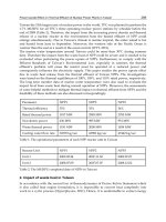
The parameters of computational examples are presented in table 2. The job data structures
are shown in Fig. 4a and Fig. 4b
Fig. 4a. Description of task (job) data structure for job-shop computational example
(Example_1a) – the constant processing times.
Fig. 4b. Description of task (job) data structure for job-shop computational example
(Example_1b) – the processing times depend on allocated number of workers.
j∈{A,B,C,D,E}, o∈{1,2,3,4,5}, s∈{1,2,3,4,5}
j=A [(1,10,2), (2,20,2), (3,15,3), (4,15,2), (5,15,1)]
j=B[(1,10,1), (2,20,1), (3,15,2), (4,15,1), (5,20,1)]
j=C[(5,15,2), (4,20,2), (3,15,1), (2,10,2), (1,20,2)]
j=D[(1,10,3), (3,15,2), (2,20,2), (4,20,1), (5,10,2)]
j=E[(5,15,2), (4,10,1), (3,15,2), (2,10,2), (1,20,1)]
Table 2. (Example_1) – constant processing times
A Declarative Framework for Constrained Search Problems in Manufacturing
253
For the computational example (Example_1a) the following questions (write following
predicates) were asked:
• opc_g(_,_) (see Fig. 5.).
• opc_d(_, 120) (see Fig. 6.).
• opc_s(4,155) (see Fig. 7.).
• opc_s(4,180) (see Fig. 8.).
• opc_g(5,_) (see Fig. 9.).
Fig. 5. Gantt’s charts for the answer to the question implemented in predicate opc_g(_,_),
C
max
*=120, L=7 (Example_1a).
Fig. 6. Gantt’s charts for the answer to the question implemented in predicate opc_d(_,120),
L
min
=6, C
max
= C
max
* =120 (Example_1a).
Automation and Robotics
254
Fig. 7. Answer to the question implemented in predicate opc_s(4,155) – No (Example_1a).
Fig. 8. Answer to the question implemented in predicate opc_s(4,170) – Yes (Example_1a).
Fig. 9. Gantt’s charts for the answer to the question implemented in predicate opc_g(5,_),
C
max
*=135, L=5 (Example_1a).
Predicate L C
max
Yes No Time (s)
1
Opc_g(_,_)
7 120 0,13
2
Opc_d(_,120)
6 120 0,35
3
Opc_s(4,155)
4 155 NO 0,02
4
Opc_s(4,170)
4 170 YES 0,25
5
Opc_g(5,_)
5 135 1,35
Table 3. (Example_1a) – Results of asked predicates (Fig.5-9).
A Declarative Framework for Constrained Search Problems in Manufacturing
255
The second version of computational example (Example_1b) was carried out with
processing times of operation/activity dependent on allocated additional resource
(workers). The parameters of computational Example_1b are presented in table 2 without
processing times and number of allocated people. The processing time is a function of
allocated workers f(p
j
,a
j
,u
j
) Fig. 10.
f(p
j
,a
j
,u
j
) = p
j
– a
j
*(u
j
- x
j
)
and
f(p
j
,a
j
,u
j
) > 0 ,
a
j
=5, x
j
≤
u
j
≤2*x
j
where :
p
j
- processing time from Example_1
u
j
- number of allocated workers
x
j
- number of allocated workers from Examle_1a
a
j
- acceleration factor
Fig. 10. Processing time for Example_1b.
There is a simple linear function in this example. It can be any function in general case or
relationship (relational database table). For the computational example (Example_1b) the
following questions (write following predicates) were asked:
• opc_g(_,_) (see Fig. 11.).
• opc_s(8,80) (see Fig. 12.).
• opc_d(_,60) (see Fig. 13.).
• opc_s(6,60) (see Fig. 14.).
Fig. 11. Gantt’s charts for answer to the question implemented in predicate opc_g(_,_),
C
max
*=65, L=14 (Example_1b).
Automation and Robotics
256
Fig. 12. Answer to the question implemented in predicate opc_s(8,80) – Yes (Example_1b).
Fig. 13. Gantt’s charts for answer to the question implemented in predicate opc_d(_,65),
L
min
=10, C
max
= C
max
* =65 (Example_1b).
Fig. 14. Answer to the question implemented in predicate opc_s(6,60) – No (Example_1b).
A Declarative Framework for Constrained Search Problems in Manufacturing
257
Predicate L C
max
Yes No Time (s)
1
Opc_g(_,_)
13 65 0,14
2
Opc_d(_,65)
10 65 17,84
3
Opc_s(8,80)
8 80 YES 0,64
4
Opc_s(6,60)
6 60 NO 0,05
Table 4. (Example_1b) – Results of asked predicates (Fig.11-14).
6.1 Example 2- Project scheduling – building a house
A typical modern-day project has a variety of complications not considered in the original
PERT/CPM methodology. There are three particular situations:
• You may be able to accelerate the completion of a project by speeding up or “crashing”
some of the activities in the project.
• Your ability to finish a project quickly is hindered by limited resources (e.g., two
activities that might otherwise be done simultaneously, in fact have to be done
sequentially because they both require a crane and you have only one crane on site).
• How long it takes to do each activity is a random variable.
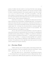
In table 5, we list the activities involved in a simple, but nontrivial, project of building a
house. An activity cannot be started until all of its predecessors are finished. The network
activity for this project has been shown in Fig. 15. To solve this example the DSS with
declarative programming (section 4) was used. In this example the processing times of
activities depend on allocated manpower resource.
On. Activity Time Min_MAN Max_MAX Name of activity
1 10 2 2 Dig Basement
2 12 4 6 Pour Foundation
3 6 1 3 Pour Basement
4 6 2 3 Install Floor Joists
5 6 1 3 Install Walls (ext)
6 4 2 8 Install Rafters
7 4 2 4 Install Walls (int)
8 4 2 2 Install Roof
9 16 4 8 Install Windows, Doors (ext)
10 12 4 8 Install Networks
11 12 6 8 Interior Plastering
12 4 2 4 Painting (int)
13 6 2 3 Finish Interior
14 18 6 9 Finish Terrace
15 4 2 4 Garden Arrangement
16 18 6 12 Exterior Plastering
MIN_MAN – minimum manpower (workers) for activity.
MAX_MAN – maximum manpower (workers) for activity.
Table 5. Parameters of Example_2
Automation and Robotics
258
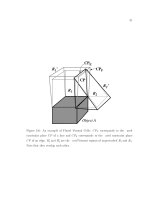
Fig. 15. Activity network for Example_2.
For the computational example the following questions (write following predicates) were
asked (see section 4):
• opc_g(150,200 (see Fig. 16., Table 6,7).
• opc_g(5,400) (see Fig. 17., Table 6,7).
• opc_g(7,200) (see Fig. 18., Table 6,7).
• opc_g(12,200) - processing times of jobs dependent on the allocated additional resource
(workers) (see Fig. 19., Table 6,7).
Fig. 16. Answer to the question implemented in predicate opc_g(150,200) – Yes (Example_2).
Fig. 17. Answer to the question implemented in predicate opc_g(5,400) – No (Example_2).
Fig. 18. Answer to the question implemented in predicate opc_g(7,200) – Yes (Example_2).
A Declarative Framework for Constrained Search Problems in Manufacturing
259
Fig.19. Answer to the question implemented in predicate opc_g(12,200)– Yes (Example_2).
On. Predicate L C Yes No Time (s)
1
Opc_g(150,200)
8 112 YES 0,05
2
Opc_g(5,400)
5 400 NO 0,00
3
Opc_g(7,200)
6 128 YES 0,44
4
Opc_g(12,200)
12 89 YES 0,03
Table 6 (Example_2) Results of asked predicates (Fig.16-19).
On. Opc_g(150,200) Opc_g(5,400) Opc_g(7,200) Opc_g(7,200)
1 0 0 0 (2)
2 10 10 10 (6)
3 22 22 20 (3)
4 28 2 24 (3)
5 28 28 24 (3)
6 34 34 28 (3)
7 34 34 29 (4)
8 38 38 31 (2)
9 42 42 35 (8)
10 42 58 35 (4)
11 58 70 47 (8)
12 70 82 57 (2)
13 70 82 57 (3)
14 76 88 62 (9)
15 76 106 62 (2)
16 94 110 77 (12)
Table 7 (Example_2) Result of asked predicates-start times of activities (additional number
of allocated workers- only for predicate Opc_g(7,200)).
The results obtained for illustrative examples confirm suitability of the proposed framework
for building decision support systems in constrained search problems. In scheduling
problems the decision maker is provided with support related to possibilities of task
accomplishment in the set time, necessary resources and their exploitation in time,
possibilities of the realization of other tasks, decision optimization, etc.
Automation and Robotics
260
7. Conclusions
The proposed approach can be considered to be a contribution to scheduling and especially
to scheduling problems with additional/external resources. In many enterprises this kind of
resources can have an influence on production and delivery schedules. That is especially
important in the context of cheap, fast and user friendly decision support in SMEs. Great
flexibility of the presented approach and practically unlimited possibilities of asking
questions through creating predicates cannot be overestimated. What is more, the whole
decision system can be built in one modeling and programming declarative environment,
which lowers costs and adds to the solution effectiveness. The CLP-tools fulfill the need of
intelligent production management structures and can be based successfully in cases of
scheduling problems with external resources. The proposed approach seems to be a viable
alternative option for supporting quite a number of decision making processes. The
originality of our approach, which achieves the transition from custom imperative
programming to declarative programming in a field of scheduling problems, consists in the
data structure and CLP implementation. The presented framework can be implemented in
many other constrained search problems apart from scheduling such as planning, routing,
placement etc.
8. References
Liao S.Y., Wang H.Q., Liao L.J. “An extended formalism to constraint logic programming for
decision analysis, Knowledge-based Systems” 15, 2002, pp 189-202.
Pape C.Le “Three Mechanisms for Managing Resource Constraints in a Library for
Constraint-Based Scheduling Proceedings” INRIA/IEEE Conference on Emerging
Technologies and Factory Automation, 1995.
Ryu U. Young .”Constraint logic programming framework for integrated decision supports”
Decision Support Systems 22, 1998, pp 155-170.
Bisdorff R., Laurent S. “Industrial linear optimization problem solved by constraint logic
programming”, European Journal of Operational Research 84 (1), 1995, pp 82-95.
Lamma E., Mello P., Milano M. “A distributed constrained-based scheduler”, Artificial
Intelligence in Engineering 11,1997, pp 91-105.
Lee H.G., Lee G. Yu., “Constraint logic programming for qualitative and quantitative
constraint satisfaction problems”, Decision Support Systems 16 (1), 1996, pp 67-83.
Apt K.R., Wallace M.G. “Constraint Logic Programming using ECL
i
PS
e
“, Cambridge, 2007
15
Derivation and Calculation of the
Dynamics of Elastic Parallel Manipulators
Krzysztof Stachera and Walter Schumacher
Technical University of Braunschweig, Institute of Control Engineering
Germany
1. Introduction
Many algorithms for the modelling and calculation of the dynamics of rigid parallel
manipulators already exist, and are based on two approaches: The Newton-Euler method
and the Lagrangian principle. For the Newton-Euler method the dynamics equations are
generated by the complete analysis of all forces and torques of each rigid body in the robot’s
structure (Featherstone & Orin, 2000, Spong & Vidyasagar, 1989). Therefore, the derivation
of the equations of motion for complex systems becomes very complicated and laborious.
However, due to the fact that all forces are explicitly regarded and analysed, this method
supplies a very advanced understanding of the system’s dynamics. The use of the
Lagrangian principle is a much more elegant and efficient procedure. A scalar function
called the Lagrangian is generated, and describes the entire kinetic, potential and dissipative
energy of the system in generalized coordinates. For parallel manipulators, additional
equations which describe the closed kinematic loop constraints, still have to be provided.
The equation of motion for the parallel structure consists thus of the system of Lagrange and
algebraic equations (DAE).
The Lagrangian method is very widely used in the area of parallel manipulators (Beyer,
1928, Kock, 2001). In particular, two procedures from this family are established here:
Namely the Lagrangian equations of the first type (Kang & Mills, 2002, Miller & Clavel,
1992, Murray et al., 1994, Tsai, 1999) and the Lagrange-D’Alembert formulation (Nakamura,
1991, Nakamura & Ghodoussi, 1989, Park et al., 1999, Stachera, 2006a, Stachera, 2006b, Yiu et
al., 2001). The use of generalized coordinates is employed in these procedures. Those being
the coordinates of the active joints as well as an additional set of redundant coordinates of
the passive non-actuated joints or end-effector coordinates. Active joints are the actuated
joints of the machine. In the case of elastic manipulators a set of elastic degrees of freedom
(DOF) will be introduced. In these generalized coordinates the energy function will be
formulated. Additionally, the closed kinematic loop constraints of the parallel structure
must also be considered. In the Lagrangian equations of the first type this is achieved by
Lagrange multipliers. Contrary to these equations, for the Lagrange-D’Alembert
formulation, the Jacobian matrices of the kinematic constraints parameterised by the non-
redundant coordinates are used. The policy with the Jacobian matrix has the great
advantage that the well known methods and techniques for the modelling of the
manipulator’s chain dynamics, which were already applied to serial elastic robots can be
Automation and Robotics
262
used (Khalil & Gautier, 2000, Piedboeuf, 2001, Robinett et al., 2002). In this way, effects of
friction, elasticities, etc. can be considered by the modelling of the dynamics without
laborious modifications. This procedure provides compact equations of the manipulators
dynamics, which is advantageous for system analysis and control design. The problem
arises with the calculation of the direct dynamics of both presented approaches; it requires
the inversion of the inertia matrix, which can be CPU-intensive for matrices of higher order
and can thereby constitute a limitation in the real-time calculation for control purposes. The
consideration of the manipulator’s elasticities can introduce matrices of such high order. The
partitioning of the dynamics equations into many groups and their calculation in parallel
can reduce the computational effort. Approaches, which consider this problem can be found
in the literature. A virtual spring approach has been proposed for this type of parallel
processing (Wang & Gosselin, 2000, Wang et al., 2002). In this method, the modelling
technique requires the modification of the model and the introduction of additional
elements. In the case of elastic manipulators it seems to be a not desirable procedure.
Firstly this chapter presents a brief description of the two above mentioned Lagrangian
based methods. It will be shown, how the equations of the inverse and direct dynamics can
be obtained, subsequently, the main features of these methods are discussed. These
formulations will be extended in comparison with previous research to consider the elastic
degrees of freedom. The presentation of elasticities as discrete degrees of freedom does not
introduce any limitations of the method and is a conventional method for the analysis of
elastic robots (Beres & Sasiadek, 1995, Robinett et al., 2002). In addition to that, a new
method for the derivation of the Jacobian matrix of the parallel manipulators will be
presented (Stachera & Schumacher, 2007). This method allows the Jacobian matrix of the
parallel manipulator to be derived systematically from the Jacobian matrices of the
individual serial kinematic chains. Based on these procedures, the method - Simultaneous
Calculation of the Direct Dynamics (SCDD) for elastic parallel manipulators will be presented.
The idea of the “reduced system”, which was already used to calculate the inverse
dynamics, will be considered. The kinematic constraints of the closed loops are introduced
here with the help of the forces and torques of the tree structure. Therefore the equations
remain simple and their complexity should not rise. This feature is very important for
simulations, for the application of an observer for complex systems or in a feedback control.
The new method will then be compared with the existing one and the results will be
discussed thereafter.
2. Lagrangian equations of the first type
The Lagrangian equations of the first type are formulated in a set of redundant coordinates
(Kang & Mills, 2002, Miller & Clavel, 1992, Tsai, 1999). We assume that the manipulator
possesses in all n joints, e and p of them are respectively discrete elastic DOF and passive
joints as redundant coordinates. All of which joints have one degree of freedom.
Coordinates of the end-effector or moving platform can be also used as redundant
coordinates. The coordinates of the actuated joints n
a
and the elastic DOF n
e
=e form a set of
non-redundant coordinates. We assume the controllability of the manipulator structure in
absence of elasticity. The coordinates of the structure are:
(
)
epatt
q,q,qqq = , (1)
Derivation and Calculation of the Dynamics of Elastic Parallel Manipulators
263
where
1)
a
(n
R
×
∈
a
q ,
1)
p
(n
R
×
∈
p
q ,
1)
e
(n
R
×
∈
e
q and the dimension of
1)
t
(n
R
×
∈
t
q , where n
t
=n
a
+
n
p
+n
e
. The q
t
coordinates comprise the redundant degrees of freedom of the rigid
movement of the manipulator augmented by degrees of freedom of the elastic deformation
of the robot’s structure. The redundant coordinates of the passive joints q
p
depend on the
remaining coordinates:
(
)
eapp
q,qqq = . (2)
Using (2) we can further write (1) as q
t
= q
t
(q
a
, q
e
). In order to solve the dynamics equation,
due to redundant coordinates, the formulation of dynamics requires a set of additional
constraint equations. These can be determined by examining the structure of the system,
with respect to the closed kinematic loop constraints of the parallel manipulator. The
constraints equations and their derivatives supplement the original equations of the
machine dynamics, so that the number of equations is equal to that of the unknowns.
Therefore the Lagrangian equations of the first type are formulated as follows
∑
=
∂
∂
+=
∂
∂
+
∂
∂
−
∂
∂
p
n
1i
i
i
ttt
h
λ
QLL
dt
d
t
t
ttt
q
τ
qqq
, (3)
where L
t
is the Lagrange function consists of the kinetic and potential energy of the system,
Q
t
means the function of the dissipative energy, h
i
denotes the i
th
constraint function, n
p
is
the number of constraints and at the same time number of redundant coordinates, τ
t
are the
generalised torques and forces and λ
i
are the Lagrange multipliers. In order to simplify the
solution of these equations, they will be divided into two sets (Tsai, 1999).
2.1 Inverse dynamics
The first set of n
p
equations refers to the redundant coordinates and is associated with the
kinematic constraints of the closed loops. Here, the unknowns are the Lagrange multipliers
1)
p
(n
R
×
∈
i
λ . Hence, these equations take the form
t
tttt
τ
qqqq
ˆ
QLL
dt
dh
λ
ttt
p
n
1i
i
i
−
∂
∂
+
∂
∂
−
∂
∂
=
∂
∂
∑
=
, (4)
where
t
τ
ˆ
represents generalised torques and forces. They represent the external potential
and non-potential forces, acting on the manipulator, which are already known. Here, the
torques of the actuators are not taken into account. From these n
p
equations of the
redundant coordinates the n
p
Lagrange multipliers are calculated. The second set is related
to the (n
a
+n
e
) non-redundant coordinates. The only unknowns in these equations are the
forces and torques of the actuators, which can be computed from
∑
=
∂
∂
−
∂
∂
+
∂
∂
−
∂
∂
=
p
n
1i
i
i
ttt
h
λ
QLL
dt
d
tttt
t
qqqq
τ
. (5)
With these two equation sets (4) and (5), the torques and forces of the actuators for a given
trajectory are computed, and thus produce the desired movement of the elastic parallel
manipulator.
Automation and Robotics
264
2.2 Direct dynamics
For the given torques, the direct dynamics can be computed in a similar way. The n
p
redundant coordinates and their derivatives are calculated from the closed kinematic loop
constraints h
i
and their derivatives. These redundant coordinates result from the non-
redundant coordinates of the active joints and elastic DOF. The constraint forces of the
structure are then computed (4). Finally, now that the input torques of the parallel
manipulator and the constraint forces are known, (5) must be solved for the unknown
accelerations of the non-redundant coordinates. Further, these equations can be solved by
numerical integration, and the n
p
Lagrange multipliers from (4) can also be computed on
this way.
2.3 Features of the method of the Lagrangian equations of the first type
The coordinates of the active joints and elastic DOF form a subset of the selected generalised
redundant coordinates. The remaining coordinates can be selected freely. These can be the
coordinates of the platform, the end-effector or of the passive joints (Kang & Mills, 2002,
Miller & Clavel, 1992, Tsai, 1999). Here the Lagrange multipliers might also have the
meaning of generalised torques and forces, which determine the constraints of the closed
loops for the serial kinematic chains. The disadvantage of this method is that, for the
modelling of the manipulator, various simplifications must be made. In order to consider
the Lagrange multipliers, the methods for the modelling of the dynamics that are used for
the serial kinematic chains can require a modification. However, due to the equations’
structures, a clear physical interpretation of the terms is not always possible, and therefore
the employment of this method remains slightly complicated.
3. Lagrange-D’Alembert formulation (L-D’A)
3.1 Inverse dynamics
The Lagrange-D’Alembert formulation represents an elegant and effective consideration of
the problem of manipulator’s dynamics (Nakamura, 1991, Nakamura & Ghodoussi, 1989,
Park et al., 1999, Yiu et al., 2001). Here, no additional multipliers are calculated. A set of
independent and dependent generalized coordinates which satisfy the constraints of the
mechanical system is chosen. The coordinates of the elastic DOF belong to the group of
independent coordinates and are associated with the corresponding internal forces,
resulting from the stress induced in the material. The procedure corresponds to the
methods, which are known from the serial manipulators and consists of the following three
steps:
1.
Transformation of the System: Each closed kinematic loop of the parallel manipulator is
separated at a passive joint, end-effector or link. The result is a tree structure as a
reduced system (Nakamura & Ghodoussi, 1989). Consequently, only serial kinematics
chains can be found in this system. Furthermore it is assumed that all remaining passive
joints are equipped with virtual actuators.
2.
Computation of the Torques: The torques and forces of the real and virtual actuators are
computed for each kinematic chain. These torques and forces cause a movement in
every chain, and these movements correspond to the movement of the original closed-
link structure.
3.
Transformation of the Torques: The torques and forces of the original parallel
manipulator’s actuators are calculated from the forces and torques of the tree structure
by considering the additional closed kinematic loop constraints.
Derivation and Calculation of the Dynamics of Elastic Parallel Manipulators
265
We assume that the manipulator consists of l closed kinematic loops. It possesses in all n
joints,
e and p of them are respectively discrete elastic DOF and passive joints. All of which
joints have one degree of freedom. The coordinates of the active joints and elastic DOF form
a set of non-redundant coordinates. We assume the controllability of the manipulator in
absence of elasticity. According to the first step we divide this system into a tree structure.
The number of active joints remains the same as in the original structure n
a
= (n−p−e). The
number of passive joints amounts to n
p
= (p−l) and the number of the elastic DOF amounts
to n
e
=e. The coordinates of the tree structure are:
(
)
epatt
q,q,qqq = , (6)
where
1)
a
(n
R
×
∈
e
q
,
1)
p
(n
R
×
∈
p
q ,
1)
e
(n
R
×
∈
e
q
and the dimension of
1)
t
(n
R
×
∈
t
q
, where n
t
=n
a
+
n
p
+n
e
. The redundant coordinates of the passive joints q
p
depend on the coordinates of the
active joints q
a
and the elastic DOF q
e
:
(
)
aepp
qqq = , (7)
where
1)
ae
(n
R
×
∈
ae
q and n
ae
=n
a
+n
e
. Using (7) we can further write (6) as q
t
= q
t
(q
ae
).
Generally, the relation represented in (7) does not exist analytically, but the quantity of
redundant coordinates can always be determined by the consideration of the geometrical
dependencies in the manipulator structure (Merlet, 2000, Stachera, 2005). Therefore, in order
to determine the relationship between the velocities and accelerations of the active and
passive joints, a more suitable solution must be derived (Yiu et al., 2001). For this purpose
we introduce the closed kinematic loop constraints of the parallel manipulator:
(
)
0h)h( ==
paet
q,qq . (8)
By differentiation of (8) we obtain the constraints in the Pfaffian form:
0
hh
=
∂
∂
+
∂
∂
p
T
p
ae
T
ae
q
q
q
q
. (9)
Our goal is now to find the transformation between the tree structure and the original
parallel manipulator. According to the D’Alembert principle the performed virtual work for
both systems, the reduced and the original one, has to be equal:
t
T
tc
T
c
τqτq δδ = , (10)
where
1)
t
(n
R
×
∈
t
τ
represents all forces and torques of the real and virtual drives of the tree
system and
1)
ae
(n
R
×
∈
c
τ the drive torques of the original parallel manipulator. Hence, the
Lagrange equations for the reduced system can be formulated:
0δ
QLL
dt
d
T
ttt
=
⎟
⎟
⎠
⎞
⎜
⎜
⎝
⎛
−
∂
∂
+
∂
∂
−
∂
∂
tt
ttt
qτ
qqq
, (11)
where L
t
is the Lagrange function of the tree structure and Q
t
is the function of the
dissipative energy. This Lagrange function consists of the kinetic and potential energy of the
Automation and Robotics
266
system L
t
= T
t
− V
t
. We assume that the robot is normally actuated and away from actuator
singularity. The matrix from (9) -
T
p
q∂
∂h
is square and invertible. The configuration space of
the manipulator can be smoothly parameterised by the coordinates of the active joints and
the elastic DOF q
ae
:
ae
T
ae
p
ae
T
ae
T
p
p
q
q
q
q
q
⎟
⎟
⎠
⎞
⎜
⎜
⎝
⎛
∂
∂
=
⎟
⎟
⎠
⎞
⎜
⎜
⎝
⎛
∂
∂
⎟
⎟
⎠
⎞
⎜
⎜
⎝
⎛
∂
∂
=
−
hh
1
. (12)
Therefore the equations of the tree structure can be expressed in the non-redundant
coordinates q
ae
. Considering (6), (11) and (12):
0δ
QLL
dt
d
δ
QLL
dt
d
T
ttt
T
ttt
=
⎟
⎟
⎠
⎞
⎜
⎜
⎝
⎛
−
∂
∂
+
∂
∂
−
∂
∂
+
⎟
⎟
⎠
⎞
⎜
⎜
⎝
⎛
−
∂
∂
+
∂
∂
−
∂
∂
pp
ppp
aeae
aeaeae
qτ
qqq
qτ
qqq
, (13)
and it is:
p
T
ae
p
ae
ppp
T
ae
p
aeaeae
τ
q
q
τ
qqq
q
q
qqq
T
ttt
T
ttt
QLL
dt
d
QLL
dt
d
⎟
⎟
⎠
⎞
⎜
⎜
⎝
⎛
∂
∂
+=
⎟
⎟
⎠
⎞
⎜
⎜
⎝
⎛
∂
∂
+
∂
∂
−
∂
∂
⋅
⎟
⎟
⎠
⎞
⎜
⎜
⎝
⎛
∂
∂
+
⎟
⎟
⎠
⎞
⎜
⎜
⎝
⎛
∂
∂
+
∂
∂
−
∂
∂
. (14)
The equations of motion of the entire parallel manipulator are similar to (11) and take the
following form:
c
aeaeae
τ
qqq
=
⎟
⎟
⎠
⎞
⎜
⎜
⎝
⎛
∂
∂
+
∂
∂
−
∂
∂
ccc
QLL
dt
d
. (15)
Regarding (10), (14) and (15) we can finally write:
⎟
⎟
⎠
⎞
⎜
⎜
⎝
⎛
∂
∂
+
∂
∂
−
∂
∂
⋅
⎟
⎟
⎠
⎞
⎜
⎜
⎝
⎛
∂
∂
+
⎟
⎟
⎠
⎞
⎜
⎜
⎝
⎛
∂
∂
+
∂
∂
−
∂
∂
=
∂
∂
+
∂
∂
−
∂
∂
ppp
T
ae
p
aeaeae
aeaeae
qqqq
q
qqq
qqq
ttt
T
ttt
ccc
QLL
dt
d
QLL
dt
d
QLL
dt
d
, (16)
p
T
ae
p
aec
τ
q
q
ττ
T
⎟
⎟
⎠
⎞
⎜
⎜
⎝
⎛
∂
∂
+=
. (17)
From these derivations, the transformation matrix between the tree structure and the
original closed-link structure can be formulated:
Derivation and Calculation of the Dynamics of Elastic Parallel Manipulators
267
⎥
⎥
⎦
⎤
⎢
⎢
⎣
⎡
∂
∂
=
∂
∂
=
T
ae
p
T
ae
t
q
q
I
q
q
W . (18)
Proofs of these derivations can be found in works (Nakamura, 1991, Nakamura &
Ghodoussi, 1989).
Now, the equations of the manipulator’s dynamics will be written in matrix form. The
equations of motion of the tree structure are described by the following expression:
(
)
(
)
(
)
ttttt
ttttttttt
τqDqK
qηqqqCqqM
=++
++
,
, (19)
where the
()
(
)
(
)
t
n
t
n
R,,
×
∈
ttttt
qqCqM
are the inertia matrix and the Coriolis matrix of the tree
structure respectively. These matrices satisfy the following structural properties:
1.
()
tt
qM is symmetric and positive definite matrix,
2.
()
(
)
ttttt
qqCqM ,2
− is a skrew-symmetric matrix.
()
()
1
t
n
R
×
∈
t
qη is the vector of the gravity force reflected in the joints’ space.
()
t
n
t
n
R
×
∈
t
K and
()
t
n
t
n
R
×
∈
t
D represent the diagonal matrices of the lumped elasticities and lumped
dampings in the joints’ space. By using the matrix W from (18) the equations of the
dynamics of the tree structure (19) can be transformed into the equations of the closed-link
mechanism. Then, they are expressed only in dependence on the coordinates of the active
joints q
a
and the elastic DOF q
e
:
(
)
(
)
(
)
caecaec
tcaettcaetc
τqDqK
qηqqqCqqM
=++
++
,
, (20)
where:
=
c
MWMW
t
T
(
)
ae
n
ae
n
R
×
∈ , (21)
=
c
C WCWWMW
t
T
t
T
+
(
)
ae
n
ae
n
R
×
∈ , (22)
=
c
η
t
T
ηW
(
)
1
ae
n
R
×
∈ , (23)
=
c
KWKW
t
T
(
)
ae
n
ae
n
R
×
∈ , (24)
=
c
DWDW
t
T
(
)
ae
n
ae
n
R
×
∈ . (25)
From these considerations, two methods for the computation of the inverse dynamics of the
parallel manipulator result. In the first method, the real and virtual forces and torques of the
tree structure (11) are computed. These torques are then transformed with (17) or (18) into
the drive torques of the closed-link structure. In the second method, the equations of the
dynamics of the tree structure (19) are transformed into the compact equations of the closed-
link mechanism (20) and parameterised (21)-(25) by the non-redundant coordinates q
ae
.
With these the drive torques can then be calculated.