Engineering Materials Vol II (microstructures_ processing_ design) 2nd ed. - M. Ashby_ D. Jones (1999) WW Part 7 doc
Bạn đang xem bản rút gọn của tài liệu. Xem và tải ngay bản đầy đủ của tài liệu tại đây (563.33 KB, 27 trang )
Production, forming and joining of metals 153
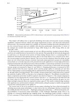
Fig. 14.11. Typical data for recrystallised grain size as a function of prior plastic deformation. Note that,
below a critical deformation, there is not enough strain energy to nucleate the new strain-free grains. This is
just like the critical undercooling needed to nucleate a solid from its liquid (see Fig. 7.4).
boundaries. These boundaries form the surfaces of irregular cells – small volumes
which are relatively free of dislocations. During recovery the dislocation density goes
down only slightly: the hardness and ductility are almost unchanged. The major changes
come from recrystallisation. New grains nucleate and grow (Fig. 14.10d) until the whole
of the metal consists of undeformed grains (Fig. 14.10e). The dislocation density re-
turns to its original value, as do the values of the hardness and ductility.
Recrystallisation is not limited just to getting rid of work-hardening. It is also a
powerful way of controlling the grain size of worked metals. Although single crystals
are desirable for a few specialised applications (see Chapter 9) the metallurgist almost
always seeks a fine grain size. To begin with, fine-grained metals are stronger and
tougher than coarse-grained ones. And large grains can be undesirable for other
reasons. For example, if the grain size of a metal sheet is comparable to the sheet
thickness, the surface will rumple when the sheet is pressed to shape; and this makes
it almost impossible to get a good surface finish on articles such as car-body panels or
spun aluminium saucepans.
The ability to control grain size by recrystallisation is due to the general rule (e.g.
Chapter 11) that the harder you drive a transformation, the finer the structure you get.
In the case of recrystallisation this means that the greater the prior plastic deformation
(and hence the stored strain energy) the finer the recrystallised grain size (Fig. 14.11).
To produce a fine-grained sheet, for example, we simply reduce the thickness by about
50% in a cold rolling operation (to give the large stored strain energy) and then anneal
the sheet in a furnace (to give the fine recrystallised structure).
Machining
Most engineering components require at least some machining: turning, drilling, mill-
ing, shaping, or grinding. The cutting tool (or the abrasive particles of the grinding
154 Engineering Materials 2
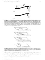
Fig. 14.12. Machining.
wheel) parts the chip from the workpiece by a process of plastic shear (Fig. 14.12).
Thermodynamically, all that is required is the energy of the two new surfaces created
when the chip peels off the surface; in reality, the work done in the plastic shear (a
strain of order 1) greatly exceeds this minimum necessary energy. In addition, the
friction is very high (
µ
≈ 0.5) because the chip surface which bears against the tool
is freshly formed, and free from adsorbed films which could reduce adhesion. This
friction can be reduced by generous lubrication with water-soluble cutting fluids, which
also cool the tool. Free cutting alloys have a built-in lubricant which smears across the
tool face as the chip forms: lead in brass, manganese sulphide in steel.
Machining is expensive – in energy, wasted material and time. Forming routes
which minimise or avoid machining result in considerable economies.
Joining
Many of the processes used to join one metal to another are based on casting. We have
already looked at fusion welding (Fig. 13.6). The most widely used welding process is
arc welding: an electric arc is struck between an electrode of filler metal and the
workpieces, providing the heat needed to melt the filler and fuse it to the parent
plates. The electrode is coated with a flux which melts and forms a protective cover on
the molten metal. In submerged arc welding, used for welding thick sections automatic-
ally, the arc is formed beneath a pool of molten flux. In gas welding the heat source is
an oxyacetylene flame. In spot welding the metal sheets to be joined are pressed to-
gether between thick copper electrodes and fused together locally by a heavy current.
Small, precise welds can be made using either an electron beam or a laser beam as the
heat source.
Production, forming and joining of metals 155
Brazing and soldering are also fine-scale casting processes. But they use filler metals
which melt more easily than the parent metal (see Table 4.1). The filler does not join to
the parent metal by fusion (melting together). Instead, the filler spreads over, or wets,
the solid parent metal and, when it solidifies, becomes firmly stuck to it. True metal-to-
metal contact is essential for good wetting. Before brazing, the parent surfaces are
either mechanically abraded or acid pickled to remove as much of the surface oxide
film as possible. Then a flux is added which chemically reduces any oxide that forms
during the heating cycle. Specialised brazing operations are done in a vacuum furnace
which virtually eliminates oxide formation.
Adhesives, increasingly used in engineering applications, do not necessarily require
the application of heat. A thin film of epoxy, or other polymer, is spread on the
surfaces to be joined, which are then brought together under pressure for long enough
for the adhesive to polymerise or set. Special methods are required with adhesives, but
they offer great potential for design.
Metal parts are also joined by a range of fasteners: rivets, bolts, or tabs. In using
them, the stress concentration at the fastener or its hole must be allowed for: fracture
frequently starts at a fastening point.
Surface engineering
Often it is the properties of a surface which are critical in an engineering application.
Examples are components which must withstand wear; or exhibit low friction; or resist
oxidation or corrosion. Then the desired properties can often be achieved by creating a
thin surface layer with good (but expensive) properties on a section of poorer (but
cheaper) metal, offering great economies of production.
Surface treatments such as carburising or nitriding give hard surface layers, which
give good wear and fatigue resistance. In carburising, a steel component is heated into
the austenite region. Carbon is then diffused into the surface until its concentration
rises to 0.8% or more. Finally the component is quenched into oil, transforming the
surface into hard martensite. Steels for nitriding contain aluminium: when nitrogen
is diffused into the surface it reacts to form aluminium nitride, which hardens the
surface by precipitation hardening. More recently ion implantation has been used: for-
eign ions are accelerated in a strong electric field and are implanted into the surface.
Finally, laser heat treatment has been developed as a powerful method for producing
hard surfaces. Here the surface of the steel is scanned with a laser beam. As the beam
passes over a region of the surface it heats it into the austenite region. When the beam
passes on, the surface it leaves behind is rapidly quenched by the cold metal beneath
to produce martensite.
Energy-efficient forming
Many of the processes used for working metals are energy-intensive. Large amounts
of energy are needed to melt metals, to roll them to sections, to machine them or to
weld them together. Broadly speaking, the more steps there are between raw metal
156 Engineering Materials 2
and finished article (see Fig. 14.1) then the greater is the cost of production. There is
thus a big incentive to minimise the number of processing stages and to maximise the
efficiency of the remaining operations. This is not new. For centuries, lead sheet for
organ pipes has been made in a single-stage casting operation. The Victorians were the
pioneers of pouring intricate iron castings which needed the minimum of machining.
Modern processes which are achieving substantial energy savings include the single-
stage casting of thin wires or ribbons (melt spinning, see Chapter 9) or the spray
deposition of “atomised” liquid metal to give semi-finished seamless tubes. But modi-
fications of conventional processes can give useful economies too. In examining a
production line it is always worth questioning whether a change in processing method
could be introduced with economic benefits.
Background reading
M. F. Ashby and D. R. H. Jones, Engineering Materials I, 2nd edition, Butterworth-Heinemann, 1996.
Further reading
S. Kalpakjian, Manufacturing Processes for Engineering Materials, Addison-Wesley, 1984.
J. A. Schey, Introduction to Manufacturing Processes, McGraw-Hill Kogakusha, 1977.
J. M. Alexander and R. C. Brewer, Manufacturing Properties of Materials, Van Nostrand, 1968.
G. J. Davies, Solidification and Casting, Applied Science Publishers, 1973.
C. R. Calladine, Plasticity for Engineers, Ellis Horwood, 1985.
G. Parrish and G. S. Harper, Production Gas Carburising, Pergamon, 1985.
J. Campbell, Castings, Butterworth-Heinemann, 1991.
Problems
14.1 Estimate the percentage volume contraction due to solidification in pure copper.
Use the following data: T
m
= 1083°C; density of solid copper at 20°C = 8.96 Mg m
–3
;
average coefficient of thermal expansion in the range 20 to 1083°C = 20.6 M K
–1
;
density of liquid copper at T
m
= 8.00 Mg m
–3
.
Answer: 5%.
14.2 A silver replica of a holly leaf is to be made by investment casting. (A natural leaf
is coated with ceramic slurry which is then dried and fired. During firing the leaf
burns away, leaving a mould cavity.) The thickness of the leaf is 0.4 mm. Calcu-
late the liquid head needed to force the molten silver into the mould cavity. It can
be assumed that molten silver does not wet the mould walls.
[Hint: the pressure needed to force a non-wetting liquid into a parallel-sided
cavity of thickness t is given by
p
T
t
(/ )
=
2
Production, forming and joining of metals 157
where T is the surface tension of the liquid.] The density and surface tension of
molten silver are 9.4 Mg m
–3
and 0.90 Nm
–1
.
Answer: 49 mm.
14.3 Aluminium sheet is to be rolled according to the following parameters: starting
thickness 1 mm, reduced thickness 0.8 mm, yield strength 100 MPa. What roll
radius should be chosen to keep the forming pressure below 200 MPa?
Answer: 16.2 mm, or less.
14.4 Aluminium sheet is to be rolled according to the following parameters: sheet
width 300 mm, starting thickness 1 mm, reduced thickness 0.8 mm, yield strength
100 MPa, maximum forming pressure 200 MPa, roll radius 16.2 mm, roll length
300 mm. Calculate the force F that the rolling pressure will exert on each roll.
[Hint: use the average forming pressure, p
av
, shown in Fig. 14.8.]
The design states that the roll must not deflect by more than 0.01 mm at its
centre. To achieve this bending stiffness, each roll is to be backed up by one
secondary roll as shown in Fig. 14.9(b). Calculate the secondary roll radius needed
to meet the specification. The central deflection of the secondary roll is given by
δ
=
5
384
3
FL
EI
where L is the roll length and E is the Young’s modulus of the roll material. I, the
second moment of area of the roll section, is given by
Ir /=
π
s
4
4
where r
s
is the secondary roll radius. The secondary roll is made from steel, with
E = 210 GPa. You may neglect the bending stiffness of the primary roll.
Answers: F = 81 kN; r
s
= 64.5 mm.
14.5 Copper capillary fittings are to be used to solder copper water pipes together as
shown below:
The joint is designed so that the solder layer will yield in shear at the same axial
load F that causes the main tube to fail by tensile yield. Estimate the required
value of W, given the following data: t = 1 mm;
σ
y
(copper) = 120 MPa;
σ
y
(solder)
= 10 MPa.
Answer: 24 mm.
F
w
F
r
†
Solder layer
158 Engineering Materials 2
14.6 A piece of plain carbon steel containing 0.2 wt% carbon was case-carburised to
give a case depth of 0.3 mm. The carburising was done at a temperature of
1000°C. The Fe–C phase diagram shows that, at this temperature, the iron can
dissolve carbon to a maximum concentration of 1.4 wt%. Diffusion of carbon
into the steel will almost immediately raise the level of carbon in the steel to a
constant value of 1.4 wt% just beneath the surface of the steel. However, the
concentration of carbon well below the surface will increase more slowly towards
the maximum value of 1.4 wt% because of the time needed for the carbon to
diffuse into the interior of the steel.
The diffusion of carbon into the steel is described by the time-dependent diffu-
sion equation
Cxt C C
x
Dt
C
s
( , ) ( ) .=− −
+
00
1
2
erf
The symbols have the meanings: C, concentration of carbon at a distance x below
the surface after time t; C
s
, 1.4 wt% C; C
0
, 0.2 wt% C; D, diffusion coefficient for
carbon in steel. The “error function”, erf(y), is given by
erf e d() .yZ
Z
y
=
−
∫
2
2
0
π
The following table gives values for this integral.
y 0 0.1 0.2 0.3 0.4 0.5 0.6 0.7
erf(y) 0 0.11 0.22 0.33 0.43 0.52 0.60 0.68
y 0.8 0.9 1.0 1.1 1.2 1.3 1.4 1.5 ∞
erf(y) 0.74 0.80 0.84 0.88 0.91 0.93 0.95 0.97 1.00
The diffusion coefficient may be taken as
D
RT
exp
=×
−
−−
−
910
125
621
1
m s
kJ mol
where R is the gas constant and T is the absolute temperature.
Calculate the time required for carburisation, if the depth of the case is taken to
be the value of x for which C = 0.5 wt% carbon.
Answer: 8.8 minutes.
Ceramics and glasses 159
B. Ceramics and glasses
160 Engineering Materials 2
Ceramics and glasses 161
Chapter 15
Ceramics and glasses
Introduction
If you have ever dropped a plate on the kitchen floor and seen it disintegrate, you
might question whether ceramics have a role as load-bearing materials in engineering.
But any friend with a historical perspective will enlighten you. Ceramic structures are
larger and have survived longer than any other works. The great pyramid of Giza is
solid ceramic (nearly 1,000,000 tonnes of it); so is the Parthenon, the Forum, the Great
Wall of China. The first cutting tools and weapons were made of flint – a glass; and
pottery from 5000 bc survives to the present day. Ceramics may not be as tough as
metals, but for resistance to corrosion, wear, decay and corruption, they are unsurpassed.
Today, cement and concrete replace stone in most large structures. But cement, too,
is a ceramic: a complicated but fascinating one. The understanding of its structure, and
how it forms, is better now than it used to be, and has led to the development of
special high-strength cement pastes which can compete with polymers and metals in
certain applications.
But the most exciting of all is the development, in the past 20 years, of a range of
high-performance engineering ceramics. They can replace, and greatly improve on,
metals in many very demanding applications. Cutting tools made of sialons or of
dense alumina can cut faster and last longer than the best metal tools. Engineering
ceramics are highly wear-resistant: they are used to clad the leading edges of agri-
cultural machinery like harrows, increasing the life by 10 times. They are inert and
biocompatible, so they are good for making artificial joints (where wear is a big prob-
lem) and other implants. And, because they have high melting points, they can stand
much higher temperatures than metals can: vast development programs in Japan, the
US and Europe aim to put increasing quantities of ceramics into reciprocating engines,
turbines and turbochargers. In the next decade the potential market is estimated at
$1 billion per year. Even the toughness of ceramics has been improved: modern body-
armour is made of plates of boron carbide or of alumina, sewn into a fabric vest.
The next six chapters of this book focus on ceramics and glasses: non-metallic,
inorganic solids. Five classes of materials are of interest to us here:
(a) Glasses, all of them based on silica (SiO
2
), with additions to reduce the melting
point, or give other special properties.
(b) The traditional vitreous ceramics, or clay products, used in vast quantities for plates
and cups, sanitary ware, tiles, bricks, and so forth.
(c) The new high-performance ceramics, now finding application for cutting tools, dies,
engine parts and wear-resistant parts.
162 Engineering Materials 2
(d) Cement and concrete: a complex ceramic with many phases, and one of three essen-
tial bulk materials of civil engineering.
(e) Rocks and minerals, including ice.
As with metals, the number of different ceramics is vast. But there is no need to
remember them all: the generic ceramics listed below (and which you should re-
member) embody the important features; others can be understood in terms of these.
Although their properties differ widely, they all have one feature in common: they
are intrinsically brittle, and it is this that dictates the way in which they can be used.
They are, potentially or actually, cheap. Most ceramics are compounds of oxygen,
carbon or nitrogen with metals like aluminium or silicon; all five are among the most
plentiful and widespread elements in the Earth’s crust. The processing costs may be
high, but the ingredients are almost as cheap as dirt: dirt, after all, is a ceramic.
The generic ceramics and glasses
Glasses
Glasses are used in enormous quantities: the annual tonnage is not far below that of
aluminium. As much as 80% of the surface area of a modern office block can be glass;
and glass is used in a load-bearing capacity in car windows, containers, diving bells
and vacuum equipment. All important glasses are based on silica (SiO
2
). Two are of
primary interest: common window glass, and the temperature-resisting borosilicate
glasses. Table 15.1 gives details.
Table 15.1. Generic glasses
Glass Typical composition (wt%) Typical uses
Soda-lime glass 70 SiO
2
, 10 CaO, 15 Na
2
O Windows, bottles, etc.; easily formed and shaped.
Borosilicate glass 80 SiO
2
, 15 B
2
O
3
, 5 Na
2
O Pyrex; cooking and chemical glassware; high-
temperature strength, low coefficient of
expansion, good thermal shock resistance.
Vitreous ceramics
Potters have been respected members of society since ancient times. Their products
have survived the ravages of time better than any other; the pottery of an era or civilisa-
tion often gives the clearest picture of its state of development and its customs. Mod-
ern pottery, porcelain, tiles, and structural and refractory bricks are made by processes
which, though automated, differ very little from those of 2000 years ago. All are made
from clays, which are formed in the wet, plastic state and then dried and fired. After
firing, they consist of crystalline phases (mostly silicates) held together by a glassy
phase based, as always, on silica (SiO
2
). The glassy phase forms and melts when the
clay is fired, and spreads around the surface of the inert, but strong, crystalline phases,
bonding them together. The important information is summarised in Table 15.2.
Ceramics and glasses 163
Table 15.2. Generic vitreous ceramics
Ceramic Typical composition Typical uses
Porcelain Made from clays: hydrous Electrical insulators.
China alumino-silicate such as Artware and
Pottery Al
2
(Si
2
O
5
)(OH)
4
mixed with other inert tableware tiles.
Brick minerals. Construction; refractory uses.
Table 15.3. Generic high-performance ceramics
Ceramic Typical composition Typical uses
Dense alumina Al
2
O
3
Cutting tools, dies; wear-resistant surfaces, bearings;
Silicon carbide, nitride SiC, Si
3
N
4
medical implants; engine and turbine parts; armour.
Sialons e.g. Si
2
AlON
3
Cubic zirconia ZrO
2
+ 5wt% MgO
Table 15.4. Generic cements and concretes
Cement Typical composition Uses
Portland cement CaO + SiO
2
+ Al
2
O
3
Cast facings, walkways, etc. and as component of concrete.
General construction.
High-performance engineering ceramics
Diamond, of course, is the ultimate engineering ceramic; it has for many years been used
for cutting tools, dies, rock drills, and as an abrasive. But it is expensive. The strength
of a ceramic is largely determined by two characteristics: its toughness (K
IC
), and the
size distribution of microcracks it contains. A new class of fully dense, high-strength
ceramics is now emerging which combine a higher K
IC
with a much narrower distribu-
tion of smaller microcracks, giving properties which make them competitive with
metals, cermets, even with diamond, for cutting tools, dies, implants and engine parts.
And (at least potentially) they are cheap. The most important are listed in Table 15.3.
Cement and concrete
Cement and concrete are used in construction on an enormous scale, equalled only by
structural steel, brick and wood. Cement is a mixture of a combination of lime (CaO),
silica (SiO
2
) and alumina (Al
2
O
3
), which sets when mixed with water. Concrete is sand
and stones (aggregate) held together by a cement. Table 15.4 summarises the most
important facts.
Natural ceramics
Stone is the oldest of all construction materials and the most durable. The pyramids
are 5000 years old; the Parthenon 2200. Stone used in a load-bearing capacity behaves
164 Engineering Materials 2
Table 15.5. Generic natural ceramics
Ceramic Composition Typical uses
Limestone (marble) Largely CaCO
3
5
Sandstone Largely SiO
2
6Building foundations, construction.
Granite Aluminium silicates 7
Ice H
2
O Arctic engineering.
Table 15.6. Ceramic composites
Ceramic composite Components Typical uses
Fibre glass Glass–polymer #High-performance structures.
CFRP Carbon–polymer
$
Cermet Tungsten carbide–cobalt Cutting tools, dies.
Bone Hydroxyapatite–collagen Main structural material of animals.
New ceramic composites Alumina–silicon carbide High temperature and high toughness applications.
Table 15.7. Properties of ceramics
Ceramic Cost Density Young’s Compressive Modulus Weibull
(UK£ (US$) (Mg m
−
3
) modulus strength of rupture exponent
tonne
−
1
) (GPa) (MPa) (MPa) m
Glasses
Soda glass 700 (1000) 2.48 74 1000 50 5
Assume 10
Borosilicate glass 1000 (1400) 2.23 65 1200 55 4
in design
Pottery, etc
.
6
Porcelain 260–1000 2.3–2.5 70 350 45
4
(360–1400)
7
High-performance
engineering
ceramics
Diamond 4 × 10
8
(6 × 10
8
) 3.52 1050 5000 –
Dense alumina Expensive at 3.9 380 3000 300–400 10
Silicon carbide present. 3.2 410 2000 200–500 10
Silicon nitride Potentially 3.2 310 1200 300–850 –
Zirconia 350–1000 5.6 200 2000 200–500 10–21
Sialons (490–1400) 3.2 300 2000 500–830 15
Cement, etc
.
Cement 52 (73) 2.4–2.5 20–30 50 7 12
Concrete 26 (36) 2.4 30–50 50 7 12
Rocks and ice
Limestone Cost of mining 2.7 63 30–80 20 –
Granite and transport 2.6 60–80 65–150 23 –
Ice 0.92 9.1 6 1.7 –
Ceramics and glasses 165
like any other ceramic; and the criteria used in design with stone are the same. One
natural ceramic, however, is unique. Ice forms on the Earth’s surface in enormous
volumes: the Antarctic ice cap, for instance, is up to 3 km thick and almost 3000 km
across; something like 10
13
m
3
of pure ceramic. The mechanical properties are of primary
importance in some major engineering problems, notably ice breaking, and the con-
struction of offshore oil rigs in the Arctic. Table 15.5 lists the important natural ceramics.
Ceramic composites
The great stiffness and hardness of ceramics can sometimes be combined with the
toughness of polymers or metals by making composites. Glass- and carbon-fibre rein-
forced plastics are examples: the glass or carbon fibres stiffen the rather floppy poly-
mer; but if a fibre fails, the crack runs out of the fibre and blunts in the ductile polymer
without propagating across the whole section. Cermets are another example: particles
of hard tungsten carbide bonded by metallic cobalt, much as gravel is bonded with tar
to give a hard-wearing road surface (another ceramic-composite). Bone is a natural
ceramic-composite: particles of hydroxyapatite (the ceramic) bonded together by col-
lagen (a polymer). Synthetic ceramic–ceramic composites (like glass fibres in cement,
or silicon carbide fibres in silicon carbide) are now under development and may have
important high-temperature application in the next decade. The examples are summar-
ised in Table 15.6.
Time Fracture Melting Specific Thermal Thermal Thermal shock
exponent toughness (softening) heat conductivity expansion resistance
n (MPa m
1/2
) temperature (J kg
−
1
K
−
1
) (W m
−
1
K
−
1
) coefficient (K)
(K) (MK
−
1
)
10 0.7 (1000) 990 1 8.5 84
10 0.8 (1100) 800 1 4.0 280
– 1.0 (1400) 800 1 3 220
–– – 510 70 1.2 1000
10 3–5 2323 (1470) 795 25.6 8.5 150
40 – 3110 – 1422 84 4.3 300
40 4 2173 – 627 17 3.2 500
10 4–12 2843 – 670 1.5 8 500
10 5 –– 710 20–25 3.2 510
40 0.2 ––1.8 10–14 #
<50
40 0.2 ––210–14
$
– 0.9 –––8 #
≈100
––– ––8
$
– 0.12 273 (250) –––
166 Engineering Materials 2
Data for ceramics
Ceramics, without exception, are hard, brittle solids. When designing with metals,
failure by plastic collapse and by fatigue are the primary considerations. For ceramics,
plastic collapse and fatigue are seldom problems; it is brittle failure, caused by direct
loading or by thermal stresses, that is the overriding consideration.
Because of this, the data listed in Table 15.7 for ceramic materials differ in emphasis
from those listed for metals. In particular, the Table shows the modulus of rupture (the
maximum surface stress when a beam breaks in bending) and the thermal shock resist-
ance (the ability of the solid to withstand sudden changes in temperature). These,
rather than the yield strength, tend to be the critical properties in any design exercise.
As before, the data presented here are approximate, intended for the first phase of
design. When the choice has narrowed sufficiently, it is important to consult more
exhaustive data compilations (see Further Reading); and then to obtain detailed speci-
fications from the supplier of the material you intend to use. Finally, if the component
is a critical one, you should conduct your own tests. The properties of ceramics are
more variable than those of metals: the same material, from two different suppliers,
could differ in toughness and strength by a factor of two.
There are, of course, many more ceramics available than those listed here: alumina is
available in many densities, silicon carbide in many qualities. As before, the structure-
insensitive properties (density, modulus and melting point) depend little on quality –
they do not vary by more than 10%. But the structure-sensitive properties (fracture
toughness, modulus of rupture and some thermal properties including expansion) are
much more variable. For these, it is essential to consult manufacturers’ data sheets or
conduct your own tests.
Further reading
D. W. Richardson, Modern Ceramic Engineering, Marcel Dekker, 1982.
R. W. Davidge, Mechanical Behaviour of Ceramics, Cambridge University Press, 1979.
W. E. C. Creyke, I. E. J. Sainsbury, and R. Morrell, Design with Non-ductile Materials, Applied
Science, Publishers, 1982.
R. Morrell, Engineering Ceramics – Property Data for the User, HMSO, 1985.
Problems
15.1 What are the five main generic classes of ceramics and glasses? For each generic
class:
(a) give one example of a specific component made from that class;
(b) indicate why that class was selected for the component.
15.2 How do the unique characteristics of ceramics and glasses influence the way in
which these materials are used?
Structure of ceramics 167
Chapter 16
Structure of ceramics
Introduction
A ceramic, like a metal, has structure at the atomic scale: its crystal structure (if it is
crystalline), or its amorphous structure (if it is glassy). It has structure at a larger scale
too: the shape and arrangement of its grains or phases; the size and volume fraction of
pores it contains (most ceramics are porous). Ceramic structures differ from those of
metals. Their intricate details (and they can be pretty intricate) are the province of the
professional ceramist; but you need a working knowledge of their basic features to
understand the processing and the engineering uses of ceramics and to appreciate the
recently developed high-strength ceramics.
Ionic and covalent ceramics
One critical distinction should be drawn right at the beginning. It is that between pre-
dominantly ionic ceramics and those which are predominantly covalent in their bonding.
Ionic ceramics are, typically, compounds of a metal with a non-metal; sodium chlor-
ide, NaCl; magnesium oxide, MgO; alumina Al
2
O
3
; zirconia ZrO
2
. The metal and non-
metal have unlike electric charges: in sodium chloride, for instance, the sodium atoms
have one positive charge and the chlorine atoms have one negative charge each. The
electrostatic attraction between the unlike charges gives most of the bonding. So the
ions pack densely (to get as many plus and minus charges close to each other as
possible), but with the constraint that ions of the same type (and so with the same
charge) must not touch. This leads to certain basic ceramic structures, typified by rock
salt, NaCl, or by alumina Al
2
O
3
, which we will describe later.
Covalent ceramics are different. They are compounds of two non-metals (like silica
SiO
2
), or, occasionally, are just pure elements (like diamond, C, or silicon, Si). An atom
in this class of ceramic bonds by sharing electrons with its neighbours to give a fixed
number of directional bonds. Covalent atoms are a bit like the units of a child’s con-
struction kit which snap together: the position and number of neighbours are rigidly
fixed by the number and position of the connectors on each block. The resulting
structures are quite different from those given by ionic bonding; and as we will see
later, the mechanical properties are different too. The energy is minimised, not by
dense packing, but by forming chains, sheets, or three-dimensional networks. Often these
are non-crystalline; all commercial glasses, for instance, are three-dimensional amorph-
ous networks based on silica, SiO
2
.
We will first examine the simple structures given by ionic and covalent bonding,
and then return to describe the microstructures of ceramics.
168 Engineering Materials 2
Fig. 16.1. Ionic ceramics. (a) The rocksalt, or NaCl, structure. (b) Magnesia, MgO, has the rocksalt
structure. It can be thought of as an f.c.c. packing with Mg ions in the octahedral holes. (c) Cubic zirconia
ZrO
2
: an f.c.c. packing of Zr with O in the tetrahedral holes. (d) Alumina, Al
2
O
3
: a c.p.h. packing of oxygen
with Al in two-thirds of the octahedral holes.
Simple ionic ceramics
The archetype of the ionic ceramic is sodium chloride (“rocksalt”), NaCl, shown in
Fig. 16.1(a). Each sodium atom loses an electron to a chlorine atom; it is the electro-
static attraction between the Na
+
ions and the Cl
−
ions that holds the crystal together.
To achieve the maximum electrostatic interaction, each Na
+
has 6 Cl
−
neighbours and
no Na
+
neighbours (and vice versa); there is no way of arranging single-charged ions
that does better than this. So most of the simple ionic ceramics with the formula AB
have the rocksalt structure.
Magnesia, MgO, is an example (Fig. 16.1b). It is an engineering ceramic, used as a
refractory in furnaces, and its structure is exactly the same as that of rocksalt: the
atoms pack to maximise the density, with the constraint that like ions are not nearest
neighbours.
But there is another way of looking at the structure of MgO, and one which greatly
simplifies the understanding of many of the more complex ceramic structures. Look at
Fig. 16.1(b) again: the oxygen ions (open circles) form an f.c.c. packing. Figure 16.2
shows that the f.c.c. structure contains two sorts of interstitial holes: the larger octahed-
ral holes, of which there is one for each oxygen atom; and the smaller tetrahedral
holes, of which there are two for each oxygen atom. Then the structure of MgO can be
described as a face-centred cubic packing of oxygen with an Mg ion squeezed into each
Structure of ceramics 169
octahedral hole. Each Mg
2+
has six O
2−
as immediate neighbours, and vice versa: the co-
ordination number is 6. The Mg ions wedge the oxygens apart, so that they do not
touch. Then the attraction between the Mg
2+
and the O
2−
ions greatly outweighs the
repulsion between the O
2−
ions, and the solid is very strong and stable (its melting
point is over 2000°C).
This “packing” argument may seem an unnecessary complication. But its advantage
comes now. Consider cubic zirconia, ZrO
2
, an engineering ceramic of growing import-
ance. The structure (Fig. 16.1c) looks hard to describe, but it isn’t. It is simply an f.c.c.
packing of zirconium with the O
2
−
ions in the tetrahedral holes. Since there are two tetrahed-
ral holes for each atom of the f.c.c. structure, the formula works out at ZrO
2
.
Alumina, Al
2
O
3
(Fig. 16.1d), is a structural ceramic used for cutting tools and grind-
ing wheels, and a component in brick and pottery. It has a structure which can be
understood in a similar way. The oxygen ions are close-packed, but this time in the
c.p.h. arrangement, like zinc or titanium. The hexagonal structure (like the f.c.c. one)
has one octahedral hole and two tetrahedral holes per atom. In Al
2
O
3
the Al
3+
ions are
put into the octahedral interstices, so that each is surrounded by six O
2−
ions. But if the
charges are to balance (as they must) there are only enough Al ions to fill two-thirds of
the sites. So one-third of the sites, in an ordered pattern, remain empty. This introduces
a small distortion of the original hexagon, but from our point of view this is unimportant.
There are many other ionic oxides with structures which are more complicated than
these. We will not go into them here. But it is worth knowing that most can be thought
of as a dense (f.c.c. or c.p.h.) packing of oxygen, with various metal ions arranged, in
an orderly fashion, in the octahedral or the tetrahedral holes.
Simple covalent ceramics
The ultimate covalent ceramic is diamond, widely used where wear resistance or very
great strength are needed: the diamond stylus of a pick-up, or the diamond anvils of
an ultra-high pressure press. Its structure, shown in Fig. 16.3(a), shows the 4 co-
ordinated arrangement of the atoms within the cubic unit cell: each atom is at the
centre of a tetrahedron with its four bonds directed to the four corners of the tetra-
hedron. It is not a close-packed structure (atoms in close-packed structures have 12,
not four, neighbours) so its density is low.
The very hard structural ceramics silicon carbide, SiC, and silicon nitride, Si
3
N
4
(used for load-bearing components such as high-temperature bearings and engine
Fig. 16.2. Both the f.c.c. and the c.p.h. structures are close-packed. Both contain one octahedral hole per
atom, and two tetrahedral holes per atom. The holes in the f.c.c. structures are shown here.
170 Engineering Materials 2
Fig. 16.3. Covalent ceramics. (a) The diamond-cubic structure; each atom bonds to four neighbours.
(b) Silicon carbide: the diamond cubic structure with half the atoms replaced by silicon. (c) Cubic silica: the
diamond cubic structure with an SiO
4
tetrahedron on each atom site.
parts) have a structure closely related to that of diamond. If, in the diamond cubic
structure, every second atom is replaced by silicon, we get the sphalerite structure of
SiC, shown in Fig. 16.3(b). Next to diamond, this is one of the hardest of known
substances, as the structural resemblance would suggest.
Silica and silicates
The earth’s crust is largely made of silicates. Of all the raw materials used by man,
silica and its compounds are the most widespread, plentiful and cheap.
Silicon atoms bond strongly with four oxygen atoms to give a tetrahedral unit
(Fig. 16.4a). This stable tetrahedron is the basic unit in all silicates, including that of
pure silica (Fig. 16.3c); note that it is just the diamond cubic structure with every C
atom replaced by an SiO
4
unit. But there are a number of other, quite different, ways in
which the tetrahedra can be linked together.
The way to think of them all is as SiO
4
tetrahedra (or, in polymer terms, monomers)
linked to each other either directly or via a metal ion (M) link. When silica is combined
with metal oxides like MgO, CaO or Al
2
O
3
such that the ratio MO/SiO
2
is 2/1 or
greater, then the resulting silicate is made up of separated SiO
4
monomers (Fig. 16.4a)
linked by the MO molecules. (Olivene, the dominant material in the Earth’s upper
mantle, is a silicate of this type.)
Structure of ceramics 171
Fig. 16.4. Silicate structures. (a) The SiO
4
monomer. (b) The Si
2
O
7
dimer with a bridging oxygen.
(c) A chain silicate. (d) A sheet silicate. Each triangle is the projection of an SiO
4
monomer.
When the ratio MO/SiO
2
is a little less than 2/1, silica dimers form (Fig. 16.4b). One
oxygen is shared between two tetrahedra; it is called a bridging oxygen. This is the first
step in the polymerisation of the monomer to give chains, sheets and networks.
With decreasing amounts of metal oxide, the degree of polymerisation increases.
Chains of linked tetrahedra form, like the long chain polymers with a –C–C– back-
bone, except that here the backbone is an –Si–O–Si–O–Si– chain (Fig. 16.4c). Two
oxygens of each tetrahedron are shared (there are two bridging oxygens). The others
form ionic bonds between chains, joined by the MO. These are weaker than the –Si–
O–Si– bonds which form the backbone, so these silicates are fibrous; asbestos, for
instance, has this structure.
If three oxygens of each tetrahedron are shared, sheet structures form (Fig. 16.4d).
This is the basis of clays and micas. The additional M attaches itself preferentially to
one side of the sheet – the side with the spare oxygens on it. Then the sheet is polarised:
it has a net positive charge on one surface and a negative charge on the other. This
interacts strongly with water, attracting a layer of water between the sheets. This is
what makes clays plastic: the sheets of silicate slide over each other readily, lubricated
172 Engineering Materials 2
by the water layer. As you might expect, sheet silicates are very strong in the plane of
the sheet, but cleave or split easily between the sheets: think of mica and talc.
Pure silica contains no metal ions and every oxygen becomes a bridge between two
silicon atoms giving a three-dimensional network. The high-temperature form, shown in
Fig. 16.3(c), is cubic; the tetrahedra are stacked in the same way as the carbon atoms in
the diamond-cubic structure. At room temperature the stable crystalline form of silica
is more complicated but, as before, it is a three-dimensional network in which all the
oxygens bridge silicons.
Silicate glasses
Commercial glasses are based on silica. They are made of the same SiO
4
tetrahedra on
which the crystalline silicates are based, but they are arranged in a non-crystalline, or
amorphous, way. The difference is shown schematically in Fig. 16.5. In the glass, the
tetrahedra link at the corners to give a random (rather than a periodic) network. Pure
silica forms a glass with a high softening temperature (about 1200°C). Its great strength
and stability, and its low thermal expansion, suit it for certain special applications, but
it is hard to work with because its viscosity is high.
This problem is overcome in commercial glasses by introducing network modifiers to
reduce the viscosity. They are metal oxides, usually Na
2
O and CaO, which add posit-
ive ions to the structure, and break up the network (Fig. 16.5c). Adding one molecule
of Na
2
O, for instance, introduces two Na
+
ions, each of which attaches to an oxygen of
a tetrahedron, making it non-bridging. This reduction in cross-linking softens the glass,
reducing its glass temperature T
g
(the temperature at which the viscosity reaches such a
high value that the glass is a solid). Glance back at the table in Chapter 15 for generic
glasses; common window glass is only 70% SiO
2
: it is heavily modified, and easily
Fig. 16.5. Glass formation. A 3-co-ordinated crystalline network is shown at (a). But the bonding
requirements are still satisfied if a random (or glassy) network forms, as shown at (b). The network
is broken up by adding network modifiers, like Na
2
O, which interrupt the network as shown at (c).
Structure of ceramics 173
Fig. 16.6. A typical ceramic phase diagram: that for alloys of SiO
2
with Al
2
O
3
. The intermediate compound
3Al
2
O
3
SiO
2
is called mullite.
worked at 700°C. Pyrex is 80% SiO
2
; it contains less modifier, has a much better
thermal shock resistance (because its thermal expansion is lower), but is harder to
work, requiring temperatures above 800°C.
Ceramic alloys
Ceramics form alloys with each other, just as metals do. But the reasons for alloying
are quite different: in metals it is usually to increase the yield strength, fatigue strength
or corrosion resistance; in ceramics it is generally to allow sintering to full density, or
to improve the fracture toughness. But for the moment this is irrelevant; the point here
is that one deals with ceramic alloys just as one did with metallic alloys. Molten
oxides, for the most part, have large solubilities for other oxides (that is why they
make good fluxes, dissolving undesirable impurities into a harmless slag). On cooling,
they solidify as one or more phases: solid solutions or new compounds. Just as for
metals, the constitution of a ceramic alloy is described by the appropriate phase diagram.
Take the silica–alumina system as an example. It is convenient to treat the compon-
ents as the two pure oxides SiO
2
and Al
2
O
3
(instead of the three elements Si, Al and
O). Then the phase diagram is particularly simple, as shown in Fig. 16.6. There is a
compound, mullite, with the composition (SiO
2
)
2
(Al
2
O
3
)
3
, which is slightly more stable
than the simple solid solution, so the alloys break up into mixtures of mullite and
alumina, or mullite and silica. The phase diagram has two eutectics, but is otherwise
straightforward.
The phase diagram for MgO and Al
2
O
3
is similar, with a central compound, spinel,
with the composition MgOAl
2
O
3
. That for MgO and SiO
2
, too, is simple, with a com-
pound, forsterite, having the composition (MgO)
2
SiO
2
. Given the composition, the
equilibrium constitution of the alloy is read off the diagram in exactly the way de-
scribed in Chapter 3.
174 Engineering Materials 2
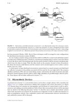
Fig. 16.7. Microstructural features of a crystalline ceramic: grains, grain boundaries, pores, microcracks
and second phases.
The microstructure of ceramics
Crystalline ceramics form polycrystalline microstructures, very like those of metals
(Fig. 16.7). Each grain is a more or less perfect crystal, meeting its neighbours at grain
boundaries. The structure of ceramic grain boundaries is obviously more complicated
than those in metals: ions with the same sign of charge must still avoid each other and,
as far as possible, valency requirements must be met in the boundary, just as they are
within the grains. But none of this is visible at the microstructural level, which for a
pure, dense ceramic, looks just like that of a metal.
Many ceramics are not fully dense. Porosities as high as 20% are a common feature
of the microstructure (Fig. 16.7). The pores weaken the material, though if they are
well rounded, the stress concentration they induce is small. More damaging are cracks;
they are much harder to see, but they are nonetheless present in most ceramics, left by
processing, or nucleated by differences in thermal expansion or modulus between
grains or phases. These, as we shall see in the next chapter, ultimately determine the
strength of the material. Recent developments in ceramic processing aim to reduce the
size and number of these cracks and pores, giving ceramic bodies with tensile strengths
as high as those of high-strength steel (more about that in Chapter 18).
Vitreous ceramics
Pottery and tiles survive from 5000 bc, evidence of their extraordinary corrosion resist-
ance and durability. Vitreous ceramics are today the basis of an enormous industry,
turning out bricks, tiles and white-ware. All are made from clays: sheet silicates such
as the hydrated alumino-silicate kaolin, Al
2
(Si
2
O
5
)(OH)
4
. When wet, the clay draws
water between the silicate sheets (because of its polar layers), making it plastic and
easily worked. It is then dried to the green state, losing its plasticity and acquiring
enough strength to be handled for firing. The firing – at a temperature between 800
Structure of ceramics 175
and 1200°C – drives off the remaining water, and causes the silica to combine with
impurities like CaO to form a liquid glass which wets the remaining solids. On cool-
ing, the glass solidifies (but is still a glass), giving strength to the final composite of
crystalline silicates bonded by vitreous bonds. The amount of glass which forms dur-
ing firing has to be carefully controlled: too little, and the bonding is poor; too much,
and the product slumps, or melts completely.
As fired, vitreous ceramics are usually porous. To seal the surface, a glaze is applied,
and the product refired at a lower temperature than before. The glaze is simply a
powdered glass with a low melting point. It melts completely, flows over the surface
(often producing attractive patterns or textures), and wets the underlying ceramic,
sucking itself into the pores by surface tension. When cold again, the surface is not
only impervious to water, it is also smooth, and free of the holes and cracks which
would lead to easy fracture.
Stone or rock
Sedimentary rocks (like sandstone) have a microstructure rather like that of a vitreous
ceramic. Sandstone is made of particles of silica, bonded together either by more silica
or by calcium carbonate (CaCO
3
). Like pottery, it is porous. The difference lies in the
way the bonding phase formed: it is precipitated from solution in ground water, rather
than formed by melting.
Igneous rocks (like granite) are much more like the SiO
2
–Al
2
O
3
alloys described in
the phase diagram of Fig. 16.6. These rocks have, at some point in their history, been
hot enough to have melted. Their structure can be read from the appropriate phase
diagram: they generally contain several phases and, since they have melted, they are
fully dense (though they still contain cracks nucleated during cooling).
Ceramic composites
Most successful composites combine the stiffness and hardness of a ceramic (like glass,
carbon, or tungsten carbide) with the ductility and toughness of a polymer (like epoxy)
or a metal (like cobalt). You will find all you need to know about them in Chapter 25.
Further reading
W. D. Kingery, H. F. Bowen, and D. R. Uhlman, Introduction to Ceramics, 2nd edition, Wiley, 1976.
I. J. McColm, Ceramic Science for Materials Technologists, Chapman and Hall, 1983.
Problems
16.1 Describe, in a few words, with an example or sketch as appropriate, what is
meant by each of the following:
176 Engineering Materials 2
(a) an ionic ceramic;
(b) a covalent ceramic;
(c) a chain silicate;
(d) a sheet silicate;
(e) a glass;
(f) a network modifier;
(g) the glass temperature;
(h) a vitreous ceramic;
(i) a glaze;
(j) a sedimentary rock;
(k) an igneous rock.
The mechanical properties of ceramics 177
Chapter 17
The mechanical properties of ceramics
Introduction
A Ming vase could, one would hope, perform its primary function – that of pleasing
the eye – without being subjected to much stress. Much glassware, vitreous ceramic
and porcelain fills its role without carrying significant direct load, though it must
withstand thermal shock (if suddenly heated or cooled), and the wear and tear of
normal handling. But others, such as brick, refractories and structural cement, are
deliberately used in a load-bearing capacity; their strength has a major influence on the
design in which they are incorporated. And others still – notably the high-performance
engineering ceramics and abrasives – are used under the most demanding conditions
of stress and temperature.
In this chapter we examine the mechanical properties of ceramics and, particularly,
what is meant by their “strength”.
The elastic moduli
Ceramics, like metals (but unlike polymers) have a well-defined Young’s modulus: the
value does not depend significantly on loading time (or, if the loading is cyclic, on
frequency). Ceramic moduli are generally larger than those of metals, reflecting the
greater stiffness of the ionic bond in simple oxides, and of the covalent bond in silic-
ates. And since ceramics are largely composed of light atoms (oxygen, carbon, silicon,
aluminium) and their structures are often not close-packed, their densities are low.
Because of this their specific moduli (E/
ρ
) are attractively high. Table 17.1 shows that
Table 17.1 Specific moduli: ceramics compared to metals
Material Modulus
E
Density
r
Specific modulus E/
r
(GPa) (Mg m
−
3
) (GPa/Mg m
−
3
)
Steels 210 7.8 27
Al alloys 70 2.7 26
Alumina, Al
2
O
3
390 3.9 100
Silica, SiO
2
69 2.6 27
Cement 45 2.4 19