Engineering Materials Vol II (microstructures_ processing_ design) 2nd ed. - M. Ashby_ D. Jones (1999) WW Part 9 ppsx
Bạn đang xem bản rút gọn của tài liệu. Xem và tải ngay bản đầy đủ của tài liệu tại đây (591.69 KB, 27 trang )
Special topic: cements and concretes 207
Chapter 20
Special topic: cements and concretes
Introduction
Concrete is a particulate composite of stone and sand, held together by an adhesive. The
adhesive is usually a cement paste (used also as an adhesive to join bricks or stones),
but asphalt or even polymers can be used to give special concretes. In this chapter
we examine three cement pastes: the primitive pozzolana; the widespread Portland
cement; and the newer, and somewhat discredited, high-alumina cement. And we con-
sider the properties of the principal cement-based composite, concrete. The chemistry
will be unfamiliar, but it is not difficult. The properties are exactly those expected of a
ceramic containing a high density of flaws.
Chemistry of cements
Cement, of a sort, was known to the ancient Egyptians and Greeks. Their lime-cement
was mixed with volcanic ash by the Romans to give a lime mortar; its success can be
judged by the number of Roman buildings still standing 2000 years later. In countries
which lack a sophisticated manufacturing and distribution system, these pozzolana
cements are widely used (they are named after Pozzuoli, near Naples, where the ash
came from, and which is still subject to alarming volcanic activity). To make them,
chalk is heated at a relatively low temperature in simple wood-fired kilns to give lime
Chalk (CaCO
3
)
Heat
C
→
°600
Lime (CaO). (20.1)
The lime is mixed with water and volcanic ash and used to bond stone, brick, or even
wood. The water reacts with lime, turning it into Ca(OH)
2
; but in doing so, a surface
reaction occurs with the ash (which contains SiO
2
) probably giving a small mount of
(CaO)
3
(SiO
2
)
2
(H
2
O)
3
and forming a strong bond. Only certain volcanic ashes have an
active surface which will bond in this way; but they are widespread enough to be
readily accessible.
The chemistry, obviously, is one of the curses of the study of cement. It is greatly
simplified by the use of a reduced nomenclature. The four ingredients that matter in any
cement are, in this nomenclature
Lime CaO = C
Alumina Al
2
O
3
= A
Silica SiO
2
= S
Water H
2
O = H.
208 Engineering Materials 2
Fig. 20.1. A pozzolana cement. The lime (C) reacts with silica (S) in the ash to give a bonding layer of
tobomorite gel C
3
S
2
H
3
.
The key product, which bonds everything together, is
Tobomorite gel (CaO)
3
(SiO
2
)
2
(H
2
O)
3
= C
3
S
2
H
3
.
In this terminology, pozzolana cement is C mixed with a volcanic ash which has active
S on its surface. The reactions which occur when it sets (Fig. 20.1) are
C + H → CH (in the bulk) (20.2)
and
3C + 2S + 3H → C
3
S
2
H
3
(on the pozzolana surface). (20.3)
The tobomorite gel bonds the hydrated lime (CH) to the pozzolana particles. These
two equations are all you need to know about the chemistry of pozzolana cement.
Those for other cements are only slightly more complicated.
The world’s construction industry thrived on lime cements until 1824, when a Leeds
entrepreneur, Jo Aspdin, took out a patent for “a cement of superior quality, resem-
bling Portland stone” (a white limestone from the island of Portland). This Portland
cement is prepared by firing a controlled mixture of chalk (CaCO
3
) and clay (which is
just S
2
AH
2
) in a kiln at 1500°C (a high temperature, requiring special kiln materials
and fuels, so it is a technology adapted to a developed country). Firing gives three
products
Chalk + Clay
Heat
C
→
°1500
C
3
A + C
2
S + C
3
S. (20.4)
When Portland cement is mixed with water, it hydrates, forming hardened cement
paste (“h.c.p.”). All cements harden by reaction, not by drying; indeed, it is important
to keep them wet until full hardness is reached. Simplified a bit, two groups of reac-
tions take place during the hydration of Portland cement. The first is fast, occurring in
the first 4 hours, and causing the cement to set. It is the hydration of the C
3
A
C
3
A + 6H → C
3
AH
6
+ heat. (20.5)
The second is slower, and causes the cement to harden. It starts after a delay of
10 hours or so, and takes 100 days or more before it is complete. It is the hydration of
C
2
S and C
3
S to tobomorite gel, the main bonding material which occupies 70% of the
structure
Special topic: cements and concretes 209
Fig. 20.2. (a) The hardening of Portland cement. The setting reaction (eqn. 20.5) is followed by the
hardening reactions (eqns 20.6 and 20.7). Each is associated with the evolution of heat (b).
2C
2
S + 4H → C
3
S
2
H
3
+ CH + heat (20.6)
2C
3
S + 6H → C
3
S
2
H
3
+ 3CH + heat. (20.7)
d
Tobomorite gel.
Portland cement is stronger than pozzolana because gel forms in the bulk of the
cement, not merely at its surface with the filler particles. The development of strength
is shown in Fig. 20.2(a). The reactions give off a good deal of heat (Fig. 20.2b). It is
used, in cold countries, to raise the temperature of the cement, preventing the water it
contains from freezing. But in very large structures such as dams, heating is a prob-
lem: then cooling pipes are embedded in the concrete to pump the heat out, and left in
place afterwards as a sort of reinforcement.
High-alumina cement is fundamentally different from Portland cement. As its name
suggests, it consists mainly of CA, with very little C
2
S or C
3
S. Its attraction is its high
hardening rate: it achieves in a day what Portland cement achieves in a month. The
hardening reaction is
CA + 10H → CAH
10
+ heat. (20.8)
But its long-term strength can be a problem. Depending on temperature and environ-
ment, the cement may deteriorate suddenly and without warning by “conversion” of
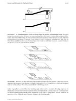
210 Engineering Materials 2
Fig. 20.3. The setting and hardening of Portland cement. At the start (a) cement grains are mixed with
water, H. After 15 minutes (b) the setting reaction gives a weak bond. Real strength comes with the hardening
reaction (c), which takes some days.
the metastable CAH
10
to the more stable C
3
AH
6
(which formed in Portland cement).
There is a substantial decrease in volume, creating porosity and causing drastic loss of
strength. In cold, dry environments the changes are slow, and the effects may not be
evident for years. But warm, wet conditions are disastrous, and strength may be lost in
a few weeks.
The structure of Portland cement
The structure of cement, and the way in which it forms, are really remarkable. The
angular cement powder is mixed with water (Fig. 20.3). Within 15 minutes the setting
reaction (eqn. 20.5) coats the grains with a gelatinous envelope of hydrate (C
3
AH
6
).
The grains are bridged at their point of contact by these coatings, giving a network of
weak bonds which cause a loss of plasticity. The bonds are easily broken by stirring,
but they quickly form again.
Hardening (eqns. 20.6 and 20.7) starts after about 3 hours. The gel coating develops
protuberances which grow into thin, densely packed rods radiating like the spines of
a sea urchin from the individual cement grains. These spines are the C
3
S
2
H
3
of the
second set of reactions. As hydration continues, the spines grow, gradually penetrat-
ing the region between the cement grains. The interlocked network of needles eventu-
ally consolidates into a rigid mass, and has the further property that it grows into, and
binds to, the porous surface of brick, stone or pre-cast concrete.
The mechanism by which the spines grow is fascinating (Fig. 20.4). The initial
envelope of hydrate on the cement grains, which gave setting, also acts as a semi-
Special topic: cements and concretes 211
Fig. 20.4. The mechanism by which the spiney structure of C
3
S
2
H
3
grows.
permeable membrane for water. Water is drawn through the coating because of the
high concentration of calcium inside, and a pressure builds up within the envelope
(the induction period, shown in Fig. 20.2). This pressure bursts through the envelope,
squirting little jets of a very concentrated solution of C
3
S and C
2
S into the surrounding
water. The outer surface of the jet hydrates further to give a tube of C
3
S
2
H
3
. The liquid
within the tube, protected from the surrounding water, is pumped to the end by the
osmotic pressure where it reacts, extending the tube. This osmotic pump continues to
operate, steadily supplying reactants to the tube ends, which continue to grow until all
the water or all the unreacted cement are used up.
Hardening is just another (rather complicated) example of nucleation and growth.
Nucleation requires the formation, and then breakdown, of the hydrate coating; the
“induction period” shown in Fig. 20.2 is the nucleation time. Growth involves the
passage of water by osmosis through the hydrate film and its reaction with the cement
grain inside. The driving force for the transformation is the energy released when C
2
S
and C
3
S react to give tobomorite gel C
3
S
2
H
3
. The rate of the reaction is controlled by
the rate at which water molecules diffuse through the film, and thus depends on
temperature as
rate ∝ exp(–Q/RT). (20.9)
Obviously, too, the rate will depend on the total surface area of cement grains avail-
able for reaction, and thus on the fineness of the powder. So hardening is accelerated
by raising the temperature, and by grinding the powder more finely.
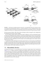
Concrete
Concrete is a mixture of stone and sand (the aggregate), glued together by cement
(Fig. 20.5). The aggregate is dense and strong, so the weak phase is the hardened
cement paste, and this largely determines the strength. Compared with other materials,
cement is cheap; but aggregate is cheaper, so it is normal to pack as much aggregate
into the concrete as possible whilst still retaining workability.
212 Engineering Materials 2
The best way to do this is to grade the aggregate so that it packs well. If particles of
equal size are shaken down, they pack to a relative density of about 60%. The density
is increased if smaller particles are mixed in: they fill the spaces between the bigger
ones. A good combination is a 60–40 mixture of sand and gravel. The denser packing
helps to fill the voids in the concrete, which are bad for obvious reasons: they weaken
it, and they allow water to penetrate (which, if it freezes, will cause cracking).
When concrete hardens, the cement paste shrinks. The gravel, of course, is rigid, so
that small shrinkage cracks are created. It is found that air entrainment (mixing small
bubbles of air into the concrete before pouring) helps prevent the cracks spreading.
The strength of cement and concrete
The strength of Portland cement largely depends on its age and its density. The devel-
opment of strength with time was shown in Fig. 20.2(a): it still increases slowly after a
year. Too much water in the original mixture gives a weak low-density cement (be-
cause of the space occupied by the excess water). Too little water is bad too because
the workability is low and large voids of air get trapped during mixing. A water/
cement ratio of 0.5 is a good compromise, though a ratio of 0.38 actually gives enough
water to allow the reactions to go to completion.
The Young’s modulus of cement paste varies with density as
E
E
ss
=
ρ
ρ
3
(20.10)
where E
s
and
ρ
s
are the modulus and the density of solid tobomorite gel (32 GPa and
2.5 Mg m
−3
). Concrete, of course, contains a great deal of gravel with a modulus three
or so times greater than that of the paste. Its modulus can be calculated by the meth-
ods used for composite materials, giving
E
V
E
V
E
a
a
p
p
concrete
.=+
−1
(20.11)
Here, V
a
and V
p
are the volume fractions of aggregate and cement paste, and E
a
and E
p
are their moduli. As Fig. 20.6 shows, experimental data for typical concretes fit this
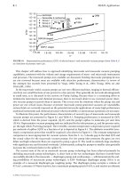
equation well.
Fig. 20.5. Concrete is a particulate composite of aggregate (60% by volume) in a matrix of hardened
cement paste.
Special topic: cements and concretes 213
Fig. 20.6. The modulus of concrete is very close to that given by simple composite theory (eqn. 20.11).
Fig. 20.7. The compressive crushing of a cement or concrete block.
When cement is made, it inevitably contains flaws and cracks. The gel (like all
ceramics) has a low fracture toughness: K
IC
is about 0.3 MPa m
1/2
. In tension it is the
longest crack which propagates, causing failure. The tensile strength of cement and
concrete is around 4 MPa, implying a flaw size of 1 mm or so. The fracture toughness
of concrete is a little higher than that of cement, typically 0.5 MPa m
1/2
. This is because
the crack must move round the aggregate, so the total surface area of the crack is
greater. But this does not mean that the tensile strength is greater. It is difficult to
make the cement penetrate evenly throughout the aggregate, and if it does not, larger
cracks or flaws are left. And shrinkage, mentioned earlier, creates cracks on the same
scale as the largest aggregate particles. The result is that the tensile strength is usually
a little lower than that of carefully prepared cement. These strengths are so low
that engineers, when designing with concrete and cement, arrange that it is always
loaded in compression.
In compression, a single large flaw is not fatal (as it is tension). As explained in
Chapter 17, cracks at an angle to the compression axis propagate in a stable way
(requiring a progressive increase in load to make them propagate further). And they
bend so that they run parallel to the compression axis (Fig. 20.7). The stress–strain
curve therefore rises (Fig. 20.8), and finally reaches a maximum when the density of
214 Engineering Materials 2
cracks is so large that they link to give a general crumbling of the material. In slightly
more detail:
(a) Before loading, the cement or concrete contains cracks due to porosity, incomplete
consolidation, and shrinkage stresses.
(b) At low stresses the material is linear elastic, with modulus given in Table 15.7. But
even at low stresses, new small cracks nucleate at the surfaces between aggregate
and cement.
(c) Above 50% of the ultimate crushing stress, cracks propagate stably, giving a stress–
strain curve that continues to rise.
(d) Above 90% of the maximum stress, some of the cracks become unstable, and
continue to grow at constant load, linking with their neighbours. A failure surface
develops at an angle of 30° to the compression axis. The load passes through a
maximum and then drops – sometimes suddenly, but more usually rather slowly.
A material as complicated as cement shows considerable variation in strength. The
mean crushing strength of 100 mm cubes of concrete is (typically) 50 MPa; but a few of
the cubes fail at 40 MPa and a few survive to 60 MPa. There is a size effect too: 150 mm
cubes have a strength which is lower, by about 10%, than that of 100 mm cubes. This
is exactly what we would expect from Weibull’s treatment of the strength of brittle
solids (Chapter 18). There are, for concrete, additional complexities. But to a first
approximation, design can be based on a median strength of 30 MPa and a Weibull
exponent of 12, provided the mixing and pouring are good. When these are poor, the
exponent falls to about 8.
High-strength cements
The low tensile strength of cement paste is, as we have seen, a result of low fracture
toughness (0.3 MPa m
1/2
) and a distribution of large inherent flaws. The scale of the
flaws can be greatly reduced by four steps:
Fig. 20.8. The stress–strain curve for cement or concrete in compression. Cracking starts at about half the
ultimate strength.
Special topic: cements and concretes 215
(a) Milling the cement to finer powder.
(b) Using the “ideal” water/cement ratio (0.38).
(c) Adding polymeric lubricants (which allow the particles to pack more densely).
(d) Applying pressure during hardening (which squeezes out residual porosity).
The result of doing all four things together is a remarkable material with a porosity of
less than 2% and a tensile strength of up to 90 MPa. It is light (density 2.5 Mg m
−3
) and,
potentially, a cheap competitor in many low-stress applications now filled by polymers.
There are less exotic ways of increasing the strength of cement and concrete. One is
to impregnate it with a polymer, which fills the pores and increases the fracture tough-
ness a little. Another is by fibre reinforcement (Chapter 25). Steel-reinforced concrete is
a sort of fibre-reinforced composite: the reinforcement carries tensile loads and, if
prestressed, keeps the concrete in compression. Cement can be reinforced with fine
steel wire, or with glass fibres. But these refinements, though simple, greatly increase
the cost and mean that they are only viable in special applications. Plain Portland
cement is probably the world’s cheapest and most successful material.
Further reading
J. M. Illston, J. M. Dinwoodie, and A. A. Smith, Concrete, Timber and Metals, Van Nostrand, 1979.
D. D. Double and A. Hellawell, “The solidification of Portland cement”, Scientific American,
237(1), 82(1977).
Problems
20.1 In what way would you expect the setting and hardening reactions in cement
paste to change with temperature? Indicate the practical significance of your result.
20.2 A concrete consists of 60% by volume of limestone aggregate plus 40% by volume
of cement paste. Estimate the Young’s modulus of the concrete, given that E for
limestone is 63 GPa and E for cement paste is 25 GPa.
Answer: 39 GPa.
20.3 Why is the tensile strength of conventional cement only about 4 MPa? How can
the tensile strength of cement be increased by improvements in processing? What
is the maximum value of tensile strength which can be achieved by processing
improvements?
Answer: 90 MPa approximately.
20.4 Make a list, based on your own observations, of selected examples of components
and structures made from cement and concrete. Discuss how the way in which
the materials are used in each example is influenced by the low (and highly
variable) tensile strength of cement and concrete.
216 Engineering Materials 2
Polymers 217
C. Polymers and composites
218 Engineering Materials 2
Polymers 219
Chapter 21
Polymers
Introduction
Where people have, since the industrial revolution, used metals, nature uses polymers.
Almost all biological systems are built of polymers which not only perform mechan-
ical functions (like wood, bone, cartilage, leather) but also contain and regulate chem-
ical reactions (leaf, veins, cells). People use these natural polymers, of course, and have
done so for thousands of years. But it is only in this century that they have learned
how to make polymers of their own. Early efforts (bakelite, celluloid, formaldehyde
plastics) were floppy and not very strong; it is still a characteristic of most simple
synthetic polymers that their stiffness (for a given section) is much less than that of
metal or, indeed, of wood or bone. That is because wood and bone are composites:
they are really made up of stiff fibres or particles, embedded in a matrix of simple
polymer. People have learned how to make composites too: the industries which make
high-performance glass, carbon, or Kevlar-fibre reinforced polymers (GFRP, CFRP,
KFRP) enjoy a faster growth rate (over 10% per year) than almost any other branch of
materials production. These new materials are stiff, strong and light. Though expens-
ive, they are finding increasing use in aerospace, transport and sporting goods. And
there are many opportunities for their wider application in other fields like hiking
equipment, medical goods and even apparently insignificant things like spectacle frames:
world-wide, at least 1,000,000,000 people wear spectacles.
And the new polymers are as exciting as the new composites. By crystallising, or by
cross-linking, or by orienting the chains, new polymers are being made which are as
stiff as aluminium; they will quickly find their way into production. The new process-
ing methods can impart resistance to heat as well as to mechanical deformation, open-
ing up new ranges of application for polymers which have already penetrated heavily
into a market which used to be dominated by metals. No designer can afford to
neglect the opportunities now offered by polymers and composites.
But it is a mistake to imagine that metal components can simply be replaced by
components of these newer materials without rethinking the design. Polymers are less
stiff, less strong and less tough than most metals, so the new component requires
careful redesign. Composites, it is true, are stiff and strong. But they are often very
anisotropic, and because they are bound by polymers, their properties can change
radically with a small change in temperature. Proper design with polymers requires a
good understanding of their properties and where they come from. That is the func-
tion of the next four chapters.
220 Engineering Materials 2
In this chapter we introduce the main engineering polymers. They form the basis
of a number of major industries, among them paints, rubbers, plastics, synthetic
fibres and paper. As with metals and ceramics, there is a bewilderingly large number
of polymers and the number increases every year. So we shall select a number of
“generic” polymers which typify their class; others can be understood in terms of
these. The classes of interest to us here are:
(a) Thermoplastics such as polyethylene, which soften on heating.
(b) Thermosets or resins such as epoxy which harden when two components (a resin
and a hardener) are heated together.
(c) Elastomers or rubbers.
(d) Natural polymers such as cellulose, lignin and protein, which provide the mechan-
ical basis of most plant and animal life.
Although their properties differ widely, all polymers are made up of long molecules
with a covalently bonded backbone of carbon atoms. These long molecules are bonded
together by weak Van der Waals and hydrogen (“secondary”) bonds, or by these plus
covalent cross-links. The melting point of the weak bonds is low, not far from room
temperature. So we use these materials at a high fraction of the melting point of the
weak bonds (though not of the much stronger covalent backbone). Not surprisingly,
they show some of the features of a material near its melting point: they creep, and the
elastic deflection which appears on loading increases with time. This is just one import-
ant way in which polymers differ from metals and ceramics, and it necessitates a
different design approach (Chapter 27).
Most polymers are made from oil; the technology needed to make them from coal is
still poorly developed. But one should not assume that dependence on oil makes the
polymer industry specially vulnerable to oil price or availability. The value-added
when polymers are made from crude oil is large. At 1998 prices, one tonne of oil is
about $150; 1 tonne of polyethylene is about $800. So doubling the price of oil does not
double the price of the polymer. And the energy content of metals is large too: that of
aluminium is nearly twice as great as that of most polymers. So polymers are no more
sensitive to energy prices than are most other commodities, and they are likely to be
with us for a very long time to come.
The generic polymers
Thermoplastics
Polyethylene is the commonest of the thermoplastics. They are often described as
linear polymers, that is the chains are not cross-linked (though they may branch occa-
sionally). That is why they soften if the polymer is heated: the secondary bonds which
bind the molecules to each other melt so that it flows like a viscous liquid, allowing it
to be formed. The molecules in linear polymers have a range of molecular weights,
and they pack together in a variety of configurations. Some, like polystyrene, are
amorphous; others, like polyethylene, are partly crystalline. This range of molecular
weights and packing geometries means that thermoplastics do not have a sharp melting
Polymers 221
point. Instead, their viscosity falls over a range of temperature, like that of an inor-
ganic glass.
Thermoplastics are made by adding together (“polymerising”) sub-units (“monomers”)
to form long chains. Many of them are made of the unit
H
C
H
H
C
R
repeated many times. The radical R may simply be hydrogen (as in polyethylene), or
—CH
3
(polypropylene) or —Cl (polyvinylchloride). A few, like nylon, are more com-
plicated. The generic thermoplastics are listed in Table 21.1. The fibre and film-forming
polymers polyacrylonitrile (ACN) and polyethylene teraphthalate (PET, Terylene,
Dacron, Mylar) are also thermoplastics.
Thermosets or resins
Epoxy, familiar as an adhesive and as the matrix of fibre-glass, is a thermoset
(Table 21.2). Thermosets are made by mixing two components (a resin and a hardener)
which react and harden, either at room temperature or on heating. The resulting
polymer is usually heavily cross-linked, so thermosets are sometimes described as
network polymers. The cross-links form during the polymerisation of the liquid resin
and hardener, so the structure is almost always amorphous. On reheating, the addi-
tional secondary bonds melt, and the modulus of the polymer drops; but the cross-
links prevent true melting or viscous flow so the polymer cannot be hot-worked (it
turns into a rubber). Further heating just causes it to decompose.
The generic thermosets are the epoxies and the polyesters (both widely used as
matrix materials for fibre-reinforced polymers) and the formaldehyde-based plastics
(widely used for moulding and hard surfacing). Other formaldehyde plastics, which now
replace bakelite, are ureaformaldehyde (used for electrical fittings) and melamine-
formaldehyde (used for tableware).
Elastomers
Elastomers or rubbers are almost-linear polymers with occasional cross-links in which,
at room temperature, the secondary bonds have already melted. The cross-links pro-
vide the “memory” of the material so that it returns to its original shape on unloading.
The common rubbers are all based on the single structure
C
H
C
R
A
B
C
D
E
F
H
C
H
H
C
H
n
with the position R occupied by H, CH
3
or Cl. They are listed in Table 21.3.
222 Engineering Materials 2
Natural polymers
The rubber polyisoprene is a natural polymer. So, too, are cellulose and lignin, the
main components of wood and straw, and so are proteins like wool or silk. We use
cellulose in vast quantities as paper and (by treating it with nitric acid) we make
celluloid and cellophane out of it. But the vast surplus of lignin left from wood process-
ing, or available in straw, cannot be processed to give a useful polymer. If it could, it
COOCH
3
Thérmoplastic
Composition
Uses
Polyethylene, PE Tubing, film, bottles, cups, electrical insulation,
packaging.
Table 21.1 Generic thermoplastics
A
B
C
D
E
F
H
C
H
n
Partly crystalline.
Polypropylene, PP Same uses as PE, but lighter, stiffer, more resistant to
sunlight.
A
B
C
D
E
F
H
C
H
n
Partly crystalline.
Polytetrafluoroethylene,
PTFE
Teflon. Good, high-temperature polymer with very low
friction and adhesion characteristics. Non-stick
saucepans, bearings, seals.
A
B
C
D
E
F
F
C
F
n
Partly crystalline.
Polystyrene, PS Cheap moulded objects. Toughened with butadiene to
make high-impact polystyrene (HIPS). Foamed with
CO
2
to make common packaging.
A
B
C
D
E
F
H
C
H
n
Amorphous.
Polyvinylchloride, PVC Architectural uses (window frames, etc.). Plasticised to
make artificial leather, hoses, clothing.
A
B
C
D
E
F
H
C
H
n
Amorphous.
Polymethylmethacrylate,
PMMA
Perspex, lucite. Transparent sheet and mouldings.
Aircraft windows, laminated windscreens.
A
B
C
D
E
F
H
C
H
n
Amorphous.
Nylon 66 Textiles, rope, mouldings.
Partly crystalline when
drawn.
H
C
CH
3
H
C
C
6
H
5
H
C
Cl
CH
3
C
C
6
H
11
NO()
n
Polymers 223
Elastomer
Composition
Uses
Polyisoprene Natural rubber.
Table 21.3 Generic elastomers (rubbers)
Amorphous except at high strains.
Polybutadiene Synthetic rubber, car tyres.
Amorphous except at high strains.
Polychloroprene
Neoprene. An oil-resistant rubber used for seals.
Amorphous except at high strains.
A
B
C
D
E
F
H
C
H
n
C C C
CH
3
H
H
H
A
B
C
D
E
F
H
C
H
n
C C C
H
H
H
H
A
B
C
D
E
F
H
C
H
n
C C C
Cl
H
H
H
Thermoset
Composition
Uses
Epoxy Fibreglass, adhesives.
Expensive.
Table 21.2 Generic thermosets or resins
A
B
C
D
E
F
CH
3
C
CH
3
n
C
6
H
4
O C
6
H
4
O CH
2
CH
OH
CH
2
Amorphous.
Polyester Fibreglass, laminates.
Cheaper than epoxy.
A
B
C
D
E
F
Amorphous.
Phenol-formaldehyde Bakelite, Tufnol, Formica.
Rather brittle.
C
6
H
2
A
B
C
D
E
F
OH
CH
2
n
CH
2
Amorphous.
CH
2
OH
C
CH
2
OH
n
(CH
2
)
m
C O
O O
C
224 Engineering Materials 2
)
n
Natural polymer
Composition
Uses
Cellulose Framework of all plant life, as the main structural
component in cell walls.
Table 21.4 Generic natural polymers
Amorphous.Lignin The other main component in cell walls of all plant life.
Protein
Crystalline
(
C
6
H
9
O
6
Gelatin, wool, silk.
A
B
C
D
E
F
n
NH
C
C
H O
R
R is a radical.
Partly crystalline.
Table 21.5 Properties of polymers
Polymer Cost (UK£ Density Young’s Tensile
($US) tonne
−
1
) (Mg m
−
3
) modulus strength
(20°C 100 s) (MPa)
(GPa)
Thermoplastics
Polyethylene, PE (low density) 560 (780) 0.91–0.94 0.15–0.24 7–17
Polyethylene, PE (high density) 510 (700) 0.95–0.98 0.55–1.0 20–37
Polypropylene, PP 675 (950) 0.91 1.2–1.7 50–70
Polytetrafluoroethylene, PTFE – 2.2 0.35 17–28
Polystyrene, PS 650 (910) 1.1 3.0–3.3 35–68
Polyvinyl chloride, PVC (unplasticised) 425 (595) 1.4 2.4–3.0 40–60
Polymethylmethacrylate, PMMA 1070 (1550) 1.2 3.3 80–90
Nylons 2350 (3300) 1.15 2–3.5 60–110
Resins or thermosets
Epoxies 1150 (1600) 1.2–1.4 2.1–5.5 40–85
Polyesters 930 (1300) 1.1–1.4 1.3–4.5 45–85
Phenolformaldehyde 750 (1050) 1.27 8 35–55
Elastomers (rubbers)
Polyisoprene 610 (850) 0.91 0.002–0.1 ≈10
Polybutadiene 610 (850) 1.5 0.004–0.1
Polychloroprene 1460 (2050) 0.94 ≈0.01
Natural polymers
Cellulose fibres 1.5 25–40 ≈1000
Lignin 1.4 2.0 –
Protein 1.2–1.4 ––
Polymers 225
would form the base for a vast new industry. The natural polymers are not as complic-
ated as you might expect. They are listed in Table 21.4.
Material data
Data for the properties of the generic polymers are shown in Table 21.5. But you have
to be particularly careful in selecting and using data for the properties of polymers.
Specifications for metals and alloys are defined fairly tightly; two pieces of Type 316L
stainless steel from two different manufacturers will not differ much. Not so with
polymers: polyethylene made by one manufacturer may be very different from
polyethylene made by another. It is partly because all polymers contain a spectrum of
molecular lengths; slight changes in processing change this spectrum. But it is also
because details of the polymerisation change the extent of molecular branching and
the degree of crystallinity in the final product; and the properties can be further changed
by mechanical processing (which can, in varying degrees, align the molecules) and by
proprietary additives. For all these reasons, data from compilations (like Table 21.5), or
data books, are at best approximate. For accurate data you must use the manufacturers’
data sheets, or conduct your own tests.
Fracture Glass Softening Specific heat Thermal Thermal
toughness temperature expansion (J kg
−
1
K
−
1
) conductivity coefficient
(20°C)
T
g
(K) temperature (W m
−
1
K
−
1
)(MK
−
1
)
(MPa m
1/2
)
T
s
(K)
1–2 270 355 2250 0.35 160–190
2–5 300 390 2100 0.52 150–300
3.5 253 310 1900 0.2 100–300
–– 395 1050 0.25 70–100
2 370 370 1350–1500 0.1–0.15 70–100
2.4 350 370 – 0.15 50–70
1.6 378 400 1500 0.2 54–72
3–5 340 350–420 1900 0.2–0.25 80–95
0.6–1.0 380 400–440 1700–2000 0.2–0.5 55–90
0.5 340 420–440 1200–2400 0.2–0.24 50–100
–– 370–550 1500–1700 0.12–0.24 26–60
– 220 ≈350 ≈2500 ≈0.15 ≈600
– 171 ≈350 ≈2500 ≈0.15 ≈600
– 200 ≈350 ≈2500 ≈0.15 ≈600
–– – – – –
–– – – – –
–– – – – –
226 Engineering Materials 2
There are other ways in which polymer data differ from those for metals or ceram-
ics. Polymers are held together by two sorts of bonds: strong covalent bonds which
form the long chain backbone, and weak secondary bonds which stick the long chains
together. At the glass temperature T
g
, which is always near room temperature, the
secondary bonds melt, leaving only the covalent bonds. The moduli of polymers re-
flect this. Below T
g
most polymers have a modulus of around 3 GPa. (If the polymer is
drawn to fibres or sheet, the molecules are aligned by the drawing process, and the
modulus in the draw-direction can be larger.) But even if T
room
is below T
g
, T
room
will
still be a large fraction of T
g
. Under load, the secondary bonds creep, and the modulus
falls*. The table lists moduli for a loading time of 100 s at room temperature (20°C);
for loading times of 1000 hours, the modulus can fall to one-third of that for the short
(100 s) test. And above T
g
, the secondary bonds melt completely: linear polymers
become very viscous liquids, and cross-linked polymers become rubbers. Then the
modulus can fall dramatically, from 3 GPa to 3 MPa or less.
You can see that design with polymers involves considerations which may differ
from those for design with metals or ceramics. And there are other differences. One of
the most important is that the yield or tensile strength of a polymer is a large fraction
of its modulus; typically,
σ
y
= E/20. This means that design based on general yield
(plastic design) gives large elastic deflections, much larger than in metals and ceramics.
The excessive “give” of a poorly designed polymer component is a common experi-
ence, although it is often an advantage to have deflections without damage – as in
polyethylene bottles, tough plastic luggage, or car bumpers.
The nearness of T
g
to room temperature has other consequences. Near T
g
most
polymers are fairly tough, but K
IC
can drop steeply as the temperature is reduced.
(The early use of polymers for shelving in refrigerators resulted in frequent fractures
at +4°C. These were not anticipated because the polymer was ductile and tough at
room temperature.)
The specific heats of polymers are large – typically 5 times more than those of metals
when measured per kg. When measured per m
3
, however, they are about the same
because of the large differences in density. The coefficients of thermal expansion of
polymers are enormous, 10 to 100 times larger than those of metals. This can lead to
problems of thermal stress when polymers and metals are joined. And the thermal
conductivities are small, 100 to 1000 times smaller than those of metals. This makes
polymers attractive for thermal insulation, particularly when foamed.
In summary, then, design with polymers requires special attention to time-dependent
effects, large elastic deformation and the effects of temperature, even close to room tem-
perature. Room temperature data for the generic polymers are presented in Table 21.5.
As emphasised already, they are approximate, suitable only for the first step of the
design project. For the next step you should consult books (see Further reading), and
when the choice has narrowed to one or a few candidates, data for them should be
sought from manufacturers’ data sheets, or from your own tests. Many polymers
contain additives – plasticisers, fillers, colourants – which change the mechanical prop-
erties. Manufacturers will identify the polymers they sell, but will rarely disclose their
* Remember that the modulus E =
σ
/
ε
.
ε
will increase during creep at constant
σ
. This will give a lower
apparent value of E. Long tests give large creep strains and even lower apparent moduli.
Polymers 227
additives. So it is essential, in making a final choice of material, that both the polymer
and its source are identified and data for that polymer, from that source, are used in the
design calculations.
Further reading
F. W. Billmeyer, Textbook of Polymer Science, 3rd edition, Wiley Interscience, 1984.
J. A. Brydson, Plastics Materials, 6th edition, Butterworth-Heinemann, 1996.
C. Hall, Polymer Materials, Macmillan, 1981.
International Saechtling, Plastics Handbook, Hanser, 1983.
R. M. Ogorkiewicz (ed.), Thermoplastics: Properties and Design, Wiley, 1974.
R. M. Ogorkiewicz, Engineering Design Guide No. 17: The Engineering Properties of Plastics,
Oxford University Press, 1977.
Problems
21.1 What are the four main generic classes of polymers? For each generic class:
(a) give one example of a specific component made from that class;
(b) indicate why that class was selected for the component.
21.2 How do the unique characteristics of polymers influence the way in which these
materials are used?
228 Engineering Materials 2
Chapter 22
The structure of polymers
Introduction
If the architecture of metal crystals is thought of as classical, then that of polymers is
baroque. The metal crystal is infused with order, as regular and symmetrical as the
Parthenon; polymer structures are as exotic and convoluted as an Austrian altarpiece.
Some polymers, it is true, form crystals, but the molecular packing in these crystals is
more like that of the woven threads in a horse blanket than like the neat stacking of
spheres in a metal crystal. Most are amorphous, and then the long molecules twine
around each other like a bag full of tangled rope. And even the polymers which can
crystallise are, in the bulk form in which engineers use them, only partly crystalline:
segments of the molecules are woven into little crystallites, but other segments form a
hopeless amorphous tangle in between.
The simpler polymers (like polyethylene, PMMA and polystyrene) are linear: the
chains, if straightened out, would look like a piece of string. These are the thermoplastics:
if heated, the strings slither past each other and the polymer softens and melts. And, at
least in principle, these polymers can be drawn in such a way that the flow orients the
strings, converting the amorphous tangle into sheet or fibre in which the molecules are
more or less aligned. Then the properties are much changed: if you pull on the fibre
(for example) you now stretch the molecular strings instead of merely unravelling
them, and the stiffness and strength you measure are much larger than before.
The less simple polymers (like the epoxies, the polyesters and the formaldehyde-
based resins) are networks: each chain is cross-linked in many places to other chains,
so that, if stretched out, the array would look like a piece of Belgian lace, somehow
woven in three dimensions. These are the thermosets: if heated, the structure softens
but it does not melt; the cross-links prevent viscous flow. Thermosets are usually a
bit stiffer than amorphous thermoplastics because of the cross-links, but they cannot
easily be crystallised or oriented, so there is less scope for changing their properties by
processing.
In this chapter we review, briefly, the essential features of polymer structures. They
are more complicated than those of metal crystals, and there is no formal framework
(like that of crystallography) in which to describe them exactly. But a looser, less
precise description is possible, and is of enormous value in understanding the propert-
ies that polymers exhibit.
Molecular length and degree of polymerisation
Ethylene, C
2
H
4
, is a molecule. We can represent it as shown in Fig. 22.1(a), where the
square box is a carbon atom, and the small circles are hydrogen. Polymerisation breaks
The structure of polymers 229
the double bond, activating the ethylene monomer (Fig. 22.1b), and allowing it to link
to others, forming a long chain or macromolecule (Fig. 22.1c). The ends of the chain are
a problem: they either link to other macromolecules, or end with a terminator (such as
an —OH group), shown as a round blob.
If only two or three molecules link, we have created a polymer. But to create a solid
with useful mechanical properties, the chains must be longer – at least 500 monomers
long. They are called high polymers (to distinguish them from the short ones) and,
obviously, their length, or total molecular weight, is an important feature of their
structure. It is usual to speak of the degree of polymerisation or DP: the number of
monomer units in a molecule. Commercial polymers have a DP in the range 10
3
to 10
5
.
The molecular weight of a polymer is simply the DP times the molecular weight of
the monomer. Ethylene, C
2
H
4
, for example, has a molecular weight of 28. If the DP for
a batch of polyethylene is 10
4
, then the molecules have an average molecular weight of
280,000. The word “average” is significant. In all commercial polymers there is a range
of DP, and thus of molecular lengths (Fig. 22.2a). Then the average is simply
DP DP (DP)d(DP) =
∞
Ύ
0
P
(22.1)
where P(DP)d(DP) is the fraction of molecules with DP values between DP and DP +
d(DP). The molecular weight is just mDP where m is the molecular weight of the
monomer.
Most polymer properties depend on the average DP. Figure 22.2(b, c), for poly-
ethylene, shows two: the tensile strength, and the softening temperature.
DPs
of less
than 300 give no strength because the short molecules slide apart too easily. The
strength rises with
DP
, but so does the viscosity; it is hard to mould polyethylene if
Fig. 22.1. (a) The ethylene molecule or monomer; (b) the monomer in the activated state, ready to
polymerise with others; (c)–(f) the ethylene polymer (“polyethylene”); the chain length is limited by the
addition of terminators like —OH. The DP is the number of monomer units in the chain.
230 Engineering Materials 2
Fig. 22.2. (a) Linear polymers are made of chains with a spectrum of lengths, or DPs. The probability of a
given DP is
P
(DP); (b) and (c) the strength, the softening temperature and many other properties depend on
the average DP.
the
DP
is much above 10
3
. The important point is that a material like polyethylene
does not have a unique set of properties. There are many polyethylenes; the properties
of a given batch depend on (among other things) the molecular length or
DP
.
The molecular architecture
Thermoplastics are the largest class of engineering polymer. They have linear molecules:
they are not cross-linked, and for that reason they soften when heated, allowing them
to be formed (ways of doing this are described in Chapter 24). Monomers which form
linear chains have two active bonds (they are bifunctional). A molecule with only one
active bond can act as a chain terminator, but it cannot form a link in a chain. Monomers
with three or more active sites (polyfunctional monomers) form networks: they are the
basis of thermosetting polymers, or resins.
The simplest linear-chain polymer is polyethylene (Fig. 22.3a). By replacing one H
atom of the monomer by a side-group or radical R (sausages on Fig. 22.3b, c, d) we
obtain the vinyl group of polymers: R = Cl gives polyvinyl chloride; R = CH
3
gives
The structure of polymers 231
Fig. 22.3. (a) Linear polyethylene; (b) an isotactic linear polymer: the side-groups are all on the same side;
(c) a sindiotactic linear polymer: the side-groups alternate regularly; (d) an atactic linear polymer: the side-
groups alternate irregularly.
polypropylene; R = C
6
H
5
gives polystyrene. The radical gives asymmetry to the
monomer unit, and there is then more than one way in which the unit can be attached
to form a chain. Three arrangements are shown in Fig. 22.3. If all the side-groups are
on the same side, the molecule is called isotactic. If they alternate in some regular way
round the chain it is called sindiotactic. If they alternate randomly it is called atactic.
These distinctions may seem like splitting hairs (protein, another linear polymer),
but they are important: the tacticity influences properties. The regular molecules
(Figs 22.3a,b,c) can stack side-by-side to form crystals: the regularly spaced side-groups
nestle into the regular concavities of the next molecule. The irregular, atactic, molecules
cannot: their side-groups clash, and the molecules are forced into lower-density, non-
crystalline arrangements. Even the type of symmetry of the regular molecules matters:
the isotactic (one-sided) molecules carry a net electric dipole and can be electroactive
(showing piezoelectric effects, for instance), and others cannot.
Some polymerisation processes (such as the Ziegler process for making polyethylene)
are delicate and precise in their operation: they produce only linear chains, and with a
narrow spread of lengths. Others (like the older, high-pressure, ICI process) are crude
and violent: side-groups may be torn from a part-formed molecule, and other growing
molecules may attach themselves there, giving branching. Branching hinders crystallisa-
tion, just as atacticity does. Low-density polyethylene is branched, and for that reason
has a low fraction of crystal (≈50%), a low density, and low softening temperature
(75°C). High-density PE is not branched: it is largely crystalline (≈80%), it is 5% denser,
and it softens at a temperature which is 30°C higher.
The next simplest group of linear polymers is the vinylidene group. Now two of the
hydrogens of ethylene are replaced by radicals. Polymethylmethacrylate (alias PMMA,