Frontiers in Robotics, Automation and Control Part 1 doc
Bạn đang xem bản rút gọn của tài liệu. Xem và tải ngay bản đầy đủ của tài liệu tại đây (1.54 MB, 30 trang )
Frontiers in
Robotics, Automation and Control
Frontiers in
Robotics, Automation and Control
Edited by
Alexander Zemliak
In-Tech
IV
Published by In-Tech
Abstracting and non-profit use of the material is permitted with credit to the source. Statements and
opinions expressed in the chapters are these of the individual contributors and not necessarily those of
the editors or publisher. No responsibility is accepted for the accuracy of information contained in the
published articles. Publisher assumes no responsibility liability for any damage or injury to persons or
property arising out of the use of any materials, instructions, methods or ideas contained inside. After
this work has been published by the In-Teh, authors have the right to republish it, in whole or part, in
any publication of which they are an author or editor, and the make other personal use of the work.
© 2008 In-tech
Additional copies can be obtained from:
First published October 2008
Printed in Croatia
A catalogue record for this book is available from the University Library Rijeka under no. 120101002
Frontiers in Robotics, Automation and Control, Edited by Alexander Zemliak
p. cm.
ISBN 978-953-7619-17-6
1. Robotics. 2. Automation I. Alexander Zemliak
V
Preface
This book contains some new results in automation, control and robotics as well as new
mathematical methods and computational techniques relating to the control theory applica-
tion in physics and mechanical engineering. It contains the latest developments and reflects
the experience of many researchers working in different environments (universities, re-
search centers or even industries), publishing new theories and solving new problems in
various branches of automation, control, robotics and adjacent areas. The main objective of
the book is the interconnection of diverse scientific fields, the cultivation of possible scien-
tific collaboration, the exchange of views and the promotion of new research targets as well
as the future dissemination and diffusion of the scientific knowledge.
This book includes 23 chapters introducing basic research, advanced developments and
applications. The book covers topics such us modeling and practical realization of robotic
control for different applications, researching of the problems of stability and robustness,
automation in algorithm and program developments with application in speech signal proc-
essing and linguistic research, system’s applied control, computations, and control theory
application in mechanics and electronics.
The authors and editor of this book hope that the efforts of the authors to provide high-
level contributions will be appreciated by the relevant scientific and engineering commu-
nity. We are convinced that the book will be a source of knowledge and inspiration for stu-
dents, academic members, researchers and practitioners working on the topics covered by
the book. We cordially thank I-Tech Education and Publishing for their efforts to maintain a
high quality book.
Editor
Alexander Zemliak
Puebla Autonomous University
Mexico
National Technical University of Ukraine “KPI”
Ukraine
VII
Contents
Preface
V
1.
Evaluation of Robotic Force Control Strategies using an Open Architecture
Test Facility
001
Michael Short
2.
Towards a Roadmap for Effective Handset Network Test Automation
017
Clauirton A. Siebra, Andre L. M. Santos and Fabio Q. B. Silva
3.
Automatic Speaker Recognition by Speech Signal
041
Milan Sigmund
4.
Verification Based Model Localizes Faults from Procedural Programs
055
Safeeullah Soomro
5.
Neural Networks Applied to Thermal Damage Classification in
Grinding Process
071
Marcelo M. Spadotto, Paulo Roberto de Aguiar, Carlos C. P. Sousa and
Eduardo C. Bianchi
6.
Motivation in Embodied Intelligence
083
Janusz A. Starzyk
7.
Robot Control by Fuzzy Logic
111
Viorel Stoian and Mircea Ivanescu
8.
Robust Underdetermined Algorithm Using Heuristic-Based Gaussian
Mixture Model for Blind Source Separation
133
Tsung-Ying Sun, Chan-Cheng Liu, Tsung-Ying Tsai, Yu-Peng Jheng and
Jyun-Hong Jheng
9.
Pattern-driven Reuse of Behavioral Specifications in Embedded Control
System Design
151
Miroslav Švéda, Ondřej Ryšavý and Radimir Vrba
10.
Optical Speed Measurement and applications
165
Tibor Takács, Viktor Kálmán and dr. László Vajta
11.
Automatic Construction of a Knowledge System Using Text Data
on the Internet
189
Junichi Takeno, Satoru. Ikemasu and Yukihiro Kato
VIII
12.
Adaptive GPC Structures for Temperature and Relative Humidity
Control of a Nonlinear Passive Air Conditioning Unit
201
Rousseau Tawegoum, Riad Riadi, Ahmed Rachid and Gérard Chasseriaux
13.
Development of a Human-Friendly Omni-directional Wheelchair with
Safety, Comfort and Operability Using a Smart Interface
221
Kazuhiko Terashima, Juan Urbano, Hideo Kitagawa and Takanori Miyoshi
14.
Modeling of a Thirteen-link 3D Biped and Planning of a Walking
Optimal Cyclic Gait using Newton-Euler Formulation
271
David Tlalolini, Yannick Aoustin and Christine Chevallereau
15.
Robust Position Estimation of an Autonomous Mobile Robot
293
Touati Youcef, Amirat Yacine, Djamaa Zaheer and Ali-Chérif Arab
16.
A semantic Inference Method of Unknown Words using Thesaurus
based on an Association Mechanism
319
Seiji Tsuchiya, Hirokazu Watabe, Tsukasa Kawaoka and Fuji Ren
17.
Homography-Based Control of Nonholonomic Mobile Robots:
a Digital Approach
327
Andrea Usai and Paolo Di Giamberardino
18.
Fault Detection with Bayesian Network
341
Verron Sylvain, Tiplica Teodor and Kobi Abdessamad
19.
A Hierarchical Bayesian Hidden Markov Model for
Multi-Dimensional Discrete Data
357
Shigeru Motoi, Yohei Nakada, Toshie Misu, Tomohiro Yazaki,
Takashi Matsumoto and Nobuyuki Yagi
20.
Development of Rough Terrain Mobile Robot using Connected Crawler
-Derivation of sub-optimal number of crawler stages-
375
Sho Yokota, Yasuhiro Ohyama, Hiroshi Hashimoto, Jin-Hua She,
Hisato Kobayashi and Pierre Blazevic
21.
Automatic Generation of Appropriate Greeting Sentences using
Association System
391
Eriko Yoshimura, Seiji Tsuchiya, Hirokazu Watabe and Tsukasa Kawaoka
22.
Extending AI Planning to Solve more Realistic Problems
401
Joseph Zalaket
23.
Network Optimization as a Controllable Dynamic Process
423
Alexander Zemliak
1
Evaluation of Robotic Force Control Strategies
using an Open Architecture Test Facility
Michael Short
University of Leicester
United Kingdom
1. Introduction
Industrial robots are currently employed in a large number of applications and are available
with a wide range of configurations, drive systems, physical sizes and payloads. However,
the numbers in service throughout the world are much less than predicted over twenty
years ago (Engelberger 1980). This is despite major technological advances in related areas
of computing and electronics, and the availability of fast, reliable and low-cost
microprocessors and memory. This situation is mainly a result of historical and economic
circumstances, rather than technical considerations. Industrial robots have traditionally
performed a narrow but well-defined range of tasks to a specified degree of accuracy and
whilst new robot arm designs are specified for many years of continuous operation, the
technological development of their controllers has been slow in comparison with other
computer-based systems.
Traditionally, most industrial robots are designed to allow accurate and repeatable control
of the position and velocity of the tooling at the device’s end effector. Increasingly, these
systems are often also required to perform complex tasks requiring robust and stable force
control strategies. In addition, task constraints sometimes require position or velocity
control in some Degrees-Of-Freedom (DOF), and force control in others. Thus, to fulfil these
extra demands, an important area of robotics research is the implementation of stable and
accurate force control. However this is often difficult to achieve in practice, due to the
technological limitations of current controllers, coupled with the demanding requirements
placed upon them by the advanced control schemes that are needed in cases where robots
are operating in unpredictable or disordered environments.
This chapter describes a research project that has been undertaken to partly address these
issues, by investigating algorithms and controller architectures for the implementation of
stable robotic force control. The chapter is organised as follows. In Section 2, the
fundamental concepts of robotic force control are introduced, and the problems inherent in
the design of stable, robust controllers are described. This Section also describes some of the
difficulties that are faced by developers when implementing force control strategies using
traditional robot controllers. It is shown that linear, fixed-gain feedback controllers designed
using conventional techniques can only provide adequate performance when they are tuned
to specific task requirements. In practice the environmental stiffness at the robot/task
Frontiers in Robotics, Automation and Control
2
interface may be unknown and bounded, and may even vary significantly during the course
of a specific task. In such cases, performance can be significantly degraded and is often
exacerbated further by the sampling and processing limitations of traditional robot
controllers.
In Section 3, a brief summary of previous work in the area of force control is given. Several
strategies designed to help ameliorate the stability problems described in Section 2 are
covered; two of these novel force control strategies are then discussed in greater depth. The
first of these two techniques is based around an adaptive PD controller implemented using
fuzzy inference techniques. The second technique centres on a model-following force
controller that is robust to bounded uncertainty in the environmental stiffness. General
design principles for both types of controller are discussed; the remainder of the chapter
seeks to further investigate the performance of these two strategies. Section 4 describes a
prototype open architecture robot controller that has been developed to overcome some of
the fundamental restrictions of traditional controllers; this facility allows the direct real-time
implementation of the force controllers.
Section 5 provides comparative results from a series of experiments that were undertaken to
evaluate the performance of the controllers. Several additional measures of real-time
performance and design complexity are also discussed. In Section 6, it is concluded that
although both controllers display comparable performance, the model-based controller is
favourable due to its reduced implementation overheads and reduced design effort, coupled
with the fact that it lends itself to a simpler stability analysis.
2. Robotic Force Control
A typical conventional force control scheme is shown in Figure 1 (Zhang & Hemami 1997;
Whitney 1985; Bicker et al. 1994). In the figure, f
r
is the reference force, f
m
is the measured
(processed) force, f
e
is the force feedback error and f
a
is the actual applied force. The
‘Position Controlled Robot’ block consists of a robot and its host (proprietary) controller.
The force sensor and related control elements are typically implemented as a physically
separate system from the host controller. A control signal u is generated by the force
controller, and effectively passed to the host controller as a vector of reference positions to
be tracked. The end effector generates the forces and torques through interaction with the
current contact dynamics. When implementing such a strategy, it is common for the external
outer loop controller to pass the position commands to the proprietary joint controller over
some form of communications link; such a feature has been common in most industrial
robot controllers for many years. For example the ALTER command with the PUMA range
of robots allows position setpoints to be sent from an external device over an RS-232 serial
link, using a simple messaging protocol (Bicker et al. 1994).
The contact dynamics are represented by the combined stiffness at the end effector/task
interface in the direction of the applied force (K
e
). There is quite often a very short lag in
these dynamics; however this is often neglected as it is many orders of magnitude smaller
than the dominating lags elsewhere in the system. The environmental stiffness gain typically
varies between a minimum value, determined by the objects in the environment with which
the robot is in contact, and a maximum value, limited by the stiffness of the arm and torque
sensor. The latter is dominant when the robot is touching a surface of very high stiffness, i.e.
in a hard contact situation. Designing a fixed-gain conventional controller to meet a chosen
Evaluation of Robotic Force Control Strategies using an Open Architecture Test Facility
3
specification for a specific value of K
e
is, in principle, a relatively straightforward task. A
problem arises when K
e
is unknown or variable; for example, consider the case where the
system is tuned to achieve a specified performance at an upper limit of K
e
. At low K
e
the
system will be overdamped, with a relatively high settling time. Conversely, if the system
has been tuned for the desired performance at the lower limit of K
e
, significant overshoot
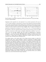
and oscillatory behaviour would occur at higher stiffness values. Figure 2 shows such a
situation, using data recorded for the robotic system described in Section 4. In this figure,
two plots of contact force for a fixed-gain controller tuned for low K
e
are displayed. The low
K
e
contact situation is as expected; however oscillatory behaviour for the high K
e
situation
can clearly be seen. In practical robotic systems, this kind of ‘chattering’ behaviour can have
serious consequences, potentially causing serious damage to the robot and its environment.
Fig. 1. Typical conventional robotic force control scheme
Other major factors contributing to poor, unstable performance include the finite and
relatively low sampling rates of many industrial robot control systems. These problems are
often considerably worsened by the presence of noise, non-linearities and other factors. For
this reason, force controllers of the type described usually require some form of
environment stiffness detection technique to enable the controller gains to be switched
accordingly. The main problem with this process is that it is time consuming, often
involving ‘guarded moves’ to contact in order to enable sufficient data to be collected for the
algorithm to work. Such methods are also vulnerable to the presence of transducer noise,
and are not very effective in situations where K
e
is variable or rapidly changing - for
example during a deburring task (Ow 1997). This also has the effect of slowing down task
execution significantly. Problems such as these have motivated much research into
designing efficient force control schemes, and this is the subject of the next Section.
0 1 2 3 4 5 6 7 8 9 10
-5
0
5
10
15
20
25
30
35
40
Force Response - Measured Force(Blue)
Time (s)
Force (N)
Low Ke
High Ke
Fig. 2. Environmental stiffness effects on the performance of a fixed-gain force controller
Frontiers in Robotics, Automation and Control
4
3. Advanced Force Control Schemes
A large number of force control techniques of varying complexity have been proposed over
the last twenty years (Zhang & Hemami 1997; Whitney 1985). The most basic direct methods
simply transform joint-space torques into a Cartesian-space wrench, either in an open-loop
fashion (which does not require the explicit measurement of forces and torques) or using
inner and outer closed loops for accurate control of joint torques and Cartesian forces,
respectively. However, since most industrial robots have position control loops that are not
easily modified, indirect methods such as those described in the previous Section are often
preferred. As mentioned, these involve modifying either joint or Cartesian position setpoints
in order to control forces by deliberately introducing position control errors and using the
inherent stiffness of the manipulator in different Cartesian directions.
As mentioned, stable force control is particularly difficult to achieve in ‘hard’ or ‘stiff’
contact situations, where the control loop sampling rate may be a limiting factor. In an
attempt to improve stability various methods have been proposed, the simplest being the
addition of compliant devices at the robot wrist (Whitney & Nevins 1979). Another solution
is to employ ‘active compliance’ filters, where force feedback data is digitally filtered to
emulate a passive spring/damper arrangement (Kim et al. 1992). However, both methods
introduce a potentially unacceptable lag. Recent increases in processing power of low-cost
computers has led to an increased interest in ‘intelligent control’ techniques such as those
employing fuzzy logic, artificial neural networks and genetic algorithms (Linkens &
Nyongsa 1996). Where attempts have been made to employ these techniques (specifically
fuzzy logic) in explicit robot force controllers, simulation studies have demonstrated good
tracking performance despite wide variations in environment stiffness, e.g. (Tarokh & Bailey
1997; Seraji 1998), and for specific contact situations, e.g. deburring (Kiguchi & Fukuda
1997). Improved performance using a hierarchical fuzzy force control strategy has also been
demonstrated for various contact situations, such as peg-in-hole insertion (Lin & Huang
1998). A highly successful and generically applicable force control strategy based upon a
Sugeno-style Fuzzy Inference System (FIS) was proposed by Burn et al. (2003), and will be
described in more detail in Section 3.1.
However, these fuzzy techniques are not without problems. In addition to problems
associated with the ‘curse of dimensionality’, i.e. large numbers of rules that must be
evaluated in the inference process, the performance and stability of fuzzy systems are often
difficult to validate analytically (Cao et al. 1998; Wolkenhauer & Edmunds 1997).
Additionally, when compared to more ‘traditional’ control methods such as LQR (Frankin et
al. 1994), the resulting fuzzy designs are more complex, have larger memory requirements
and larger execution times (Bautista & Pont 2006). Such a technique which has proved to be
popular in recent years has been the use of Model Following Control (MFC). Due to its
conceptually simple design and powerful robustness properties, this type of controller has
been found to be particularly suited to industrial applications such as robotics and motion
control (e.g. Li et al. 1998; Osypiuk et al. 2004). Recent investigations have also shown that
MFC-based techniques can be successfully applied in the force control domain (Short &
Burn 2007). The MFC-based force control technique will be investigated further in Section
3.2.
3.1 Fuzzy Approach To Force Control
A method of designing Sugeno-style fuzzy controllers has previously been developed that
Evaluation of Robotic Force Control Strategies using an Open Architecture Test Facility
5
effectively produces a Proportional + Velocity (PV) controller with variable gains, capable of
maintaining acceptable performance irrespective of K
e
(Burn et al. 2003). A block diagram of
the arrangement is shown in figure 3. To design a controller using this method, firstly a
Sugeno-style FIS is created to emulate a conventional PV controller tuned for a high K
e
environment. The FIS is assigned three inputs (f
e
, Δf
e
and Δp), and one output (u), where the
input ranges are measured from conventional system data. The output from the FIS is a
velocity demand. In order to create a linear system, initially only a single Membership
Function (MF) for each input and output is required. By assigning names normal to the
input MF's, and u
1
to the output MF, a rule of the following form produces the desired
linear control surface: IF (f
e
, Δf
e
, Δ
p
) are ‘normal’ then u is u
1
. Note that a consequence of
employing only one rule is that no defuzzification algorithm is required. By employing a
first-order, Sugeno-style FIS, output u
1
is then defined by:
43211
KpKfKfKu
ee
+
Δ
⋅
+
Δ
⋅
+
⋅
=
(1)
where K1 is a positive constant (equal to the forward gain K
p
of a PV controller), K3 a
negative constant (equal to the velocity feedback gain K
v
), and K2 and K4 are - in this case -
set to zero.
Fig. 3. Fuzzy force controller
The choice of MF type is influenced by the concept of data ‘spread’, and the measurement or
calculation of standard deviation data σi from step response tests. For the single rule system
each input is assigned a single Gaussian MF centered at zero, each with a σ
normal
parameter
equal to that of data obtained from tuned step responses at high K
e.
Since the single rule
system emulates a conventional PV controller it suffers the same disadvantages in the face
of variable K
e
. However, having created the initial FIS, it is now possible to modify the
controller using a combination of analytical and intuitive methods.
With the system tuned for high K
e
, during soft contact the maximum value of Δf
e
is reduced.
This reflects an overdamped response, an undesirable effect that can be minimized by
increasing the proportional gain component of the controller output given by equation (1) if
Frontiers in Robotics, Automation and Control
6
lower Δf
e
is ‘detected’ by the fuzzy controller. This is achieved initially by adding a second
Gaussian MF to the Δf
e
input set (low), with a smaller standard deviation σ
Δ
felow
. In addition,
during a dynamic response of a tuned system to a step input, the maximum value of Δp is
inversely proportional to K
e
. In other words, Δp increases during soft contact. A second rule
is thus added to take into account the decrease in Δf
e
relative to the ‘normal’ (desired)
profile, and the relative increase in Δp. By adding a second output of the same form as
equation (1) it is possible to vary the effective gains. Therefore, a rule is added of the form:
IF (Δf
e
is low) AND (Δp is high) then u is u
2
, where u
2
has the same form as u
1
in equation
(1), but with a modified forward gain component K1
a
, equivalent to K
p
tuned for soft contact
such that K1
a
> K1, and σΔp
high
> σΔp
normal
.
The advantage of the method lies in its apparent simplicity, although its success relies upon
the correct determination of the MF parameters, particularly σΔp
high
and σΔp
normal
. Due to
the structured and well-defined methodology utilized in creating the controller design, as a
related work a software design tool was created that automates the process of designing a
fuzzy force controller. The tool includes an iterative method to tune these MF parameters
until acceptable performance is achieved (Burn et al. 2004).
3.2 Model-Based Approach To Force Control
The robust model-based force controller previously described by Short & Burn (2007) is
loosely based around a robust PID strategy discussed in detail by Scokzowski et al. (2005).
The original strategy is based upon a two-loop MFC, containing a nominal model of the
controlled plant and two PID controllers. The block diagram of a basic MFC controller is
shown in figure 4.
Fig. 4. Robust PID based on MFC
In this type of control, the model compensator R
m
(s) is tuned to a nominal model of the
plant M(s); the actual plant P(s) contains bounded uncertainties. The auxiliary controller
Evaluation of Robotic Force Control Strategies using an Open Architecture Test Facility
7
R(s) acts on the difference between the actual process output and the model process output
to modify the model control signal u
m
(s), which is also fed to the plant. In the case of robotic
force control, the model M(s) is simply the second order motion control loop dynamics,
augmented by a free integrator, and a known (base) value of environment stiffness.
Assuming that model is of reasonable quality, the bounded uncertainty in the plant is then
dominated by the environment stiffness K
e
, varying between K
emax
and K
emin
.
If the two loop controllers R(s) and R
m
(s) are simple proportional gains, as shown in Figure
5, then the MFC structure is considerably simplified. The model loop gain K
p
can be tuned
for K
emax
- a relatively trivial task - whilst the auxiliary loop gain K
p
’ can be tuned to
provide an additional control signal should the actual value of K
e
be less than K
emax
.
However, with this type of controller structure it is important to consider the stability
criteria, and provide a bound on the maximum value for K
p
’.
Fig. 5. Robust force controller
If the ‘model loop’ controller R
m
(s) is tuned for stability using a nominal design method on
the plant P(s) augmented by the maximum environmental stiffness gain K
emax
, then the
stability of the overall control strategy is restricted by the roots of the equation:
0)](1)[()(1
=
Δ
+
+
ssMsR
(2)
Where Δ(s) denotes the model perturbations (uncertainty). The objective is to find for a
given plant and bounded uncertainty in the stiffness gain a maximum bound on |R(s)| that
will maintain stability. In the case where the uncertainty exclusively resides in the
environment stiffness gain K
e
, then if the original loop is tuned for K
emax
then M(s)[1+Δ(s)]
in (2) reduces to:
max
)()()](1)[(
e
KsGsPssM
=
=
Δ
+
(3)
Frontiers in Robotics, Automation and Control
8
Where G(s) represents the nominal robot dynamics and has the form (due to the free
integrator in the forward path):
sss
sG
nn
n
2
23
2
2
)(
ωξω
ω
++
=
(4)
Since the controller R(s) in this case is a single gain, K
p
’, using (3) and (4), equation (2) can be
re-written as follows:
0'2
max
22
23
=+++ KeKpsss
nnn
ωωξω
(5)
Applying the Routh-Hurwitz stability criterion (Pippard 1997) for a cubic equation, the
system will be stable if all the co-efficients in the left of (5) are positive, and the following
criterion is satisfied:
max
22
'2 KeKp
nnn
ωωξω
≥
(6)
Re-arranging (6) gives a stability limit for the controller gain K
p
’
max
as follows:
max
max
2
'
Ke
Kp
n
ξω
=
(7)
Thus if the gain K
p
’ is chosen between the limits:
max
'' KpKpKp
<
<
(8)
The controller will be stable for unknown environment gains in the range 0 < K
e
≤ K
emax
; as
for all gains below K
emax
, the stability criteria of (6) holds. Clearly, the formulation of these
two controllers follows two distinct paths. The first is mainly based on an intuitive, heuristic
formulation, while the second is based on a more thorough analytical approach. In Section 5,
experimental results are presented for both controllers applied to an experimental test
facility, which is described in the following Section.
4. Experimental Test Facility
4.1 Description
A research facility, previously described in detail (Burn & Short 2000; Short 2003), has been
developed in the form of a planar robot arm and PC-based open architecture controller. The
Evaluation of Robotic Force Control Strategies using an Open Architecture Test Facility
9
robots joints are manufactured from toughened ABS plastic, and are actuated by brushless
servomotors (with digital servoamplifiers). The control loop for each axis is closed via a
multitasking DSP embedded in a Delta Tau® Programmable Multi-Axis Controller (PMAC)
motion control card, installed into the PC. Each axis has an individual PID controller with
feed forward control to enable accurate velocity and position profile following. A six-axis
force/torque sensor was developed in-house for the project, and is employed in the current
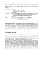
study. The robot arm is shown photographically in figure 6, and schematically in figure 7.
Fig. 6. Robotic test facility
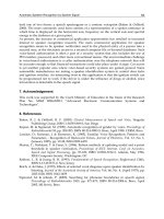
Fig. 7. Schematic of test facility
Frontiers in Robotics, Automation and Control
10
Fig. 8. Application software screenshots
The controller for this robot was developed with a completely ‘open architecture’ in mind
(Ford 1984), with a view to the integration and implementation of novel sensor-based
control strategies. The software is based on a three-layered open architecture, as described
by Short (2000 & 2003). It features the ability to design and integrate advanced control
strategies into the controller, and via the use of an ActiveX® link allows the full
functionality of software packages such as Matlab® to be embedded within the controller
software. The sensors required to perform these control strategies in real-time are integrated
into the system using flexible fieldbus technologies. The underlying kinematic and dynamic
models of the robot can be changed to suit the current configuration, allowing the controller
to be tailored to any particular arm configuration or drive system. A modular robot
programming language - named Sunderland ARm Language (SARL) - was developed for
Evaluation of Robotic Force Control Strategies using an Open Architecture Test Facility
11
the controller. Screenshots of the Windows® XP version of the application software are
shown in figure 8.
The force controllers described in the previous Section were coded in the C programming
language, compiled and added into the controller’s modular software component library.
Several experiments were then performed using the resulting software. Each experiment
involved a specific contact situation, where the robot first approached the contact surface
with constant velocity, and subsequently applied a force of 30 N. The contact surface was
varied in each experiment, and two surfaces were used; hard (steel) and soft (plastic). In
order to reliably detect the contact surface, the end effector was fitted with a Baumer
Electric® photoswitch which was calibrated to signal with high accuracy when a solid object
was within a distance of 5mm. The sensor was integrated into the controller architecture
using a Controller Area Network connection (CAN) fieldbus. The robot was programmed
approached the contact surface at a slow jog speed until this signal was made, then switched
to force control mode. The sample rate employed was 200 Hz in each experiment, and the
measured force was prefiltered using a first-order low pass filter with cut off frequency of
0.01 Hz. In the following section, the parameters that were used to design the controllers are
described.
4.2 Controller Design
From a previous identification exercise, the model parameters of each joint of the robot arm
and the environment stiffness limits were determined to be as follows (Short 2003):
mmNKmmNK
srad
ee
n
/11,/168
,1,/244
minmax
==
=
=
ξ
ω
(9)
Using these parameters, the controllers were designed as follows. In both cases, the nominal
loop gain K
p
was tuned to a value of 0.02 to give the desired transient performance – a 95%
rise time of approximately 2 seconds with minimal overshoot. For the fuzzy method, the
nominal gain for contact at low K
e
could then simply be calculated as follows:
3.0
min
max
=⋅
⎟
⎟
⎠
⎞
⎜
⎜
⎝
⎛
=
p
e
e
plow
K
K
K
K
(10)
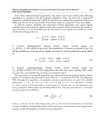
This information was then used as input to the controller design software (Burn et al. 2004),
and the controller tuning algorithm was run for 200 iterations to produce the final fuzzy
controller that was utilized in the experiment. The highly non-linear I/O surface of the
controller is illustrated by figure 9, which shows a plot of F
e
and ΔF
e
versus controller
output u. In the MFC controller, the value of the nominal loop gain K
p
was then used to
design the value of K
p
’
max
calculated as given by (7) to have a value of 2.9. A value of K
p
’ =
1.5 was therefore chosen for the experiments, as this gave good performance and remained
well below the stability limit. The experimental comparison of the controllers is discussed in
the following Section.
Frontiers in Robotics, Automation and Control
12
-1
-0.5
0
0.5
1
-5
0
5
-1.5
-1
-0.5
0
0.5
1
1.5
x 10
-3
Fe
dFe
u
Fig. 9. Fuzzy controller I/O surface
5. Experimental Results and Analysis
This section begins by presenting the results of the contact experiments described in the
previous Section, beginning with the FIS-based controller. Figure 10 shows the responses of
this controller when applying a force to the hard (steel) and soft (plastic) surfaces.
Considering now the MFC-based controller, figure 11 shows the responses of this controller
when applying a force to the same surfaces. The very small negative force indicated before
contact with the surface was made (at approx 1s) was due to a small drift in the calibration
of the force sensor whilst moving in free space.
These figures demonstrate the effectiveness of both approaches; comparing these figures
with the responses shown in figure 2, the fixed gain controller, it can be seen that the
responses display little sign of instability. The compensation added by the adaptation of
loop gains in the FIS controller, and the extra loop and forcing gain in the MFC controller
can clearly be seen; in all cases, a very similar transient response is seen. There is a slight
overshoot in the response of the fuzzy method when contacting the hard surface, and it can
be seen that the steady-state behaviour seems to be slightly less stable than the MFC
controller.
Evaluation of Robotic Force Control Strategies using an Open Architecture Test Facility
13
0 1 2 3 4 5 6 7 8 9 10
-5
0
5
10
15
20
25
30
35
Force Response - Measured Force(Blue)
Time (s)
Force (N)
Low Ke
High Ke
Fig. 10. Contact force profile for the FIS-based controller
0 1 2 3 4 5 6 7 8 9 10
-5
0
5
10
15
20
25
30
35
Force Response - Measured Force(Blue)
Time (s)
Force (N)
Low Ke
High Ke
Fig. 11. Contact force profile for the MFC-based controller
Frontiers in Robotics, Automation and Control
14
In addition to these response measurements, the Integral of Time by Absolute Error (ITAE)
for each of the responses was calculated and is shown in table 1. The ITAE is a useful
measure of system performance in the time-domain and is given by equation (11) (Franklin
et al. 1994). This table includes additional information pertaining to each method, including
the approximate Source-Lines-Of-Code (SLOC) needed for each implementation, the
measured run-time overheads (i.e. CPU execution time per iteration, in milliseconds) and a
relative measure of the ‘design effort’ needed for each controller. The latter was classified
subjectively into either a LOW or HIGH category.
∫
= dtteITAE
(11)
Performance Measures
Controller ITAE (low) ITAE (high) SLOC CPU (ms) Effort
FIS
227.1 247.1 1000+ 2.05 HIGH
MFC
215.6 220.1 <100 0.15 LOW
Table 1. Summary of controller comparative data
The ITAE data further illustrates the performance of both force control methods. As
expected, the FIS controller had a higher overall ITAE value for both contact situations, and
there was a larger measurable difference between the two response values. This reflects the
observation that the FIS controller demonstrated a faster response with a slight overshoot at
the higher stiffness gain value. Although a slight difference exists between the responses for
the MFC controller, as can be seen from the responses its performance seems more
predictable and it does not ‘hunt’ around the setpoint to the same level as the FIS. This is
best attributed to the fact that close to the setpoint, the model error – and hence the forcing
control signal – are close to zero. The FIS controller, however, seems to be sensitive to noise
in the error signal; especially through the Δf
e
input, thus allowing small gain adaptations to
take place in the region of the setpoint. These small gain adaptations are magnified by the
resulting changes in the measured Δ
p
, exacerbating the problem slightly. Despite these
observations, it can be argued that the overall performance of both controllers is acceptable
for most practical situations.
The SLOC measure gives a rough indication of the complexity of the code required for the
implementation of the controllers. In this respect it can be seen that the MFC has a huge
advantage over the FIS. As well as the main implementation code, e.g. the calculation of
error signals for the controller inputs, the FIS method requires extensive code to implement
the fuzzification, logical inference and de-fuzzification subroutines. These will – generally –
cause a large increase in the code size, either from the inclusion of specialised library files or
from a direct implementation of the underlying mathematical equations. The MFC
controller, however, simply requires the updating of a third-order equation and simple
addition/subtraction and multiplication to generate the control effort. The increased
complexity of the FIS method is reflected by an almost 14-fold increase in the CPU
Evaluation of Robotic Force Control Strategies using an Open Architecture Test Facility
15
overheads required at each sample iteration to generate the control signal. In addition,
although the design methodology proposed for the MFC controller guarantees its stability at
present, no such guarantee can be placed on the FIS-based controller. To summarize, it was
reflected that the amount of effort required to implement the FIS method was significantly
higher than the MFC, from both the control and software design perspectives.
6. Conclusion
This chapter has been concerned with the practical realisation of robotic force control. It has
been shown that many potential difficulties arise when implementing a force control
method, including stability and robustness problems associated with applications where
environmental uncertainty exists, and with sampling and control limitations related to the
basic operation of many tradition robot controllers.
Force control remains an ongoing area of research; however, in recent years a variety of
efficient solutions to many of these problems have been proposed. This chapter has
considered two novel methods in depth, and has described a series of experiments to
perform a direct real-time comparison of the controllers using an open-architecture test
facility. Whilst the results generated indicate slightly better behaviour for the MFC-based
method, in practical situations both methods were deemed acceptable and a considerable
improvement over a fixed-gain controller. Based on the analysis of design effort, system
stability and incurred CPU overheads, however, this chapter concludes that the MFC-based
controller has significant advantages over the FIS-based design.
Future work in this area will include analysis of situations where PD controllers are used as
the MFC loop compensators, and also consider the effects of model mismatch (which is
inevitable if the methodology is to be applied to larger-scale industrial robots). Further work
will also consider implementation on both controllers on a 6-DOF manipulator to further
investigate and contrast the two approaches.
7. References
Bautista, R. & Pont, M.J. (2006). Is fuzzy logic a practical choice in resource-constrained
embedded control systems implemented using general-purpose microcontrollers?
In Proceedings of the 9th IEEE International Workshop on Advanced Motion Control,
Istanbul, Vol. 2, pp.692-697.
Bicker, R., Burn, K., Glennie, D. & Ow, S.M. (1994). Application of force control in
telerobotics, Proc Int Conf EURISCON '94, Malaga, Spain.
Burn, K, Home, G, Short, M. & Bicker, R. (2004). A software tool for automating the design
of robot fuzzy force controllers, Robotica, Vol. 23(2), pp. 247-256.
Burn, K, Short, M. & Bicker, R. (2003). Adaptive and nonlinear fuzzy force control
techniques applied to robots operating in uncertain environments, Journal of Robotic
Systems, Vol. 20(7), pp. 391-400.
Burn, K. & Short, M. (2000). Development of a generic robot controller architecture for
advanced and intelligent robots, In: Proc. 14th Int. Conf. On Systems Eng. (ICSE
2000), Vol. 1, pp. 92-97.
Cao, S.G., Rees, N.W. & Feng, G. (1998). Lyapunov-like stability theorems for continuous-
time fuzzy control systems. Int J Control, Vol. 69(1), pp. 49-64.
Frontiers in Robotics, Automation and Control
16
Engelberger, JF. (1980). Robots in practice, Kogan Page; London, UK.
Ford, WE. (1984). What is an open architecture robot controller? In: Proc 9th IEEE Int. Symp.
on Intelligent Control, pp. 27-32.
Franklin, G.F., Powell, J.D. & Emani-Naeini, A. (1994). Feedback Control Of Dynamic Systems,
Addison-Wesley Publishing, Reading Massachusetts, third edition.
Kiguchi, K. & Fukuda, T. (1997). Intelligent position/force controller for industrial robot
manipulators – application of fuzzy neural networks, IEEE Trans Industrial
Electronics, Vol. 44(6), pp. 753-761.
Kim, W.S., Hannaford, B. & Bejczy, A.K. (1992). Force Reflection and Shared Compliant
Control in Operating Telemanipulators with Time Delay, IEEE Trans on Robotics and
Automation, Vol. 8(2), pp. 176-185.
Li, G., Tsang, K.M. & Ho, S.L. (1998). A novel model following scheme with simple structure
for electrical position servo systems, Int. J. Syst. Sci., Vol. 29(9), pp. 959–969.
Lin, S.T. & Huang, A.K. (1998). Hierarchical Fuzzy Force Control for Industrial Robots, IEEE
Trans on Industrial Electronics, Vol. 45(4), pp. 646-653.
Linkens, D.H. & Nyongesa, H.O. (1996). Learning systems in intelligent control: an appraisal
of fuzzy, neural and genetic algorithm control applications, IEE Proc Control Theory
Appl, Vol. 143(4), pp. 367-386.
Osypiuk, R., Finkemeyer, B. & Wahl, F.M. (2004). Forward-model based control system for
robot manipulators, Robotica, Vol. 22(2), pp. 155–161.
Ow, S.M. (1997). Force Control in Telerobotics, PhD Thesis, University of Newcastle upon
Tyne, UK.
Pippard, A.B. (1997). Response & Stability: An Introduction to the Physical Theory, Cambridge
University Press.
Seraji, H. (1998). Nonlinear and Adaptive Control of Force and Compliance in Manipulators,
Int J Robotics Research, Vol. 17(5) pp. 467-484.
Short, M. (2003). A Generic Controller Architecture for Advanced and Intelligent Robots, PhD.
Thesis, University of Sunderland, UK.
Short, M. & Burn, K. (2007). Robust and Stable Robotic Force Control, In: Proceedings of the
4th International Conference on Informatics in Control, Automation and Robotics
(ICINCO'07), Angers, France, May 09-12.
Skoczowski, S., Domek, S., Pietrusewicz, K. & Broel-Plater, B. (2005). A Method for
Improving the Robustness of PID Control, IEEE Trans Industrial Electronics, Vol.
52(6), pp. 1669-1676.
Tarokh, M. & Bailey, S. (1997). Adaptive fuzzy force control of manipulators with unknown
environment parameters, J Robotic Sys, Vol. 14(5), pp. 341-353.
Whitney, D.E. (1985). Historical Perspective and State of the Art in Robot Force Control, Int J
Robotics Res, Vol. 6(1), pp. 3-14.
Whitney, D.E. & Nevins, J.L. (1979). What is the Remote Centre Compliance (RCC) and what
can it do? In: Proc Int Symp on Industrial Robots, Washington DC, pp. 135-152.
Wolkenhauer, O. & Edmunds, J.M. (1997). A critique of fuzzy logic in control, Int J Electrical
Engineering Education, Vol. 34(3), pp. 235-242.
Zhang, G. & Hemami, A. (1997). An Overview of Robot Force Control, Robotica
, Vol. 15, pp.
473-482.
2
Towards a Roadmap for Effective Handset
Network Test Automation
Clauirton A. Siebra, Andre L. M. Santos & Fabio Q. B. Silva
CIN/Samsung Laboratory of Research and Development
1
- UFPE
Brazil
1. Introduction
In recent years, wireless networks have presented a significant evolution in their technology.
While first-generation networks, based on analog signalling, were targeted primarily at
voice and data communications occurring at low data rates, we have recently seen the
evolution of second- and third-generation wireless systems that incorporate the features
provided by broadband networks (Garg, 2001). In addition to supporting mobility,
broadband networks also aims to support multimedia traffic, with quality of service (QoS)
assurance. Therefore the evolution from 2G to 3G wireless technology bears the promise of
offering a wide range of new multimedia services to mobile subscribers (De Vriendt et al.,
2002).
In this context, handset devices are following this ongoing network evolution and taking
advantage of this technological update to offer a broad variety of resources and applications
to their users. In fact, handset development has evolved into a complex engineering process,
mainly because of the recent network capabilities supported by new mobile communication
and computer technology advances (memory speed and size, processing power, better
resources for information delivery, etc.). This scenario has increased the demand on the test
phase of handset development, which is required to apply more extensive and efficient
evaluation procedures so that the final product meets the fast time-to-market goals and can
compete in the global marketplace.
While the number and complexity of tests are increasing, test centers need to decrease their
test execution time. The quicker a specific handset is evaluated and delivered to the market,
the better will be its chances to compete with other models. Therefore we have a
contradiction: we need to increase the number of tests and decrease the test time.
Furthermore, this contradiction can lead us to reduce the quality of our test processes.
Test automation is one alternative to this emerging scenario, because it enables tests to be
launched and executed without the need for user intervention. Thus, common delays and
errors associated with the manipulation of test parameters by humans can be avoided.
1
The results presented in this chapter have been developed as part of a collaborative project between Samsung
Institute for Development of Informatics (Samsung/SIDI) and the Centre of Informatics at the Federal University
of Pernambuco (CIn/UFPE), financed by Samsung Eletronica da Amazonia Ltda., under the auspices of the
Brazilian Federal Law of Informatics no. 8248/91.