The Design of Rolling Bearing Mountings Part 2 docx
Bạn đang xem bản rút gọn của tài liệu. Xem và tải ngay bản đầy đủ của tài liệu tại đây (518.47 KB, 15 trang )
4 Electric motor for domestic appliances
Operating data
Power 30 W; speed 3,500 min
–1
.
Bearing selection
Quiet running is the prime requirement for domestic
appliance motors. The noise level of a motor is influ-
enced by bearing quality (form and running accuracy),
bearing clearance and the finish of the shaft and end
cap bore.
Today, the quality of standard bearings already ade-
quately meets the common noise requirements.
Zero-clearance operation of the bearings is achieved by
a spring washer lightly preloading the bearings in the
axial direction.
The bearing seats on the shaft and in the end cap bores
must be well aligned. To allow the spring washer to
adjust the bearings axially, the outer rings have slide fits
in the end caps.
A deep groove ball bearing FAG 626.2ZR is provided
on the collector side, and an FAG 609.2ZR.L91 on
the other side.
Suffixes
.2ZR Bearing with shields on both sides; they form a
gap-type seal
L91 special grease filling (Arcanol L91)
Bearing dimensioning
The shaft diameter is usually dictated by the machine
design, and as a result the bearings are sufficiently di-
mensioned with regard to fatigue life. Fatigue damage
hardly ever occurs; the bearings reach the required life
of between 500 and 2,000 hours.
Machining tolerances
Shaft to j5; end cap bore to H5
The bore tolerance H5 provides the slide fit required
to permit free axial alignment of both bearings.
Sealing, lubrication
Grease lubrication with lithium soap base grease of con-
sistency number 2 with an especially high degree of
cleanliness. It is characterized by its low friction. The
overall efficiency of this motor is considerably influ-
enced by the frictional moment of the ball bearings.
The bearings with shields (.2ZR design) are prelubri-
cated with grease, i.e. regreasing is not required. The
gap-type seal formed by the shields offers adequate
protection against contamination under normal ambi-
ent conditions.
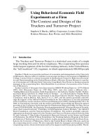
4: Electric motor for domestic appliances
5 Drum of a domestic washing machine
Operating data
Capacity 4.5 kg dry mass of laundry
(weight G
w
= 44 N);
Speeds: when washing 50 min
–1
when spinning after prewash cycle 800 min
–1
when dry spinning 1,000 min
–1
Bearing selection
The domestic washing machine is of the front loading
type. The drum is overhung and pulley-driven.
Bearing selection depends on the journal diameter
which is determined by rigidity requirements, and also
on the weight and unbalanced loads. Very simplified
data is assumed for bearing load determination, on
which the bearing dimensions are based, since loads
and speeds are variable.
Domestic washing machines generally have several,
partly automatic, washing cycles with or without spin-
ning. During the actual washing cycle, i.e. a cycle
without spinning, the drum bearings are only lightly
loaded by the weight resulting from drum and wet
laundry. This loading is unimportant for the bearing
dimensioning and is thus neglected. The opposite
applies to the spinning cycle: Since the laundry is un-
evenly distributed around the drum circumference, an
unbalanced load arises which, in turn, produces a large
centrifugal force. The bearing dimensioning is based
on this centrifugal force as well as on the weights of the
drum, G
T
, and the dry laundry, G
w
. The belt pull is
generally neglected.
The centrifugal force is calculated from:
F
Z
= m · r ·
2
[N]
where
m = G
U
/g [N · s
2
/m]
G
U
Unbalanced load [N]. 10 35 % of the dry
laundry capacity is taken as unbalanced load.
g Acceleration due to gravity = 9.81 m/s
2
r Radius of action of unbalanced load [m]
Drum radius = d
T
/ 2 [m]
Angular velocity = π · n / 30 [s
–1
]
n Drum speed during spinning [min
–1
]
The total force for determination of the bearing loads
thus is: F = F
Z
+ G
T
+ G
W
[N]
This load is applied to the washing drum centre.
The bearing loads are:
Bearing A
F
rA
=
F ·
l
2
[N]
a
Bearing B
F
rB
=
F ·
l
1
[N]
a
Bearing dimensioning
The bearings for domestic washing machines are
dimensioned for an index of dynamic stressing
f
L
= 0.85 1.0.
These values correspond to a nominal life of
300 500 hours of spinning.
In the example shown a deep groove ball bearing FAG
6306.2ZR.C3 was selected for the drum side and a
deep groove ball bearing FAG 6305.2ZR.C3 for the
pulley side.
The bearings have an increased radial clearance C3 and
are sealed by shields (.2ZR) at both sides.
Machining tolerances
Due to the unbalanced load G
U
,the inner rings are
subjected to point load, the outer rings to circumferen-
tial load. For this reason, the outer rings must have a
tight fit in the housing; this is achieved by machining
the housing bores to M6. The fit of the inner rings is
not as tight; drum journal to h5. This ensures that the
floating bearing is able to adjust in the case of thermal
expansion. A loose fit also simplifies mounting.
Lubrication, sealing
The bearings, sealed at both sides, are prelubricated
with a special grease, sufficient for the bearing service
life. There is an additional rubbing-type seal at the
drum side.
Pulley
Drum
5: Drum mounting of a domestic washing machine
6 Vertical-pump motor
Operating data
Rated horsepower 160 kW; nominal speed 3,000 min
–1
;
Rotor and pump impeller mass 400 kg; pump thrust
9 kN, directed downwards; type V1.
Bearing selection
The selection of the bearings is primarily based on the
main thrust, which is directed downwards. It is made
up of the weight of the rotor and and pump impeller
(4 kN), the pump thrust (9 kN) and the spring preload
(1 kN). When the motor idles the pump thrust may be
reversed so that the bearings have, briefly, to accom-
modate an upward axial load of 4 kN, as well.
The radial loads acting on the bearings are not exactly
known. They are made up by the unbalanced magnetic
pull and potential unbalanced loads from the rotor
and pump impeller. However, field experience shows
that these loads are sufficiently taken into account by
taking 50 % of the rotor and pump impeller mass,
which in this case is 2 kN.
In the example shown, the supporting bearing is an
angular contact ball bearing FAG 7316B.TVP which
has to accommodate the main thrust. To ensure that
no radial force acts on the bearing this part of the
housing is radially relieved to clearance fit E8.
In normal operation, the deep groove ball bearing
FAG 6216.C3 takes up only a light radial load and the
axial spring preload; in addition, the thrust reversal
load of the idling motor has to be accommodated.
As a result, the rotor is vertically displaced in the up-
ward direction (ascending distance) which is limited
by the defined gap between deep groove ball bearing
face and end cap. To avoid slippage during the thrust
reversal stage, the angular contact ball bearing is sub-
jected to a minimum axial load by means of springs.
On the pump impeller side a cylindrical roller bearing
FAG NU1020M1.C3 acts as the floating bearing. As it
accommodates the unbalanced loads from the pump
impeller both the inner and the outer ring are fitted
tightly.
The cylindrical roller bearing design depends on the
shaft diameter of 100 mm, which in turn is dictated by
strength requirements. Due to the relatively light radi-
al load, the lighter series NU10 was selected.
Machining tolerances
Cylindrical roller bearing: Shaft to m5; housing
to M6
Deep groove ball bearing: Shaft to k5; housing
to H6
Angular contact ball bearing: Shaft to k5, housing
to E8
Lubrication
The bearings are lubricated with FAG rolling bearing
grease Arcanol L71V and can be relubricated.
Replenishment quantity
– for the floating bearing 15 g
– for the locating bearing 40 g
The relubrication interval is 1,000 hours. The spent
grease is collected in annular cover chambers provided
below the bearing locations.
6: Rotor bearing arrangement of a vertical-pump motor
7 Mine fan motor
Operating data
Rated horsepower 1,800 kW; speed n = 750 min
–1
;
Axial load F
a
= 130 kN; radial load F
r
= 3.5 kN;
the bearings are vertically arranged.
Bearing selection
The axial load of 130 kN is made up of the weight of
the rotor and the two variable top and bottom fan im-
pellers as well as the thrust of these fan impellers. They
are supported by the upper thrust bearing.
The radial loads on vertical motors are only guiding
loads. They are very small and generally result from the
unbalanced magnetic pull and the potential rotor un-
balanced load. In the example shown, the radial load
per bearing is 3.5 kN. If the exact values are not
known, these loads can be sufficiently taken into
account, assuming that half the rotor weight acts as the
radial load at the rotor centre of gravity.
The upper supporting bearing is a spherical roller
thrust bearing FAG 29260E.MB. Radial guidance is
ensured by a deep groove ball bearing FAG 16068M
mounted on the same sleeve as the supporting bearing
and accommodating the opposing axial loads on the
rotor. Axial guidance is necessary for transporting and
mounting as well as for motor idling. In this operating
condition the counterflow of air can cause reversal of
rotation and thrust. The axial displacement is limited
to 1 mm in the upward direction so that the spherical
roller thrust bearing does not lift off. Springs arranged
below the housing washer (spring load 6 kN) ensure
continuous contact in the bearings.
Radial guidance at the lower bearing position is pro-
vided by a deep groove ball bearing FAG 6340M; it is
mounted with a slide fit as the floating bearing. Since
it is only lightly loaded, it is preloaded with springs of
3 kN.
Bearing dimensioning
Spherical roller thrust bearing FAG 29260E.MB has a
dynamic load rating of C = 1430 kN. The index of dy-
namic stressing f
L
= 4.3 is calculated with the axial load
F
a
= 130 kN and the speed factor for roller bearings
f
n
= 0.393 (n = 750 min
–1
). The nominal life
L
h
= 65,000 hours.
Based on the operating viscosity of the lubricating oil
(viscosity class ISO VG150) at approx. 70 °C, the
rated viscosity
1
and the factors K
1
und K
2
, a basic a
23II
value of about 3 is determined. The cleanliness factor s
is assumed to be 1. The attainable life L
hna
of the thrust
bearing is longer than 100,000 hours and the bearing
is therefore sufficiently dimensioned. The two radial
bearings are also sufficiently dimensioned with the in-
dex of dynamic stressing f
L
> 6.
Machining tolerances
Upper bearing location
Spherical roller thrust bearing: Shaft to k5; housing
to E8
Deep groove ball bearing: Shaft to k5; housing
to H6
Lower bearing location
Deep groove ball bearing: Shaft to k5; housing
to H6
Lubrication, sealing
Thrust and radial bearings at the upper bearing loca-
tion are oil-lubricated.
The spherical roller thrust bearing runs in an oil bath
and, due to its asymmetrical design, provides automat-
ic circulation from the inner to the outer diameter. A
tapered oil feeder and angled oilways supply the upper
bearing. A retaining and a flinger ring ensure oil sup-
ply during start-up.
The lower bearing is grease-lubricated with provision
for relubrication and a grease valve. Both bearing loca-
tions are labyrinth-sealed.
7: Rotor bearing arrangement of a mine fan motor
8 Rotor of a wind energy plant
Wind energy plants are among the alternative and en-
vironmentally friendly energy sources. Today, they
generate powers of up to 3,200 kW. There are horizon-
tal-rotor systems and vertical-rotor systems. The wind
energy plant WKA60 is 44 meters high and features a
three-blade horizontal rotor with a diameter of 60 m.
Operating data
Nominal speed of the three-blade rotor = 23 min
–1
;
gear transmission ratio i = 1:57.4; electrical power
1,200 kW at a nominal rotor speed of the generator of
n = 1,320 min
–1
.
Bearing selection
A service life of 20 years was specified. To support the
overhung blade rotor, spherical roller bearings FAG
231/670BK.MB (dimensions 670 x 1,090 x 336 mm)
were selected for the locating bearing location and FAG
230/900BK.MB (dimensions 900 x 1,280 x 280 mm)
for the floating bearing location.
Bearing dimensioning
The recommended value for dimensioning the main
bearings of wind energy plants is P/C = 0.08 0.15.
The varying wind forces, causing vibrations, make it
difficult to exactly determine the loads to be accom-
modated by the bearings. A nominal life of L
h
>
130,000 h was specified. For this reason, the mean
equivalent load is, as a rule, determined on the basis of
several load cases with variable loads, speeds and per-
centage times. The locating bearing of the WKA60
plant is subjected to radial loads of F
r
= 400 1,850 kN
and thrust loads of F
a
= 60 470 kN. The floating bear-
ing may have to accommodate radial loads of
F
r
= 800 1,500 kN.
For the locating bearing, the radial and axial loads to be
accommodated yield a mean equivalent dynamic load
of P = 880 kN. For the bearing FAG 231/670BK.MB
with a dynamic load rating of C = 11,000 kN this
yields a load ratio of P/C = 880/11,000 = 0.08.
The floating bearing FAG 230/900BK.MB accommo-
dates a mean radial force of F
r
= P = 1,200 kN. With a
dynamic load rating of 11,000 kN a load ratio of
1,200/11,000 = 0.11 is obtained.
The life values calculated for the normally loaded
spherical roller bearings (in accordance with DIN ISO
281) are far above the number of hours for 20-year
continuous operation.
Mounting and dismounting
To facilitate mounting and dismounting of the bear-
ings, they are fastened on the shaft by means of hy-
draulic adapter sleeves FAG H31/670HGJS and FAG
H30/900HGS. Adapter sleeves also allow easier ad-
justment of the required radial clearance.
The bearings are supported by one-piece plummer
block housing of designs SUB (locating bearing) and
SUC (floating bearing). The housings are made of cast
steel and were checked by means of the finite-element
method.
Machining tolerances
The withdrawal sleeve seats on the rotor shaft are
machined to h9 and cylindricity tolerance IT5/2 (DIN
ISO 1101).
The bearing seats in the housing bore are machined to
H7; this allows the outer ring of the floating bearing to
be displaced.
Lubrication, sealing
The bearings are lubricated with a lithium soap base
grease of penetration class 2 with EP additives (FAG
rolling bearing grease Arcanol L186V).
The housings are sealed on both sides by means of a
double felt seal. A grease collar around the sealing gap
prevents ingress of dust, dirt and, possibly, splash
water.
Wind energy plant, schematic drawing
Rotor floating bearing
Rotor brake
Rotor locating bearing
Coupling
Gear
electr. switch unit
and control system
Generator
Rotor hub with rotor
adjustment mechanism
Rotor
blade
Foundation
Wind tracker
Tower
Mains connection
Rotor
blade
bearing
8: Rotor shaft bearings of a wind energy plant
9–18 Work spindles of machine tools
The heart of every machine tool is its main or work
spindle and its work spindle bearings. The main qual-
ity characteristics of the spindle-bearing system are
cutting volume and machining precision. Machine
tools are exclusively fitted with rolling bearings of in-
creased precision; mainly angular contact ball bearings
and spindle bearings (radial angular contact ball bear-
ings with contact angles of 15° and 25°, respectively),
double-direction angular contact thrust ball bearings,
radial and thrust cylindrical roller bearings and, occa-
sionally, tapered roller bearings.
Depending on the performance data required for a
machine tool, the spindle bearing arrangement is de-
signed with ball or roller bearings based on the follow-
ing criteria: rigidity, friction behaviour, precision,
speed suitability, lubrication and sealing.
Out of a multitude of possible spindle bearing arrange-
ments for machine tools a few typical arrangements
have proved to be particularly suitable for application
in machine tools (figs. a, b, c).
Dimensioning
Usually, a fatigue life calculation is not required for the
work spindles since, as a rule, to achieve the required
spindle and bearing rigidity, bearings with such a large
bore diameter have to be selected that, with increased
or utmost cleanliness in the lubricating gap, the bear-
ings are failsafe. For example, the index of dynamic
stressing f
L
of lathe spindles should be 3 4.5; this cor-
responds to a nominal life of L
h
= 15,000 50,000 h.
Example: The main spindle bearing arrangement of a
CNC lathe (fig. a) is supported at the work end in
three spindle bearings B7020E.T.P4S.UL in tandem-
O-arrangement (contact angle ␣
0
= 25°, C = 76.5 kN,
C
0
= 76.5 kN). At the drive end, the belt pull is ac-
commodated by a double-row cylindrical roller bear-
ing NN3018ASK.M.SP. The cutting forces cause 50 %
each of the axial reaction forces for the two tandem-
arranged spindle bearings. The front bearing at the
work end accommodates 60 % of the radial forces. It is
loaded with F
r
= 5 kN, F
a
= 4 kN at n = 3,000 min
–1
.
If the bearings are lubricated with the lithium soap
base grease FAG Arcanol L74V (base oil viscosity
23 mm
2
/s at 40 °C), an operating viscosity of
= 26 mm
2
/s will be obtained at an operating temper-
ature of 35 °C. With the mean bearing diameter
d
m
= 125 mm and the speed n = 3,000 min
–1
a rated
viscosity of
1
= 7 mm
2
/s is obtained.
This yields a viscosity ratio = /
1
≈ 4; i. e. the rolling
contact areas are fully separated by a lubricant film.
With = 4, a basic a
23II
factor of 3.8 is obtained from
the a
23
diagram. Since the bearings, as a rule, are rela-
tively lightly loaded (f
s*
> 8), a very good cleanliness
factor (s = infinite) is obtained with increased (V = 0.5)
and utmost (V = 0.3) cleanliness. Consequently, the
factor a
23
(a
23
= a
23II
· s), and thus the attainable life
(L
hna
= a
1
· a
23
· L
h
) becomes infinite; the bearing is
failsafe.
So, as long as f
s*
≥ 8 and the main spindle bearings are
lubricated well ( ≥ 4), only the cleanliness in the lu-
bricating gap determines whether the bearing is failsafe
or not.
a: Spindle bearing arrangement with universal-design spindle bear-
ings (spindle bearing set), subjected to combined load, at the work
end and a single-row or double-row cylindrical roller bearing at the
drive end which accommodates only radial loads.
b: Spindle bearing arrangement with two tapered roller bearings in
O arrangement. The bearings accommodate both radial and axial
loads.
c: Spindle bearing arrangement with two double-row cylindrical
roller bearings and a double-direction angular contact thrust ball
bearing. Radial and axial loads are accommodated separately.
9 Drilling and milling spindle
Operating data
Input power 20 kW; range of speed 11 2,240 min
–1
.
Bearing selection
Radial and axial forces are accommodated separately.
The radial bearings are double-row cylindrical roller
bearings – an FAG NN3024ASK.M.SP at the work
end and an FAG NN3020ASK.M.SP at the opposite
end. The double-direction angular contact thrust ball
bearing FAG 234424M.SP guides the spindle in axial
direction. This bearing has a defined preload and
adjustment is, therefore, not required.
Machining of the housing bore is simplified in that the
nominal outside diameters of the radial and thrust
bearings are the same. The O.D. tolerance of the angu-
lar contact thrust ball bearing is such as to provide a
loose fit in the housing.
Lubrication, sealing
Circulating oil lubrication.
The labyrinth seal at the work end consists of ready-to-
mount, non-rubbing sealing elements. The inner laby-
rinth ring retains the lubricating oil, the outer laby-
rinth ring prevents the ingress of cutting fluid.
Machining tolerances
Bearing Seat Diameter Form tolerance Axial runout tolerance
tolerance (DIN ISO 1101) of abutment shoulder
Cylindrical roller bearing Shaft, tapered Taper 1:12 IT1/2 IT1
Housing K5 IT1/2 IT1
Angular contact thrust bearing Shaft h5 IT1/2 IT1
Housing K5 IT1/2 IT1
9: Drilling and milling spindle
10 NC-lathe main spindle
Operating data
Input power 27 kW;
maximum spindle speed 9,000 min
–1
.
Bearing selection
The main requirements on this bearing arrangement
are an extremely good speed suitability, rigidity, and
accurate guidance of the work spindle. At the work
end, a spindle bearing set FAG B7017C.T.P4S.DTL
in tandem arrangement is provided; at the drive end, a
spindle bearing set FAG B71917C.T.P4S.DTL in
tandem arrangement.
The bearings are lightly preloaded (UL) and have an
increased precision (P4S).
The arrangement has no floating bearing; it is a rigid
locating bearing system. Both bearing groups together
form an O arrangement.
Bearing dimensioning
The size of the bearings is primarily based on the spin-
dle rigidity required, i. e. on the largest possible spin-
dle diameter. The fatigue life of the bearings is taken
into account for dimensioning but it does not play a
dominating role in practice.
Main spindle bearings do not normally fail due to ma-
terial fatigue but as a result of wear; the grease service
life is decisive.
Bearing clearance
FAG spindle bearings of universal design are intended
for mounting in X, O or tandem arrangement in any
arrangement. When mounting in X or O arrangement a
defined preload results. The light preload UL meets
the normal requirements.
The original preload remains in the bearings due to
outer and inner spacer sleeves of identical lengths.
With a good bearing distance, the axial and radial heat
expansions of the work spindle compensate each other
so that the bearing preload remains unchanged under
any operating condition.
Lubrication, sealing
The bearings are greased for life with the FAG rolling
bearing grease Arcanol L74V and about 35 % of the
cavity is filled.
Sealing is provided by labyrinth seals with defined gaps.
Machining tolerances
Bearing Seat Diameter Form tolerance Axial run-out tolerance of
tolerance (DIN ISO 1101) abutment shoulder
Spindle bearings Shaft +5/–5 µm 1.5 µm 2.5 µm
Drive end/work end Housing +2/+10 µm 3.5 µm 5 µm
10: NC-lathe main spindle
11 CNC-lathe main spindle
Operating data
Input power 25 kW;
Speed range 31.5 5,000 min
–1
.
Bearing selection
The bearings must accurately guide the spindle radially
and axially and be very rigid. This is achieved by select-
ing as large a shaft diameter as possible and a suitable
bearing arrangement. The bearings are preloaded and
have an increased precision.
At the work end a spindle bearing set FAG
B7018E.T.P4S.TBTL in tandem-O-arrangement with
a light preload is mounted as locating bearing.
At the drive end there is a single-row cylindrical roller
bearing FAG N1016K.M1.SP as floating bearing.
This bearing arrangement is suitable for high speeds
and for high cutting capacities.
Bearing dimensioning
The bearing size is primarily based on the spindle
rigidity required, i.e. on the spindle diameter. The
fatigue life of the bearings is taken into account for
dimensioning but it does not play a dominating role in
practice.
Apart from the Hertzian contact pressure, the service
life of the bearings is mainly dictated by the grease
service life. Main spindle bearings do not normally fail
due to material fatigue but as a result of wear.
Bearing clearance
FAG spindle bearings of universal design are intended
for mounting in X, O or tandem arrangement in any
arrangement. When mounting in X or O arrangement a
set preload results. The light preload UL meets the
normal requirements.
The cylindrical roller bearing is adjusted with almost
zero radial clearance by axially pressing the tapered
inner ring onto the spindle.
Lubrication, sealing
The bearings are greased for life with the FAG rolling
bearing grease Arcanol L74V.
Approximately 35% of the spindle bearing cavity and
approximately 20% of the cylindrical -roller bearing
cavity is filled with grease.
Sealing is provided by a labyrinth with set narrow
radial gaps.
Machining tolerances
Bearing Seat Diameter Form tolerance Axial runout tolerance
tolerance (DIN ISO 1101) of abutment shoulder
Spindle bearings Shaft +5/–5 µm 1.5 µm 2.,5 µm
Housing –4/+8 µm 3.5 µm 5 µm
Cylindrical roller bearings Shaft, tapered Taper 1:12 1.5 µm 2.5 µm
Housing –15/+3 µm 3.5 µm 5 µm
11: CNC-lathe main spindle
12 Plunge drilling spindle
Operating data
Input power 4 kW;
maximum spindle speed 7,000 min
–1
.
Bearing selection
Accurate axial and radial guidance of the drilling
spindle is required. Consequently, bearing selection is
based on the axial loads to be accommodated while
providing the greatest possible axial rigidity. Another
criterion is the available space which, e.g. in the case of
multispindle cutter heads, is limited.
Work end:
1 spindle bearing set FAG B71909E.T.P4S.TTL
(three bearings mounted in tandem arrangement)
Drive end:
1 spindle bearing set FAG B71909E.T.P4S.DTL
(two bearings mounted in tandem arrangement).
The two bearing sets can also be ordered as a single set
of five:
FAG B71909E.T.P4S.PBCL (tandem pair mounted
against three tandem-arranged bearings in O arrange-
ment, lightly preloaded). This bearing arrangement
includes no floating bearing; it forms a rigid locating
bearing system.
Bearing dimensioning
The bearing size is based on the spindle rigidity re-
quired, i.e. on as large a spindle diameter as possible.
As regards loading, the bearings usually have a stress in-
dex f
s*
> 8 and are, consequently, failsafe. The bearing
life is significantly influenced by a good sealing which
allows the grease service life to be fully utilized.
Bearing clearance
FAG spindle bearings of universal design are intended
for mounting in X, O or tandem arrangement in any
arrangement. When mounting in X or O arrangement,
a set preload results. The light preload UL meets the
normal requirements.
The original preload remains in the bearings due to
outer and inner spacer sleeves of identical lengths.
With a good bearing distance, the axial and radial heat
expansions of the work spindle compensate each other
so that the bearing preload remains unchanged under
any operating condition.
Lubrication, sealing
The bearings are greased for life with the FAG rolling
bearing grease Arcanol L74V and about 35 % of the
cavity is filled.
Sealing is provided by labyrinth seals with a collecting
groove and a drain hole where a syphon may be pro-
vided.
Machining tolerances
Bearing Seat Diameter Form tolerance Axial runout tolerance
tolerance (DIN ISO 1101) of abutment shoulder
Spindle bearing Shaft +3.5/–3.5 µm 1 µm 1.5 µm
(drive/work end) Housing –3/+5 µm 2 µm 3 µm
12: Drilling spindle bearing arrangement
13 High-speed motor milling spindle
Operating data
Input power 11 kW;
maximum spindle speed 28,000 min
–1
.
Bearing selection
The bearings must be suitable for very high speeds and
for the specific thermal operating conditions in a mo-
tor spindle. Hybrid spindle bearings with ceramic balls
are particularly suitable for this application.
Milling spindles must be guided extremely accurately
both in the axial and in the radial direction.
Work end:
1 spindle bearing set FAG HC7008E.T.P4S.DTL in
tandem arrangement.
Drive end:
1 spindle bearing set FAG HC71908E.T.P4S.DTL in
tandem arrangement.
The bearing pairs at drive end and work end are
mounted in O arrangement and elastically adjusted by
means of springs (spring load 300 N), corresponding
to a medium preload. The bearing pair at the drive end
is mounted on a sleeve which is supported on a linear
ball bearing with zero clearance so that axial length
variations of the shaft can be freely compensated for.
Bearing dimensioning
Bearing size and bearing arrangement are selected on
the basis of the specified speed and on the spindle
diameter.
Two other factors that have to be taken into account
are the heat generated by the motor, which causes a
major temperature difference between the inner ring
and the outer ring of the bearing, and the ring expan-
sion which makes itself felt by the centrifugal force re-
sulting from the high speed. In a rigid bearing arrange-
ment, this would considerably increase the preload.
Due to the spring preload, both these influences are
easily compensated for. As a result, the contact pres-
sure in the rolling contact area of the bearing is rela-
tively low (p
0
≤ 2,000 N/mm
2
), and the bearings are
failsafe. Consequently, the service life of the bearings is
dictated by the grease service life.
Lubrication, sealing
The bearings are lubricated with rolling bearing grease
Arcanol L207V which is particularly suitable for the
greater thermal stressing and for high speeds.
To protect the grease from contamination, and conse-
quently to increase the grease service life, the bearings
are sealed by labyrinths consisting of a gap-type seal
with flinger grooves and a collecting groove.
Machining tolerances
Bearing Seat Diameter Form tolerance Axial runout tolerance
tolerance (DIN ISO 1101) of abutment shoulder
Spindle bearing Shaft +6/+10 µm 1 µm 1.5 µm
(drive/work end) Housing –3/+5 µm 2 µm 3 µm
13: Bearing arrangement of a high-speed motor milling spindle