Tài liệu The Design of Rolling Bearing Mountings P2 ppt
Bạn đang xem bản rút gọn của tài liệu. Xem và tải ngay bản đầy đủ của tài liệu tại đây (805.88 KB, 20 trang )
14
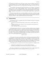
Motor spindle of a lathe
Operating data
Input power 18 kW;
maximum spindle speed 4,400 min
–1
.
Bearing selection
The bearings must be very rigid and accurately guide
the spindle in the radial and axial direction. This is
achieved by selecting as large a shaft diameter as pos-
sible and a suitable bearing arrangement. The bearings
are preloaded and have an increased precision. Also,
the specific thermal conditions found in a motor bear-
ing arrangement have to be taken into account.
Work end: 1 spindle bearing set
FAG B7024E.T.P4S.QBCL
(tandem-O-tandem arrangement )
as locating bearing
Opposite end: 1 cylindrical roller bearing
FAG N1020K.M1.SP
as floating bearing.
Bearing dimensioning
As the bearing size primarily depends on the spindle
rigidity (larger spindle diameter) bearing sizes are
obtained whose load carrying capacity is more than
adequate.
Consequently, the service life of the bearings is primari-
ly dictated by the grease service life.
Bearing clearance
The spindle bearings are mounted with a light preload.
The cylindrical roller bearing is adjusted to a radial
clearance of a few µm by axially pressing the tapered
inner ring onto the tapered shaft seat and reaches the
required zero clearance at operating temperature.
Lubrication, sealing
The bearings are lubricated for life with the rolling
bearing grease Arcanol L207V. This grease is particularly
suitable for increased temperatures and high speeds.
Approximately 35 % of the spindle bearing cavity and
approximately 20 % of the cylindrical-roller bearing
cavity is filled with grease.
Sealing is provided by a stepped labyrinth with collect-
ing grooves and drain holes. A gap-type seal protects
the cylindrical roller bearing from external contamina-
tion.
Machining tolerances
Bearing Seat Diameter Form tolerance Axial runout tolerance
tolerance (DIN ISO 1101) of abutment shoulder
Spindle bearing Shaft –5/+5 µm 1.5 µm 2.5 µm
Housing –4/+10 µm 3.5 µm 5 µm
Cylindrical roller bearing Shaft, tapered 1:12 1.5 µm 2.5 µm
Housing –15/+3 µm 3.5 µm 5 µm
14: Motor spindle bearing arrangement of a lathe
15
Vertical high-speed milling spindle
Operating data
Input power 2.6/3.14 kW;
Nominal speed 500...4,000 min
–1
.
Bearing selection
The bearings must operate reliably over the entire
speed range from 500 to 4,000 min
–1
. For example,
the spindle must be rigidly guided at 500 min
–1
under
heavy loads both in the radial and axial direction. On
the other hand, at the maximum speed of 4,000 min
–1
,
the bearing temperature must not be so high as to im-
pair accuracy.
At the milling spindle work end a spindle bearing set
FAG B7014E.T.P4S.TBTM are mounted in tandem-
O-arrangement with a medium preload. The bearing
group is preloaded with 1.9 kN by means of a nut and
a spacer sleeve.
The deep groove ball bearing FAG 6211TB.P63
guides the spindle at the drive end. To ensure clear-
ance-free operation this bearing is lightly preloaded by
means of Belleville spring washers.
Bearing dimensioning
Milling spindles must be resistant to deflection and
torsion. This requirement dictates the spindle diameter
and the bearing size. The required bearing rigidity is
obtained by the chosen bearing arrangement and pre-
load. The two angular contact ball bearings arranged at
the upper drive end accommodate the driving forces.
Machining tolerances
Seat Diameter Cylindricity Axial runout
tolerance tolerance tolerance of
(DIN ISO 1101) abutment shoulder
Shaft js4 IT1/2 IT1
Housing JS5 IT2/2 IT2
(work end)
Housing H6 IT3/2 IT3
(drive end)
Lubrication, sealing
The bearings are grease lubricated (FAG rolling bearing
grease Arcanol L74V).
A gap-type seal with oil splash ring and collecting
grooves protect the spindle bearings from contamina-
tion.
15: Bearing arrangement of a vertical high-speed milling spindle
Drive end
Work end
16
Bore grinding spindle
Operating data
Input power 1.3 kW; spindle speed 16,000 min
–1
.
The spindle is radially loaded by the grinding pressure.
The load depends on grinding wheel quality, feed and
depth of cut.
Bearing selection
Due to the high speeds required during bore grinding,
the spindle speeds must also be high. Sufficient rigidity
and accurate guidance, especially in axial direction, are
also required. The demands for high speed and high ri-
gidity can be met with spindle bearings. As the spindle
requires primarily a high radial rigidity, it is advisable
to provide bearings with a contact angle of 15° (design
C).
At the work end and at the drive end there is one spin-
dle bearing set FAG B7206C.T.P4S.DTL in tandem
arrangement each. The load is equally shared by these
O arranged tandem bearing pairs. For this purpose the
spacer rings must be identical in width and also flush
ground.
The bearings are lightly preloaded by a coil spring for
clearance-free operation under all operating condi-
tions. The preload increases the rigidity of the bearing
arrangement. It is, however, limited by the permissible
bearing temperature and varies between 300 and
500 N depending on the spindle application.
The spindle diameter, which determines the bearing
size, is based on the required rigidity.
Lubrication, sealing
Grease lubrication for high-speed bearings (FAG rolling
bearing grease Arcanol L74V). The bearings are
lubricated for life during mounting and therefore no
relubrication is required.
The high-speed bearings require the use of non-rub-
bing seals, in this case labyrinth seals.
Machining tolerances
Seat Diameter Cylindricity tolerance Axial runout tolerance
tolerance (DIN ISO 1101) of abutment shoulder
Shaft js3 IT0/2 IT0
Housing (drive end) +2/+6 µm IT1/2 IT1
Housing (work end) –1/+3 µm IT1/2 IT1
Drive end Work end
16: Bearing arrangement of a bore grinding spindle
17
External cylindrical grinding spindle
Operating data
Input power 11 kW; speed n = 7,500 min
–1
; running
accuracy: radially 3 µm, axially 1 µm.
Bearing selection
During external cylindrical grinding a high cutting ca-
pacity is required (for rough grinding) and a high stan-
dard of form and surface quality (for fine grinding). A
high degree of rigidity and running accuracy as well as
good damping and speed suitability form the main cri-
teria for the bearing arrangement. These requirements
are met by precision bearings.
Sealed universal spindle bearings with small steel balls
(HSS) are used:
– at the work end: 1 spindle bearing set
FAG HSS7020C.T.P4S.QBCL in double-
O arrangement as locating bearing
– at the drive end: 1 spindle bearing set
FAG HSS7020C.T.P4S.DBL in O arrangement as
floating bearing
Where even higher speeds have to be accommodated,
it is advisable to use sealed hybrid spindle bearings
HCS with small ceramic balls (lower centrifugal
forces).
Bearing dimensioning
The required spindle diameter or the specified outside
diameter of the quill determines the bearing size. The
contact angle of 15° is suitable for high radial rigidity.
Damping and running accuracy are improved by
arranging four bearings at the work end.
Bearing clearance
All UL universal design bearings are lightly preloaded
when mounted in O arrangement. Spacers improve the
thermal conditions and provide a larger spread at the
bearing location. To ensure that the defined bearing
preload is not altered by the spacers, the latter must be
identical in width and flush ground.
Lubrication, sealing
The sealed FAG HSS spindle bearings require no
maintenance and are lubricated for life with the FAG
rolling bearing grease Arcanol L74.
Additional sealing is provided at the grinding wheel
end by a labyrinth with defined narrow axial gaps of
0.3 ... 0.8 mm. A plain labyrinth seal is sufficient at the
drive end.
Machining tolerances
Bearing Seat Diameter Form tolerance Axial runout tolerance
tolerance (DIN ISO 1101) of abutment shoulder
Spindle bearing Shaft +3/–3 µm 1 µm 1.5 µm
(work end) Housing -3/+5 µm 2 µm 3.5 µm
Spindle bearing Shaft +3/–3 µm 1 µm 1.5 µm
(drive end) Housing +5/+13 µm 2 µm 3.5 µm
17: Bearing arrangement of an external cylindrical grinding spindle
18
Surface grinding spindle
Operating data
Grinding motor power 220 kW; maximum speed
375 min
–1
; weight of spindle, rotor and grinding spin-
dle head 30 kN; maximum grinding pressure 10 kN.
Bearing selection
The spindle is supported at the grinding spindle head
by a double-row cylindrical roller bearing FAG
NN3060ASK.M.SP. The thrust ball bearing FAG
51164MP.P5 arranged above this bearing absorbs the
thrust component of the grinding pressure. The upper
end of the spindle is fitted with a double-row cylindri-
cal roller bearing FAG NN3044ASK.M.SP and a
thrust ball bearing FAG 51260M.P6. The cylindrical
roller bearing provides radial guidance; the thrust ball
bearing carries the weight of the rotor, spindle, and
spindle head. To increase axial rigidity this bearing is
adjusted with Belleville spring washers against the
lower thrust ball bearing.
Bearing dimensioning
Rigid spindle guidance in the radial direction is en-
sured by accurately dimensioned mating parts, tight
fits of the rings, and a light preload of the cylindrical
roller bearings. The inner rings are pushed along the
tapered bearing seat until the roller-and-cage assembly
runs under a light preload (5 µm). Surface finish and
dimensional accuracy of the workpiece mainly depend
on the axial rigidity of the spindle headstock and of the
rotary table. Therefore, the rigidity of the thrust bear-
ings is especially important. To increase the rigidity, the
thrust bearings are preloaded to 40 kN by Belleville
spring washers at the upper end of the spindle. Since
the combined weight of spindle, rotor, and spindle
head is 30 kN, the lower thrust bearing is preloaded to
10 kN. Rigid, clearance-free spindle guidance also in
the axial direction is, therefore, guaranteed. The nomi-
nal rigidity is 2.5 kN/µm; the spindle deviates axially
by only 4 µm with the maximum grinding pressure of
10 kN.
Lubrication, sealing
The headstock bearings are lubricated for life with
FAG rolling bearing grease Arcanol L74V. A gap-type
seal suffices at the upper spindle end since the head-
stock is protected by a cap.
A shaft seal prevents grease from penetrating into the
motor. The lower bearings are sealed at the motor end
with a gap-type seal and at the spindle head with a gap-
type seal preceded by a labyrinth.
18: Bearing arrangement of a surface grinding spindle
19
Rotary table of a vertical lathe
Operating data
Input power 100 kW; speeds up to n = 200 min
–1
;
rotary table O.D. 2,000, 2,200 or 2,500 mm; maxi-
mum workpiece diameter 2,800 mm, maximum work-
piece height 2,700 mm, maximum workpiece weight
250 kN; maximum radial and axial runout 5 µm.
Bearing selection
The face plate bearings must provide a high running
accuracy and rigidity. As the thrust load predominates
and eccentric load application causes a great tilting
moment, a thrust ball bearing of increased precision
(main dimensions 1,250 x 1,495 x 150 mm) is in-
stalled. Radial guidance is provided by an angular con-
tact ball bearing of increased precision, FAG
7092MP.P5 (30° contact angle). Both bearings are pre-
loaded against each other with 50 kN.
The high preload guarantees a high running accuracy
while ensuring a high radial and axial moment or tilt-
ing rigidity and keeping internal heating relatively low.
By taking special measures during mounting and after
final grinding of the rotary table a maximum axial run-
out of 5 µm is obtained.
Machining tolerances
Thrust ball bearing: gearing to j5
Angular contact ball bearing: kingpin to j5/gearing to K6
Lubrication, sealing
The bearings have circulating oil lubrication.
The oil is fed directly to the various bearings through
oil feed ducts. After flowing through the bearings, the
oil passes through a filter and into an oil collecting
container from where it returns to the bearings.
The labyrinth seal prevents the oil from escaping from
the bearings and protects them from contamination.
19: Bearing arrangement of a rotary table of a vertical lathe
20
Tailstock spindle
Operating data
Maximum speed n = 3,500 min
–1
Bearing selection, dimensioning
The bearing arrangement must be particularly rigid
and have a high load carrying capacity. Other require-
ments such as precision and high-speed suitability are
met by bearings of precision design.
At the work end the high radial load is accommodated
by a double-row cylindrical roller bearing FAG
NN3014ASK.M.SP. The high axial load is accommo-
dated at the opposite end by four angular contact ball
bearings FAG 7210B.TVP.P5.UL. Three of these bear-
ings are mounted in tandem arrangement; the fourth
bearing is merely for axial counter guidance.
The maximum bearing O.D. is dictated by the size of
the quill.
Cylindrical roller bearings have a high radial load
carrying capacity, and angular contact ball bearings
with a 40° contact angle have a high axial load carrying
capacity.
Bearing clearance
The cylindrical roller bearing with a tapered bore is
preloaded with 2...3 µm by pressing the inner ring on
to the tapered shaft seat (taper 1:12).
The angular contact ball bearings of universal design
UL have a light preload in the O arrangement. The two
spacers are identical in width and exclusively serve to
provide a cavity which can accommodate the excess
grease escaping from the bearings.
Lubrication, sealing
The bearings are lubricated for life with FAG rolling
bearing grease Arcanol L135V. A labyrinth seal prevents
dirt from penetrating into the bearings.
Machining tolerances
Bearing Seat Diameter Form tolerance Axial runout tolerance
tolerance (DIN ISO 1101) of abutment shoulder
Shaft, tapered Taper 1:12 1.5 µm 2 µm
Cylindrical roller bearing
Housing –13 / +2 µm 2.5 µm 4 µm
Shaft –4 / +4 µm 1.5 µm 2 µm
Angular contact ball bearings
Housing –4 / +6 µm 2.5 µm 4 µm
20: Bearing arrangement of a tailstock spindle
21
Rough-turning lathe for round bars and pipes
Rough-turning lathes are used for particularly eco-
nomical production of bars and pipes to tolerance class
h9 with a wide range of diameters. In this process, the
stationary round stock is moved against rotating lathe
tools at a certain feed rate. In this machine four cutting
tool carriages are attached to the circumference of the
turrethead which are radially adjustable.
Operating data
Input power 75 kW; speed n = 300...3,600 min
–1
;
material O.D. 11...85 mm; feed rate 1...40 m/min.
Bearing selection
The main bearing arrangement is formed by two spin-
dle bearings FAG B7036E.T.P4S.UL and accommo-
dates the cutting forces transmitted by the four cutting
tools. The bearings are mounted in O arrangement and
preloaded with 14.5 kN (2 % of C
0
/Y
0
) by means of
springs.
C
0
static load rating
Y
0
thrust factor (static loading)
Two angular contact ball bearings FAG
71848MP.P5.UL in O arrangement accommodate the
guiding loads from the axially displaceable hollow
cone in which the four tool carriages are radially
guided and adjusted.
These bearings are also adjusted against each other
with a spring preload of 5 kN (1 % of C
0
/Y
0
).
Experience shows that with these preloads no slippage
damage results, even if the rough-turning lathe is
slowed down from 3,600 min
–1
to zero within a
second.
Machining tolerances
The inner rings of both bearings are subjected to cir-
cumferential loads and are fitted with a tolerance of
js5.The bearing seats for the outer rings are machined
to G6. The spring preload remains effective in all oper-
ating conditions as the expansion of the rotating parts
due to the effects of heat and centrifugal force do not
cause jamming of the outer rings in the housing.
Lubrication, sealing
The bearings are lubricated by oil injection lubrication
with ISO VG 32 (32 mm
2
/s at 40 °C). At 80 °C the oil
has an operating viscosity of = 8 mm
2
/s.
An elaborate labyrinth seal protects the bearings from
the ingress of cutting fluid and chips (rubbed-off parti-
cles) and from oil escape.
21: Bearing arrangement of a rough-turning lathe for round bars and pipes