The Design of Rolling Bearing Mountings Part 5 docx
Bạn đang xem bản rút gọn của tài liệu. Xem và tải ngay bản đầy đủ của tài liệu tại đây (600.92 KB, 15 trang )
Automotive differentials
Design
Spiral bevel-gear drives – with or without intersecting
axes – are now almost always used for front and rear
axle drives. Very high axial loads arise which, with
non-intersecting axes, may be several times the tangen-
tial load at the pinion. Due to the limited space and
the elevated torque values, the pinion bearings are very
heavily loaded. The pinion bearings should provide for
even meshing of pinion and crown wheel under load;
therefore, the pinion bearing arrangement should be as
rigid as possible. The pinion is either an overhung or a
straddled arrangement. The overhung arrangement is
usually fitted with two tapered roller bearings adjusted
against one another. Compact bearing arrangements
(double-row tapered roller bearings with an unsplit
cup or a cup with a flange) are common.
The crown wheel is mounted in common with the dif-
ferential. The meshing accuracy of the teeth should
vary as little as possible and mounting should, there-
fore, be provided with sufficient rigidity. The rigidity
requirements are easier to meet than with the pinion
since more mounting space is available for this applica-
tion and the axial loads are generally lower.
Bearing adjustment
Rigid pinion and crown wheel guidance is achieved by
adjusting the bearings against each other with a pre-
load. With grey-cast iron housings, thermal expansion
of the shaft increases the preload in nearly all cases af-
ter operating temperature is reached; the preload must,
however, never be such as to exceed the elastic limit of
the bearing material.
The opposite applies to aluminium housings, which
are being used more and more because of their light-
ness. So, the preload has to be selected such as to
achieve the required rigidity, but the additional bear-
ing loading must not significantly reduce the bearing
life. This is the case if the axial preload does not exceed
about half the external axial force F
a
applied.
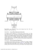
Lubrication
Differentials rely exclusively on oil lubrication. Bear-
ings and gears are lubricated with the same oil. Since
the lubricant is subjected to severe stressing in the spi-
ral gearing, hypoid oils with EP additives are used.
While the splash oil sufficiently lubricates the crown
wheel shaft bearings, which have to accommodate low-
er loads, inlets and outlets must be provided for the oil
for the pinion shaft particularly for the bearing on the
flange side. Attention should be paid to the oil flow di-
rection which is always from the small end to the large
end of the tapered rollers. The oil ducts have to be ar-
ranged and dimensioned such as to ensure that oil cir-
culates in every speed range.
The pinion shaft is normally sealed by means of radial
shaft seals, in some cases in combination with a flinger
sheet.
Bearing dimensioning
Fatigue life analysis of the bearings mounted in diffe-
rentials is based on maximum torque and correspond-
ing speed as is the case with automotive gearboxes. The
percentage times at the individual speeds are based on
experience. This information is then used to determine
the mean index of dynamic stressing. The rolling bear-
ings mounted in cars should have an average f
Lm
value
of 1 1.3.
Wear of these bearings should be minimal since diffe-
rential drives require a high guiding accuracy and as
quiet running as possible. With today's bearing di-
mensioning the service life of differential bearings is ei-
ther terminated by fatigue or wear.
A detailed calculation of the attainable life is usually
not necessary as these bearings have proved their worth
sufficiently in the automotive sector. Bearing dimen-
sioning based on a comparison calculation with the
index of dynamic stressing f
L
is sufficient.
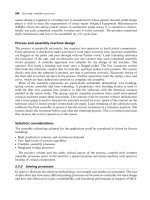
34 Final drive of a passenger car
Operating data
Maximum engine torque 160 N m at 3,000 min
–1
.
Bearing selection
Pinion shaft
The pinion shaft is fitted with FAG inch-dimensioned
tapered roller bearings mounted in O arrangement.
Dimensions: 34.925 x 72.233 x 25.4 mm (dynamic
load rating C = 65.5 kN) and 30.163 x 68.263 x
22.225 mm (C = 53 kN).
The pinion is accurately positioned relative to the
crown wheel by means of shims inserted between
housing shoulder and bearing cup. The cones are cir-
cumferentially loaded. But only the cone of the larger
bearing can be press-fitted. The cone of the smaller
bearing is slide-fitted because the bearings are adjusted
through this ring.
Crown wheel
Crown wheel and differential are mounted on the
same shaft. Fitted are two FAG inch-dimensioned
tapered roller bearings of 38.1 x 68.288 x 20 mm;
C = 39 kN.
Both bearing and gear mesh adjustment are achieved by
means of shims.
Machining tolerances
Pinion shaft: m6 (larger-size bearing)
h6 (smaller-size bearing)
housing P7
Crown wheel: hollow shaft to r6
housing to H6.
To allow the pinion to be adjusted to a certain torque
and to avoid expensive fitting work (for instance ma-
chining of a solid spacer), a thin-walled preformed
sleeve is provided between the bearing cones. The
sleeve is somewhat longer than the maximum distance
between the two bearing cones. Depending on the
width tolerance values of the bearings there will be
some elastic deformation of the sleeve (a few microns
at most).
34: Final drive of a passenger car
35–39 Automotive wheels
Differences exist between driven and non-driven
wheels for automobiles; the bearings can be either
steerable or non-steerable. Basically, all wheels must be
guided as accurately and clearance-free as possible for
driving control reasons. This is in most cases achieved
by using angular contact ball bearings or tapered roller
bearings which are adjusted against each other.
Front wheels
Where steered, non-driven front wheels are concerned,
the axle or shaft journal are relieved of torque trans-
mission and can, consequently, be given relatively
small dimensions. The tendency towards compact
wheel bearing units is encouraged by the wish for the
smallest roll radius possible as well as the pressure to
reduce weight and to simplify series mounting.
Double-row angular contact ball bearings are almost
always selected where the ratio of the mounting space
for the wheel bearings axial width to the radial cross
section height is less than 2.5. The following advan-
tages can then be felt:
– little space is required in the axial direction, a large
spread and, therefore, a high moment load carrying
capacity due to a large contact angle,
– total weight of the bearings is low,
– suitable for integration in bearing units,
– flanges can be more easily integrated – particularly
at the inner ring – than with tapered roller bearings.
Rear wheels
With non-steered rear wheels, the radial mounting
space is generally limited not only in the case of con-
ventional drum brakes but also in vehicles with disc
brakes since an extra drum brake is usually mounted at
the rear wheels as a parking brake. The actuation
mechanism is inside the drum near the axle and limits,
as a result, the maximum outside diameter of the hub.
In comparison, the axial mounting space is normally
not as restricted so the wheel bearings do not have to
be particularly short.
Today's standard bearing arrangement for such wheels,
therefore, consists of two relatively small single radial
tapered roller bearings which are mounted at a larger
distance. The bearings have small contact angles so that
the highest load rating possible is reached in a small
mounting space. The necessary spread to accommodate
tilting forces is achieved with the large bearing dis-
tance.
With the wide range of standard tapered roller bear-
ings, this simple bearing arrangement, which is inex-
pensive where solely the bearing costs are concerned,
offers diverse variations for all vehicle types and sizes.
There are, however, also some disadvantages particu-
larly with large series:
– Numerous single parts must be purchased, stored
and mounted.
– The bearings have to be greased and sealed during
mounting.
– The bearing system must be adjusted and the adjust-
ing elements secured in the correct position.
Therefore, for rear wheels there is also a tendency to
use double-row angular contact ball bearings which do
not have to be adjusted when mounting and which can
easily be integrated in bearing units.
Machining tolerances
The outer rings or cups of non-driven wheel bearings
(hub bearings) are subjected to circumferential load
(interference fit) whereas the inner rings or cones ac-
commodate point load (loose, sliding or wringing fit);
this facilitates mounting and bearing adjustment.
The the inner rings or cones of driven wheel bearings
are circumferentially loaded, and the outer rings or cups
are point-loaded; this has to be taken into account
when selecting the machining tolerances.
Non-driven front or rear wheels with two angular con-
tact ball bearings or two tapered roller bearings:
inner bearing: shaft to k6 (h6)
hub to N6, N7 (P7 for light-metal hubs)
outer bearing: axle journal to g6 j6
hub to N6, N7 (P7 for light-metal hubs)
Driven front or rear wheels with double-row angular
contact ball bearings (bearing unit):
shaft to j6 k6
hub to N6, N7 (P7 for light-metal hubs)
Bearing dimensioning
For the fatigue life calculation of wheel bearings, the
static wheel load, the dynamic tyre radius r
dyn
and its
coefficient of adhesion, as well as the speeds of the ve-
hicle in the operating conditions to be expected, are
taken into account. The loads on the individual bear-
ings or – for double-row bearings on the individual
rolling element rows – are determined with the forces
and moments calculated. The calculation results can
only be taken as reference values. Normally the ideal f
L
values for passenger cars are approximately 1.5 and for
commercial vehicles approximately 2.0.
Lubrication, sealing
Wheel bearings are almost exclusively lubricated with
grease. Bearings which have no integrated seals are nor-
mally sealed with spring-preloaded shaft seals with spe-
cial dust lips. Sealed bearings such as the double-row
angular contact ball bearings with for-life lubrication,
which are widespread in passenger cars, normally have
a combination of dust shield and seal. Experience has
shown that these seals are satisfactory if the design pro-
vides an additional gap-type seal. Collecting grooves
and baffles are also required to protect the bearings
against dust and splash water.
35 Driven and steered front wheel of a front drive passenger car
Operating data
Wheel load 4,600 N; tyre size 175/70 R14;
r
dyn
= 295 mm; maximum speed 180 km/h.
Bearing selection
The bearing arrangement is made up of a sealed dou-
ble-row FAG angular contact ball bearing.
The bearing is greased for life with FAG rolling bear-
ing grease.
The bearing arrangement of a driven and non-steered
rear wheel of a rear drive passenger car may also be de-
signed like this.
35: Passenger-car front wheel
Driven and non-steered rear wheel
36 of a rear drive passenger car
Operating data
Wheel load 4,800 N; tyre size 195/65 VR15;
r
dyn
= 315 mm; maximum speed 220 km/h.
Bearing selection
The wheel bearing arrangement consists of a double-
row FAG angular contact ball bearing which is greased
for life.
Seals and flinger rings provided on both sides protect
the bearing from contamination.
Machining tolerances
The inner rings and the outer ring of the bearing are
tightly fitted.
36: Passenger-car rear wheel
37 Driven and non-steered rear wheel of a rear drive truck
The rear wheel hubs of heavy trucks often feature a
planetary gear. This type of drive provides a relatively
high gear ratio in a limited space. As the high driving
torque is generated directly at the wheel, small diffe-
rential gears and light drive shafts are possible.
Operating data
Wheel load 100 kN; tyre size 13.00-20;
r
dyn
= 569 mm; permissible maximum speed 80 km/h.
Bearing selection
Wheel bearings
Tapered roller bearings FAG 32019XA (T4CC095 ac-
cording to DIN ISO 355) and FAG 33021 (T2DE105
according to DIN ISO 355). Since these bearings have
a particularly low section height they require only a
small radial mounting space thus allowing light-weight
constructions. The relatively large bearing width and
long rollers result in a high load carrying capacity.
The bearings are adjusted against each other in O
arrangement (large spread).
Planetary gears
The outer planet drive increases the driving torque in a
minumum space. The planet gear bearing arrangement
is of the full-complement type, i.e. it features two rows
of needle rollers. Axial guidance is provided by thrust
washers.
Machining tolerances
Direct bearing arrangement
with needle rollers: shaft to h5; housing to G6
Tapered roller bearing: shaft to j6; housing to N7
Lubrication
Common oil lubrication for planet drive and wheel
bearings. An oiltight, welded housing protects gear
and bearings against contamination.
37: Rear wheel of a truck
38 Steering king pin of a truck
A variety of steering king pin mounting arrangements
are possible. The bearing arrangement with two adjust-
ed tapered roller bearings for accommodating the axial
loads is generally used in driven truck front wheels. In
other cases the axial loads are accommodated by thrust
ball bearings or tapered roller thrust bearings. Since
the radial mounting space for king pin bearing mount-
ing arrangements is usually very limited the radial
loads (steering and guiding forces) are accommodated
by a plain bearing made of bronze and drawn cup
needle roller bearings which provide for easy steering.
Mounting with a tapered roller thrust bearing
The shock loads on the steering king pin are very high.
Therefore, the thrust bearing must have a high load
carrying capacity and be mounted with zero clearance
or preload. As the king pin performs only slight slew-
ing motions no cage is required so that the number of
rolling elements and, consequently, the load carrying
capacity can be increased.
The example features a full-complement tapered roller
thrust bearing as the thrust bearing. It has a profiled
shaft-washer raceway and a flat housing-washer race-
way. The sealed bearing is held together by a pressed
steel cap, which simplifies mounting.
The bearing is filled with special grease; it can be relu-
bricated if necessary. Openings in the sealing lip and
the elasticity of the sealing material ensure the escape
of the spent grease.
The clearance between the knuckle and the cross
member is compensated for by shims. In this way, the
thrust bearing can have zero clearance at best, which
means higher shock-type loads. Experience has shown
that this can be taken into account by means of an im-
pact factor of f
z
= 5 6, in the case of adjusted tapered
roller bearings with an impact factor of f
z
= 3 5.
The shaft washer of tapered roller thrust bearings is
located by a relatively loose fit on the steering kin pin
(g6); the housing washer has no radial guidance.
38: Steering king pin of a truck
39 Shock absorbing strut for the front axle of a car
Front axles are being equipped more and more fre-
quently with McPherson shock absorbing struts.
When driving, the coil spring and the damping unit of
the McPherson strut cause movements relative to the
body which are due to spring deflection and the degree
of lock. For comfort reasons and for easy handling,
these slewing motions are supported either by rolling
bearings or rubber elements. Deep groove ball bearings
best meet all requirements.
Bearing selection
Requirements
– Accommodation of weights and high shock loads
– Maintenance-free design
Variants
– Damping unit and spring coil rotate together –
single path solution (fig. a). The spring coil loads
and the pulsating loads from the piston rod act on
the strut bearing.
Possible bearing designs: Deep groove ball bearings
loaded axially (with cage or full-complement vari-
ants with a fracture-split outer ring) or thrust ball
bearings.
– Movements of the shock absorber's piston rod and
of coil spring are independent of each other – dual
path solution (fig. b).
Direct connection of shock absorber's piston rod to
the body via a rubber element; coil spring supported
by a special thrust ball bearing or angular contact
ball bearing (spring seat bearing).
Both variants meet all requirements concerning seal-
ing, for-life lubrication and economic efficiency.
39: Shock absorbing strut for the front axle of a car; a: single path solution; b: dual path solution
a b
40 Water pump for passenger car and truck engines
The water pump provides for circulation of the cool-
ing water in the engine. Smaller and lighter pump de-
signs are possible with ready-to-mount bearing units.
Bearing selection
The water pump bearing unit consists of the shaft and
a common outer ring with raceways for rolling-element-
and-cage assemblies. The example features one ball-
and-cage assembly and one roller-and-cage assembly
each mounted in a locating-floating bearing arrange-
ment. The roller-cage assembly is designed as the float-
ing bearing at the side that is most heavily loaded by
the belt pull. The ball-cage assembly is the locating
bearing: in addition to the radial loads it also accom-
modates the thrust of the pump impeller.
Machining tolerance, bearing clearance
The outer ring is mounted into the housing with an
R7 interference fit. The bearing clearance of the unit is
selected to allow for a small operating clearance.
Lubrication, sealing
For-life lubrication with a special rolling bearing
grease. Lip seals in the outer ring are provided on both
sides against grease escape. A spring loaded axial face
seal is fitted at the impeller end. Unavoidable water
leakage is drained to the outside through the outlet
bore.
40: Water pump bearing unit for a truck engine
41 Belt tensioner for passenger car engines
The cam shafts of many four-cycle engines are driven
with toothed belts from the crankshaft.
The belt tension necessary for quiet running is provid-
ed by an FAG bearing unit. This tensioning pulley
unit consists of a journal with integral raceways, a ball-
cage assembly and an outer ring with the plastic injec-
tion-moulded tensioning pulley.
The screw bore for fastening the tensioning pulley to
the engine housing is eccentrically located so that the
belt tension can be applied by rotating the journal.
The bearing unit is sealed on both sides and packed
with grease for life. Speed is approximately
7,000 min
–1
.
41: Belt tensioner for passenger car engines
The Design of Rolling Bearing Mountings
PDF 4/8:
Rail vehicles
Shipbuilding
Rolling Bearings
FAG OEM und Handel AG Publ. No. WL 00 200/5 EA
The Design of
Rolling Bearing Mountings
Design Examples covering
Machines, Vehicles and Equipment
Publ. No. WL 00 200/5 EA
FAG OEM und Handel AG
A company of the FAG Kugelfischer Group
Postfach 1260 · D-97419 Schweinfurt
Telephone (0 97 21) 91-0 · Telefax (0 97 21) 91 34 35
Telex 67345-0 fag d
Preface
This publication presents design examples covering
various machines, vehicles and equipment having one
thing in common: rolling bearings.
For this reason the brief texts concentrate on the roll-
ing bearing aspects of the applications. The operation
of the machine allows conclusions to be drawn about
the operating conditions which dictate the bearing
type and design, the size and arrangement, fits, lubri-
cation and sealing.
Important rolling bearing engineering terms are print-
ed in italics. At the end of this publication they are
summarized and explained in a glossary of terms, some
supplemented by illustrations.
Contents
ExampleTitle PDF
RAIL VEHICLES
Wheelsets
42Axle box roller bearings of an Intercity
train carriage . . . . . . . . . . . . . . . . . . . . . .4/8
43-44UIC axle box roller bearings for
freight cars . . . . . . . . . . . . . . . . . . . . . . . .4/8
45Axle box roller bearings of series
120's three-phase current locomotive . . .4/8
46Axle box roller bearings for an ICE
driving unit . . . . . . . . . . . . . . . . . . . . . . .4/8
47Axle box roller bearings for the Channel
tunnel's freight engine, class 92 . . . . . . .4/8
48Axle box roller bearings for an
underground train . . . . . . . . . . . . . . . . . .4/8
49Axle box roller bearings for a light rail
vehicle . . . . . . . . . . . . . . . . . . . . . . . . . . .4/8
50Axle box roller bearings according to
A.A.R. standard and modified types . . . .4/8
51Kiln trucks for sand lime brick works . . .4/8
Drives
52Universal quill drive for threephase
current locomotives of series 120 . . . . . .4/8
53Suspension bearing arrangement
for electric goods train locomotive . . . . .4/8
54Spur gear transmission for the
underground or subway . . . . . . . . . . . . .4/8
55Bevel gear transmission for city trains . . .4/8
SHIPBUILDING
Rudder shafts . . . . . . . . . . . . . . . . . . . . .4/8
56-57Spherical roller bearings as rudder
shaft bearings . . . . . . . . . . . . . . . . . . . . . .4/8
58-59Spherical roller thrust bearings as
rudder carriers . . . . . . . . . . . . . . . . . . . . .4/8
60Spade-type rudder . . . . . . . . . . . . . . . . . .4/8
Ship shafts
61-62Ship shaft bearings and stern tube
bearings . . . . . . . . . . . . . . . . . . . . . . . . . .4/8
63-64Ship shaft thrust blocks . . . . . . . . . . . . . .4/8
42 Axle box roller bearings of an Intercity train carriage
The type of axle box roller bearings presented here is
used for Intercity traffic in Europe.
The bogie frame is supported on the bearing housing
by a central coil spring, arranged above the bearings.
The wheelsets are guided by plate-type guiding arms
which are bolted on one side.
Operating data
Deadweight of the carriage plus maximum payload:
64,000 kg; two bogies, each with two wheelsets, im-
plies 4 wheelsets per car.
Resulting axle weight per wheelset: A = 64,000/4 =
16,000 kg; weight of wheelset G
R
= 1,260 kg;
acceleration due to gravity g = 9.81 m/s
2
;
supplementary factor for dynamic loads occurring dur-
ing operation f
z
= 1.3;
thrust factor for cylindrical roller bearings f
a
= 1;
number of bearings per wheelset i
R
= 4.
Thus the equivalent dynamic load per bearing is:
P = (A – G
R
)/i
R
· g · f
z
· f
a
P = (16,000 – 1,260)/4 · 9.81 · 1.3 · 1 = 46,990 N
P = 46.99 kN
Wheel diameter D
R
= 890 mm;
maximum speed v
max
= 200 km/h (possible speed
250 km/h).
Bearing selection
Cylindrical roller bearings installed as axle box roller
bearings offer important advantages:
Mounting is simple and they are easy to check and
maintain in main inspections.
Axial clearance is irrelevant for radial clearance. Cylin-
drical roller bearings are pure radial bearings, but the
lips allow the safe accommodation of all thrust loads
(guiding forces) occurring in operation.
Of all the roller bearing types cylindrical roller bear-
ings have the lowest friction. Their speed suitability is
therefore greater than in the case of other roller bear-
ings.
Cylindrical roller bearings do not, however, compen-
sate for misalignment between axle and bogie frame.
Therefore misalignment must be corrected by angular
freedom of the housing.
The same cylindrical roller bearings are used for pas-
senger cars and freight cars. This simplifies stockkeep-
ing.
Each axle box accommodates two cylindrical roller
bearings, one FAG WJ130x240TVP and one FAG
WJP130x240P.TVP.
The bearing dimensions (d x D x B) are 130 x 240 x
80 mm; the dynamic load rating C of one bearing is
540 kN.
The nominal rating life (L
h10
) is checked in kilometres
when dimensioning the axle box bearings:
L
h10km
= (C/P)
3.33
· D · π = (540/46.99)
3.33
· 890 · π =
3,397 · 2,497.6 ≈ 9.5 million kilometres.
Under these conditions the bearings are sufficiently di-
mensioned. 5 million kilometres (lower limit) applies
today as a basis for dimensioning axle box bearings for
passenger train carriages.
Machining tolerances
Bearing inner rings carry circumferential load; therefore
they are press-fitted: axle journal p6, housing H7.
Bearing clearance
The tight fit expands the bearing inner rings which re-
duces radial clearance. The air stream cools the outer
rings to a greater extent than the inner rings during
travel which leads to a further reduction in radial clear-
ance. Therefore the bearings have a radial clearance of
120 to 160 microns.
Lubrication, sealing
The bearings are lubricated with a lithium soap base
grease. Lamellar rings at the wheel side provide for ef-
fective non-rubbing sealing. A baffle plate at the cover
end keeps the grease close to the bearing. Despite the
small amount of grease (≈ 600 g) high running effi-
ciency (800,000 km and more) can be reached due to
the polyamide cages without changing the lubricant.