The Design of Rolling Bearing Mountings Part 11 pdf
Bạn đang xem bản rút gọn của tài liệu. Xem và tải ngay bản đầy đủ của tài liệu tại đây (531.54 KB, 15 trang )
92 Double toggle jaw crusher
Double toggle jaw crushers have a large mouth open-
ing. They are used, for example, as primary crushers to
prepare ballast for road building. The coarse crushing
is followed by further crushing operations until an ag-
gregate of the size and shape required, e.g. gravel or
grit, is obtained.
Operating data
Input power 103 kW; speed of eccentric shaft
n = 210 min
–1
; mouth opening 1,200 x 900 mm;
eccentric radius 28 mm.
Bearing selection, dimensioning
The pitman is fitted to the eccentric part of the hori-
zontal shaft and actuates the swing jaw through a dou-
ble toggle lever system. The inner bearings supporting
the pitman must accommodate heavy crushing loads.
The outer bearings transmit, in addition to these
loads, the flywheel weight and the circumferential
loads resulting from the drive. Due to the high loading
and the rugged operation, spherical roller bearings are
chosen. Spherical roller bearings FAG 23260K.MB are
mounted as outer bearings and FAG 23176K.MB as
inner bearings. The pitman bearing arrangement is of
the floating bearing type. The outer bearing arrange-
ment features a locating bearing at the drive side and
the floating bearing at the opposite side. With an index
of dynamic stressing f
L
≈ 4.5 the bearing arrangement is
safely dimensioned with regard to nominal rating life.
Machining tolerances
The bearings are mounted on the shaft with adapter
sleeves FAG H3260HGJ and FAG H3176HGJ, re-
spectively. The bearing seats on the shaft are machined
to h7 with a cylindricity tolerance IT5/2 (DIN ISO
1101), and the bores of housing and pitman to H7.
Lubrication, sealing
Grease lubrication with a lithium soap base grease of
penetration class 2 wit EP additives (FAG rolling bear-
ing grease Arcanol L186V). The relubrication interval
for the bearings is 2 3 months.
The bearings are sealed by multiple labyrinths. Once or
twice a week, fresh grease is injected into the laby-
rinths.
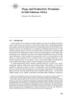
92: Bearing mounting of a double-toggle jaw crusher
Locating bearing Floating bearing
Swing jaw Eccentric shaft
Pitman
93 Hammer mill
Hammer mills are mainly used for crushing ores, coal,
and stone.
Operating data
Hourly throughput 90 120 t of iron ore; input power
280 kW; rotor speed 1,480 min
–1
, rotor weight includ-
ing hammers approximately 40 kN; bearing centre dis-
tance 2,000 mm.
Bearing selection
Due to the high loads and rugged operation, hammer
mill rotors are mounted on spherical roller bearings.
This self-aligning bearing type can compensate for mis-
alignments of the two plummer block housings, and
possible rotor deflections. Two spherical roller bearings
FAG 23228EASK.M.C3 are mounted, one acting as
the locating bearing, the other one as floating bearing.
The increased radial clearance C3 was selected because
of the high speed. The bearing inner rings heat up
more than the outer rings, causing the bearing clear-
ance to be reduced during operation.
Bearing dimensioning
The rotor weight imposes a radial load on the bearings.
Added to this are unbalanced loads and shock loads
whose magnitude can only be estimated. These loads
are introduced in the nominal rating life calculation by
multiplying the rotor weight G
R
with a supplementary
factor f
z
of 2.5 3, depending on the operating condi-
tions. The thrust loads acting on the bearings are so
small they need not be taken into account in the life
calculation.
With the dynamic load rating C = 915 kN, the speed
factor f
n
= 0.32 (n = 1,480 min
–1
) and the rotor weight
G
R
= 40 kN, the index of dynamic stressing f
L
for one
bearing:
f
L
= C · f
n
/ (0.5 · G
R
· f
z
) = 915 · 0.32 / (20 · 3) = 4.88
An f
L
value of 3.5 4.5 is usually applied to hammer
mills. Thus the bearings are adequately dimensioned
with regard to nominal rating life (L
h
approximately
100,000 h).
Bearing mounting
The bearings are mounted on the rotor shaft with
withdrawal sleeves FAG AHX3228. They are fitted
into plummer block housings MGO3228K. Both
housings (open design) are available for locating bear-
ings (design BF) and for floating bearings (design BL).
The split housings of series MGO were especially de-
veloped for mill applications. They are designed for oil
lubrication and feature particularly effective seals.
Machining tolerances
For mounting with sleeves, the shaft seats are machined
to h7, with a cylindricity tolerance IT5/2 (DIN ISO
1101). The housing bores are machined to G6. Thus
the requirement that the outer ring of the floating bear-
ing must be displaceable within the housing is met.
Lubrication, sealing
For reliable operation at high speeds, the bearings are
oil bath lubricated. Grease-packed labyrinths prevent
the ingress of foreign matter. To increase the sealing
efficiency, grease is replenished frequently. Flinger
grooves on the shaft, and oil collecting grooves in the
housing covers retain the oil within the housing.
93: Hammer mill mounting
Locating
bearing
Floating
bearing
94 Double-shaft hammer crusher
Double-shaft hammer crushers are a special type of
hammer crushers or hammer mills. They feature two
contra-rotating shafts to which the hammers are at-
tached. This type is especially suitable for crushing
large-sized material with a high hourly throughput and
optimum size reduction.
Operating data
Hourly thoughput 350 400 t of iron ore; input pow-
er 2 x 220 kW; rotor speed 395 min
–1
, rotor weight in-
cluding hammers 100 kN; bearing centre distance
2,270 mm.
Bearing selection
Due to the rugged operation, spherical roller bearings
are mounted which can compensate for misalignment
between the two plummer blocks and for shaft deflec-
tions.
Bearing dimensioning
In addition to the loads resulting from the rotor
weight, the bearings have to accommodate loads re-
sulting from imbalances and shocks. They are taken
into account by multiplying the rotor weight G
R
by
the supplementary factor f
z
= 2.5. Small thrust loads
need not be taken into account in the life calculation.
The shaft diameter at the bearing locations determines
the use of one spherical roller bearing FAG
23234EASK.M at each side. For the moderate speeds
of this application normal radial clearance CN is satis-
factory.
With the dynamic load rating C = 1,370 kN, the speed
factor f
n
= 0.476 (n = 395 min
–1
) and the rotor weight
G
R
= 100 kN, the index of dynamic stressing f
L
per bear-
ing:
f
L
= C · f
n
/(0.5 · G
R
· f
z
) = 1,370 · 0.476/(50 · 2.5) = 5.2
With this f
L
value, which corresponds to a nominal rat-
ing life L
h
of approximately 120,000 hours, the bear-
ings are very adequately dimensioned.
Bearing mounting
The bearings are mounted on the rotor shaft with
withdrawal sleeves FAG AH3234 and mounted in
FAG plummer block housings BNM3234KR.132887.
One of the plummer blocks is designed as the floating
bearing (closed on one side, design AL), the other one
as the locating bearing (continuous shaft, design BF).
The unsplit housings of series BNM were developed
especially for hammer mills and crushers. They were
designed for grease lubrication (grease valve) and
feature particularly effective seals.
Machining tolerances
The shaft seats are machined to h7, with a cylindricity
tolerance IT5/2 (DIN ISO 1101).
The housing bores are machined to H7; this allows the
outer ring of the floating bearing to be axially dis-
placed.
Lubrication, sealing
Grease lubrication with FAG rolling bearing grease
Arcanol L71V is satisfactory for the speeds in this
example. Relubrication is required at certain intervals.
A grease valve protects the bearing against over-lubrica-
tion. Due to the adverse ambient conditions a double-
passage labyrinth seal is provided. Frequent grease re-
plenishment to the labyrinths improves sealing effi-
ciency.
94: Double-shaft hammer crusher
Floating bearing Locating bearing
95 Ball tube mill
Tube mills are mostly used in the metallurgical, min-
ing and cement industries. The tube mill described is
used in an Australian gold mine for grinding aurifer-
ous minerals (grain sizes 4 30 mm) into grit by means
of grinding bodies (balls). The grain size of the materi-
al depends on the number of balls and the quantity of
added water. The grinding drum, which revolves
around its horizontal axis, is lined with chilled-cast
iron plates. Charged with the grinding stock, it is very
heavy.
Operating data
Drum: diameter 5,490 mm, length 8,700 mm; input
power 3,850 kW; speed 13.56 min
–1
; drum mass when
loaded 400 t; maximum radial load per bearing F
r
=
1,962 kN; maximum thrust load F
a
= 100 kN; bearing
distance 11,680 mm, throughput 250 t/h.
Bearing selection
Trunnion bearings
As the drum rotates, the bearings have to accommo-
date, in addition to the heavy weight, constant shock-
type loads caused by the grinding bodies. Both drum
trunnions are supported on spherical roller bearings of
series 239, 248 or 249. The bearings compensate for
static and dynamic misalignments that can be caused
by misalignments of the bearing seats (large bearing
distance) or drum deflections. In this example, spheri-
cal roller bearings with a tapered bore (K 1:30), FAG
248/1500BK30MB are mounted both as the locating
bearing at the drive end and as the floating bearing at
the feed end. The bearings are mounted on the trun-
nion with a wedge sleeve.
Drive pinion bearings
The drive pinion is supported on two spherical roller
bearings FAG 23276BK.MB with adapter sleeve
FAG H3276HG, in plummer block housings with
Taconite-seals FAG SD3276TST.
Bearing dimensioning
The dimensioning of the drum bearings is based on
half the weight of the loaded drum
(400/2 · 9.81 = 1,962 kN).
The shock loads are taken into account by a shock fac-
tor f
z
= 1.5. The required nominal rating life is
100,000 h; this corresponds to an index of dynamic
stressing f
L
= 4.9.
The equivalent dynamic load
P = f
z
· F
r
+ Y · F
a
= 2 · 1.5 · 1,962 + 4.5 · 100 =
3,393 kN
With a dynamic load rating C = 12,900 kN the index of
dynamic stressing:
f
L
= C/P · f
n
=
12,900/3,393 · 1.31 = 4.98 (L
h
> 100,000 h).
The bearings are very safely dimensioned with regard
to nominal rating life.
The bearings are mounted in split FAG plummer
block housings SZA48/1500HF (locating bearing) and
SZA48/1500HL (floating bearing). The outer rings are
tightly fitted into shell sleeves (e.g. made of grey-cast
iron) in the lower housing half. They facilitate com-
pensation of axial length variations. The sliding effect
is enhanced by grease injected into the shell
sleeve/housing joint.
Machining tolerances
The circumferentially loaded inner rings are press-fitted
on the trunnion. This is easily achieved by mounting
them hydraulically on wedge sleeves. The radial clear-
ance reduction and the radial clearance of the mounted
bearing have to be observed (see table in FAG cata-
logue WL 41 520, chapter on spherical roller bear-
ings).
The trunnions are machined to h9, with a cylindricity
tolerance IT5/2 (DIN ISO 1101); the housing bores
to H7.
Lubrication, sealing
Grease lubrication with a lithium soap base grease of
penetration class 2 with EP additives, e. g. FAG rolling
bearing grease Arcanol L186V. Continuous replenish-
ment (approx. 5 g/h per bearing) ensures adequate lu-
brication.
The bearings are sealed by multiple labyrinths. Due to
the extreme ambient conditions, the labyrinths are
preceded by dirt baffle plates and rubbing seals (V-
rings). This combination is also referred to as Taconite
sealing. The labyrinths are also continuously replen-
ished with approx. 5 g/h per labyrinth.
95: Ball tube mill mounting
96 Support roller of a rotary kiln
Rotary kilns for cement production can extend over a
length of 150 m or more. The support rollers are
spaced at about 30 m intervals.
Operating data
Kiln outside diameter 4.4 m; support roller diameter
1.6 m; support roller width 0.8 m; radial load per
support roller 2,400 kN; thrust load 700 kN. Speed
5 min
–1
; mass of support roller and housing 13 t.
Bearing selection, dimensioning
For such rotary kilns FAG offers complete assemblies
consisting of a twin housing SRL, the support roller
with axle LRW, and the bearings. In this example the
two support-roller bearings are mounted into split
plummer block housings with a common base (frame)
made of grey-cast iron. Spherical roller bearings FAG
24184B (dynamic load rating C = 6,200 kN) are
mounted in a floating bearing arrangement, i. e. the
shaft can be displaced relative to the housing by a de-
fined axial clearance.
In addition to the radial loads, the spherical roller
bearings accommodate thrust loads resulting from dis-
placements of the rotary kiln.
With an index of dynamic stressing f
L
= 4.9, correspond-
ing to a nominal rating life L
h
= 100,000 h, the bear-
ings are adequately designed.
Machining tolerances
Shaft to n6 (circumferential load on inner ring); hous-
ing bore to H7.
Lubrication, sealing
Grease lubrication with a lithium soap base grease with
EP additives (e. g. rolling bearing grease Arcanol
L186V).
At the roller side the bearings are sealed with felt strips
and grease-packed labyrinths.
96: Support roller of a rotary kiln
Vibrating machines
Vibrating screens are used for conveying and grading
bulk material. They operate in mines, quarries, stone
crushing plants and foundries, in the foodstuff and
chemical industries, and in many other preparation
and processing plants.
The main vibrating screen types are: two-bearing
screens with circle throw, two-bearing screens with
straight-line motion, and four-bearing screens.
Vibrator motors and vibrating road rollers also come
under the category of vibrating machines.
Selection of bearing type and bearing design
Rolling bearings in vibrating screens are stressed by
high, mostly shock-type loads. To compound matters,
the bearings, while rotating about their own axis, per-
form a circular, elliptical or linear vibrating motion.
This results in high radial accelerations (up to 7 g)
which additionally stress the bearings, and especially
the cages. High operating speeds, usually with inaccu-
rately aligned bearing locations, and pronounced shaft
deflections are additional requirements which are best
met by spherical roller bearings.
For these adverse operating conditions FAG spherical
roller bearings with reduced bore and outside diameter
tolerances and an increased radial clearance are used:
The FAG standard design E.T41A is used for shaft di-
ameters of 40 150 mm. The centrifugal forces of the
unloaded rollers are accommodated by two pressed-
steel, window-type cages and radially supported by a
cage guiding ring in the outer ring.
Shafts with diameters of 160 mm and more are sup-
ported on vibrating screen bearings A.MA.T41A.
These bearings have a fixed centre lip on the inner ring
and retaining lips on both sides. The split machined
brass cage is of the outer-ring riding type.
Bearing dimensioning
Vibrating screen bearings which are comparable with
field-proven bearings can be dimensioned on the basis
of the index of dynamic stressing f
L
, provided that the
boundary conditions are comparable as well. f
L
values
between 2.5 and 3 are ideal.
97 Two-bearing screen with circle throw
Operating data
Screen box weight G = 35 kN; vibration radius r =
0.003 m; speed n = 1,200 min
–1
; number of bearings
z = 2 ; acceleration due to gravity g = 9.81 m/s
2
.
Bearing dimensioning
Two-bearing screens work beyond the critical speed;
thus the common centroidal axis of the screen box and
the unbalanced load does not change during rotation.
The bearing load due to the screen box centrifugal
force is:
F
r
= 1/z · G / g · r · (π · n/30)
2
=
= 1/2 · 35 / 9.81 · 0.003 · (3.14 · 1,200/30)
2
= 84.5 kN
To allow for the unfavourable dynamic stressing, the
bearing load should be multiplied by the supplemen-
tary factor f
z
= 1.2. Thus, the equivalent dynamic load
P = f
z
· F
r
= 1.2 · 84.5 = 101.4 kN
With the index of dynamic stressing f
L
= 2.72 (L
h
=
14,000 h) and the speed factor f
n
= 0.34 (n =
1,200 min
–1
) the required dynamic load rating
C = f
L
/f
n
· P = 2.72/0.34 · 101.4 = 811.2 kN
The recommended index of dynamic stressing f
L
for
vibrating screens is 2.5 3, corresponding to a nominal
fatigue life L
h
of 11,000 to 20,000 hours. Spherical
roller bearings FAG 22324E.T41A with a dynamic
load rating of 900 kN are chosen.
Machining tolerances
The eccentric shaft features two spherical roller bear-
ings, one as the locating bearing, the other as floating
bearing. The inner rings are point loaded and mounted
with a shaft tolerance of g6 or f6. The outer rings are
circumferentially loaded and fitted tightly in the hous-
ing bore to P6.
Lubrication, sealing
Circulating oil lubrication. Mineral oils with a mini-
mum viscosity of 20 mm
2
/s at operating temperature
are recommended. The oil should contain EP additives
and anti-corrosion additives.
Outer sealing is provided by a grease-filled, replenish-
able labyrinth. A flinger ring with an oil collecting
groove prevents oil leakage. A V-ring is provided
between flinger ring and labyrinth to separate oil and
grease.
12
1 Festlager
Ll
97: Two-bearing screen with circle throw
Floating bearing
Locating bearing
98 Two-bearing screen with straight-line motion
Basically, a two-bearing screen with straight-line
motion consists of two contra-rotating, synchronous
circular throw systems.
Operating data
Screen box weight G = 33 kN; imbalance weight G
1
=
7.5 kN; amplitude r = 0.008 m; speed n = 900 min
–1
;
number of bearings z = 4 ; acceleration due to gravity
g = 9.81 m/s
2
.
Bearing dimensioning
The bearing loads of a linear motion screen vary twice
between the maximum value F
rmax
and the minimum
value F
rmin
during one revolution of the eccentric
shafts.
For calculation of these loads, the distance R between
the centres of gravity of imbalance weight and the per-
tinent bearing axes is required. Weights G and G
1
, am-
plitude of linear vibration r and distance R have the
following relationship:
G · r = G
1
· (R – r)
In this example R = 0.043 m
When the centrifugal forces act perpendicular to the
direction of vibration, the maximum radial load F
rmax
is calculated as follows:
F
rmax
= 1/z · G
1
/ g · R · (π · n/30)
2
=
= 1/4 · 7.5 / 9.81 · 0.043 · (3.14 · 900/30)
2
= 73 kN
The radial load is at its minimum (F
rmin
) when the
directions of centrifugal forces and vibration coincide.
The radial load is then
F
rmin
= 1/4 · G
1
/g · (R - r) · (π · n/30)
2
=
= 1/4 · 7.5/9.81 · 0.035 · (3.14 · 900/30)
2
= 59.4 kN
Since the radial load varies between the maximum and
minimum according to a sinusoidal pattern, the
equivalent dynamic load P with the supplementary
factor f
z
= 1.2 is thus:
P = 1.2 · (0.68 · F
rmax
+ 0.32 · F
rmin
) =
= 1.2 · (0.68 · 73 + 0.32 · 59.4) = 82.4 kN
With the index of dynamic stressing f
L
= 2.53 (L
h
=
11,000 h) selected for vibrating screens and the speed
factor f
n
= 0.372 (n = 900 min
–1
) the required dynamic
load rating
C = f
L
/f
n
· P = 2.53/0.372 · 82.4 = 560.4 kN
The spherical roller bearing FAG 22320E.T41A with a
dynamic load rating of 655 kN is chosen.
Machining tolerances
The locating bearings of the two eccentric shafts are at
the gear end, the floating bearings at the drive end. The
inner rings (point load ) are have loose fits, i. e. the
shaft is machined to g6 or f6. The outer rings are cir-
cumferentially loaded and tightly fitted in the housing
bore (P6).
Lubrication, sealing
Oil lubrication. For lubricating the spherical roller
bearings at the locating end, the oil thrown off by the
gear suffices. A flinger ring is provided for this purpose
at the opposite end. Baffle plates (A) at the housing
faces maintain an oil level reaching about the centre
point of the lowest rollers. The oil level is such that the
lower gear and the flinger ring are partly submerged.
The oil level can be checked with a sight glass.
A flinger ring and a V-ring in the labyrinth provide
sealing at the drive shaft passage.
1
2
1 Locating bearing
2 Floating bearing
A Baffle plates
B Sight glass
A
A
B
98: Bearing mounting of a two-bearing screen with straight-line motion
99 Four-bearing screen
The vibration radius of a four-bearing screen is a func-
tion of the shaft eccentricity. It is not variable; there-
fore these screens are also called rigid screens.
Operating data
Screen box weight G = 60 kN; eccentric radius r =
0.005 m; speed n = 850 min-1; number of inner bear-
ings z = 2; acceleration due to gravity g = 9.81 m/s
2
.
Bearing dimensioning
Inner bearings
For the two inner bearings of a four-bearing screen,
which are subjected to vibration, the equivalent dy-
namic load P is the same as for the two-bearing screen
with circular throw
P = 1.2 · F
r
= 1.2/z · G/g · r · (π · n/30)
2
=
= 1.2/2 · 60/9.81 · 0.005 · (3.14 · 850/30)
2
= 145.4 kN
The required dynamic load rating
C = f
L
/f
n
· P = 2.93/0.378 · 145.4 = 1,127 kN
Spherical roller bearings FAG 22328E.T41A (dynamic
load rating C = 1,220 kN) are chosen.
Outer bearings
The stationary outer bearings are only lightly loaded
since the centrifugal forces of the screen box are bal-
anced by counterweights. Generally spherical roller
bearings of series 223 are also used. The bearing size is
dictated by the shaft diameter so that the load carrying
capacity is high and fatigue life calculation unnecessary.
Since these bearings are not subjected to vibration, the
standard design with normal clearance is satisfactory.
In the example shown spherical roller bearings FAG
22320EK (dynamic load rating C = 655 kN) are
chosen.
Machining tolerances
Inner bearings
The inner bearings (a locating-floating bearing arrange-
ment ) feature point load on the inner rings: The shaft
is machined to g6 or f6. The bearings are fitted tightly
into the housing (P6).
Outer bearings
The outer bearings – also a locating-floating bearing
arrangement – are mounted on the shaft with with-
drawal sleeves. The shaft is machined to h8, the hous-
ing bore to H7.
Lubrication, sealing
Grease lubrication with a lithium soap base grease of
penetration class 2 with anti-corrosion and extreme
pressure additives. Grease supply between the roller
rows through lubricating holes in the outer rings.
Sealing is provided by grease-packed, relubricatable
labyrinths.
99: Four-bearing screen
Locating bearing
Floating bearing
Counterweight
100 Vibrator motor
The vibrations of vibrating equipment are generated
by one or several activators. An electric motor with an
imbalance rotor is an example of such an activator. It is
referred to as a "vibrator motor". Vibrator motors are
primarily mounted in machinery for making prefabri-
cated concrete parts, in vibrating screens and vibrating
chutes.
Operating data
Input power N = 0.7 kW, speed n = 3,000 min
–1
.
The bearings are loaded by the rotor weight and the
centrifugal forces resulting from the imbalances: maxi-
mum radial load on one bearing F
r
= 6.5 kN.
Bearing selection, dimensioning
Due to the high centrifugal forces, the load carrying
capacity of the deep groove ball bearings usually used
for medium-sized electric motors is not sufficient for
this application. Vibrator motors are, therefore, sup-
ported on cylindrical roller bearings. The arrangement
shown incorporates two cylindrical roller bearings
FAG NJ2306E.TVP2.C4; the dynamic load rating of
the bearings is 73.5 kN.
The adverse dynamic bearing stressing by the centrifu-
gal forces is taken into account by a supplementary
factor f
z
= 1.2. Considering this supplementary factor,
the equivalent dynamic load
P = 1.2 · F
r
= 7.8 kN.
With the speed factor f
n
= 0.26 (n = 3,000 min
–1
), the
index of dynamic stressing
f
L
= C/P · f
n
= 73.5/7.8 · 0.26 = 2.45
This f
L
value corresponds to a nominal rating life of
10,000 h. Thus the bearings are correctly dimensioned.
Machining tolerances
Shaft to k5; housing to N6.
The bearing outer rings carry circumferential load and
are, therefore, tight fits. Since the inner rings are sub-
jected to oscillating loads, it is advisable to fit them
tightly onto the shaft as well. With non-separable bear-
ings this requirement would make bearing mounting
and dismounting extremely complicated. Therefore,
separable cylindrical roller bearings of design NJ are
used.
Bearing clearance
The initial radial clearance of the bearings is reduced
by tight fits. Further radial clearance reduction results
from the different thermal expansion of inner and
outer rings in operation. Therefore, bearings of radial
clearance group C4 (i. e. radial clearance larger than
C3) are mounted.
To prevent detrimental axial preloading, the inner
rings are assembled so that an axial clearance of
0.2 0.3 mm exists between the roller sets of the two
bearings and the lips (floating bearing arrangement ).
Lubrication, sealing
Both bearings are lubricated with grease. Lithium soap
base greases of penetration class 2 with EP additives
have proved successful. Relubrication after approxi-
mately 500 hours.
Since the vibrator motor is closed at both ends, gap-
type seals with grooves are satisfactory.
100: Imbalance rotor bearings of a vibrator motor
101–103 Large capacity converters
Converters perform swinging motions and are occca-
sionally rotated up to 360˚. Bearing selection is, there-
fore, based on static load carrying capacity. Important
criteria in bearing selection are, besides a high static
load rating, the compensation of major misalignments
and length variations. Misalignment invariably results
from the large distance between the bearings and from
trunnion ring distortion and deflection. The consider-
able length variations are due to the large differences in
converter temperature as the converter is heated up
and cools down.
Bearing selection
Example 101 – showing the conventional design – fea-
tures one spherical roller bearing each as locating bear-
ing and as floating bearing. The housing of the floating
bearing is fitted with a sleeve. This simplifies axial dis-
placement of the spherical roller bearing. To minimize
the frictional resistance, the bore of the sleeve is
ground and coated with dry lubricant (molybdenum
disulphide).
For thrust load calculation a coefficient of friction of
µ = 0.1 0.15 is used.
Example 102 shows two spherical roller bearings
mounted in the housings as locating bearings. Axial dis-
placement is permitted by two collaterally arranged
linear bearings (rollers) which provide support for one
of the two housings. With this design the amount of
friction to be overcome during axial displacement is
limited to the rolling contact friction occurring in the
linear bearings (coefficient of friction µ ≈ 0.05).
Bearing dimensioning
For converters, the index of static stressing f
s
= C
0
/P
0
should be more than 2; see calculation example.
C
0
= static load rating of the bearing
P
0
= equivalent static load
Operating data
Calculation example: two spherical roller bearings and
two linear bearings (example 102).
Locating bearing: Radial load F
rF
= 5,800 kN;
Floating bearing: Radial load F
rL
= 5,300 kN;
Thrust load from drive F
a
= 800 kN and from axial
displacement 0.05 · F
rL
= 265 kN;
trunnion diameter at bearing seat 900 mm.
Two spherical roller bearings FAG 230/900K.MB
(static load rating C
0
= 26,000 kN, thrust factor
Y
0
= 3.1) are mounted.
Locating bearing
P
0
= F
rF
+ Y
0
· (F
a
+ 0.05 · F
rL
)
= 5,800 + 3.1 · (800 + 265) = 9,100 kN
Index of static stressing f
s
= 26,000 / 9,100 = 2.85
Floating bearing
P
0
= F
rL
+ Y
0
· 0.05 · F
rL
= 5,300 + 3.1 · 265 = 6,120 kN
Index of static stressing f
s
= 26,000 / 6,120 = 4.24
Both bearings are thus safely dimensioned. Five cylin-
drical rollers (80 x 120 mm) each are required for the
two linear bearings. The hardness of the guide rails
(raceways) is 59 65 HRC.
Machining tolerances
Bearings with a cylindrical bore: trunnion to m6.
Bearings with a tapered bore and hydraulic sleeve:
trunnion to h7. The trunnions are machined with a
cylindricity tolerance IT5/2 (DIN ISO 1101).
The support bores in the housing have H7 tolerance.
Tighter fits should not be used in order to prevent
bearing ovality which might otherwise result from the
split housing.
Lubrication, sealing
Converter bearings are lubricated with grease. Lithium
soap base greases of penetration class 2 with EP and
anti-corrosion additives (e. g. FAG rolling bearing
grease Arcanol L186V) are a good choice. Efficient
sealing is achieved by graphited packing rings.
Split rolling bearings
Steel mills often demand that the bearing at the con-
verter drive end are replaceable without dismounting
the drive unit. This requirement is satisfied by split
spherical roller bearings (example 103).
For cost reasons, split bearings are usually used as re-
placement bearings.