The Design of Rolling Bearing Mountings Part 15 pdf
Bạn đang xem bản rút gọn của tài liệu. Xem và tải ngay bản đầy đủ của tài liệu tại đây (542.38 KB, 13 trang )
Glossary
Contamination factor V
The contamination factor V indicates the degree of
cleanliness in the lubricating gap of rolling bearings
based on the oil cleanliness classes defined in ISO
4406.
When determining the factor a
23
and the attainable
life, V is used, together with the stress index f
s*
and the
viscosity ratio , to determine the cleanliness factor s.
V depends on the bearing cross section (D – d)/2, the
type of contact between the mating surfaces and espe-
cially the cleanliness level of the oil.
If hard particles from a defined size on are cycled in
the most heavily stressed contact area of a rolling bear-
ing, the resulting indentations in the contact surfaces
lead to premature material fatigue. The smaller the
contact area, the more damaging the effect of a particle
above a certain size when being cycled. Small bearings
with point contact are especially vulnerable.
According to today's knowledge the following cleanli-
ness scale is useful (the most important values are in
boldface):
V = 0.3 utmost cleanliness
V = 0.5 improved cleanliness
V = 1 normal cleanliness
V = 2 moderately contaminated lubricant
V = 3 heavily contaminated lubricant
Preconditions for utmost cleanliness (V = 0.3):
– bearings are greased and protected by seals or shields
against dust by the manufacturer
– grease lubrication by the user who fits the bearings
into clean housings under top cleanliness condi-
tions, lubricates them with clean grease and takes
care that dirt cannot enter the bearing during opera-
tion
– flushing the oil circulation system prior to the first
operation of the cleanly fitted bearings and taking
care that the oil cleanliness class is ensured during
the entire operating time
Guide values for V
Point contact Line contact
required guide values for required oil guide values
oil cleanliness filtration ratio cleanliness class for filtration ratio
(D-d)/2 V class according to according to according to
according to ISO 4406 ISO 4572 ISO 4406 ISO 4572
mm
0.3 11/8 
3
≥ 200 12/9 
3
≥ 200
0.5 12/9 
3
≥ 200 13/10 
3
≥ 75
≤ 12.5 1 14/11 
6
≥ 75 15/12 
6
≥ 75
2 15/12 
6
≥ 75 16/13 
12
≥ 75
3 16/13 
12
≥ 75 17/14 
25
≥ 75
0.3 12/9 
3
≥ 200 13/10 
3
≥ 75
0.5 13/10 
3
≥ 75 14/11 
6
≥ 75
> 12.5 20 1 15/12 
6
≥ 75 16/13 
12
≥ 75
2 16/13 
12
≥ 75 17/14 
25
≥ 75
3 18/14 
25
≥ 75 19/15 
25
≥ 75
0.3 13/10 
3
≥ 75 14/11 
6
≥ 75
0.5 14/11 
6
≥ 75 15/12 
6
≥ 75
> 20 35 1 16/13 
12
≥ 75 17/14 
12
≥ 75
2 17/14 
25
≥ 75 18/15 
25
≥ 75
3 19/15 
25
≥ 75 20/16 
25
≥ 75
0.3 14/11 
6
≥ 75 14/11 
6
≥ 75
0.5 15/12 
6
≥ 75 15/12 
12
≥ 75
> 35 1 17/14 
12
≥ 75 18/14 
25
≥ 75
2 18/15 
25
≥ 75 19/16 
25
≥ 75
3 20/16 
25
≥ 75 21/17 
25
≥ 75
The oil cleanliness class can be determined by means of oil samples by filter manufacturers and institutes. It is a measure of the probability of
life-reducing particles being cycled in a bearing. Suitable sampling should be observed (see e. g. DIN 51570). Today, online measuring instru-
ments are available. The cleanliness classes are reached if the entire oil volume flows through the filter within a few minutes.
To ensure a high degree of cleanliness flushing is required prior to bearing operation.
For example, a filtration ratio 
3
≥ 200 (ISO 4572) means that in the so-called multi-pass test only one of 200 particles ≥ 3 µm passes the filter.
Filters with coarser filtration ratios than 
25
≥ 75 should not be used due to the ill effect on the other components within the circulation
system.
Glossary
Preconditions for normal cleanliness (V = 1):
– good sealing adapted to the environment
– cleanliness during mounting
– oil cleanliness according to V = 1
– observing the recommended oil change intervals
Possible causes of heavy lubricant contamination
(V = 3):
– the cast housing was inadequatly cleaned
– abraded particles from components which are sub-
ject to wear enter the circulating oil system of the
machine
– foreign matter penetrates into the bearing due to
unsatisfactory sealing
– water which entered the bearing, also condensation
water, caused standstill corrosion or deterioration of
the lubricant properties
The necessary oil cleanliness class according to ISO
4406 is an objectively measurable level of the contami-
nation of a lubricant.
In accordance with the particle-counting mehod, the
number of all particles > 5 µm and all particles > 15 µm
are allocated to a certain ISO oil cleanliness classs.
For example, an oil cleanliness class 15/12 according
to ISO 4406 means that between 16,000 and 32,000
particles > 5 µm and between 2,000 and 4,000 parti-
cles > 15 µm are present per 100 ml of a fluid.
A defined filtration ratio 
x
should exist in order to
reach the oil cleanliness required.
The filtration ratio is the ratio of all particles > x µm
before passing the filter to the particles > x µm which
have passed the filter. For example, a filtration ratio

3
≥ 200 means that in the so-called multi-pass test
(ISO 4572) only one of 200 particles ≥ 3 µm passes
the filter.
Counter guidance
Angular contact bearings and single-direction thrust
bearings accommodate axial forces only in one direc-
tion. A second, symmetrically arranged bearing must
be used for "counter guidance", i.e. to accommodate
the axial forces in the other direction.
Curvature ratio
In all bearing types with a curved raceway profile the
radius of the raceway is slightly larger than that of the
rolling elements. This curvature difference in the axial
plane is defined by the curvature ratio . The curva-
ture ratio is the curvature difference between the roll-
ing element radius and the slightly larger groove
radius.
curvature ratio =
groove radius – rolling element radius
rolling element radius
Dynamic load rating C
The dynamic load rating C (see FAG catalogues) is a
factor for the load carrying capacity of a rolling bear-
ing under dynamic load. It is defined, in accordance
with DIN ISO 281, as the load a rolling bearing can
theoretically accommodate for a nominal life L of 10
6
revolutions (fatigue life).
Dynamic stressing/dynamic load
Rolling bearings are dynamically stressed when one
ring rotates relative to the other under load. The term
"dynamic" does not refer, therefore, to the effect of the
load but rather to the operating condition of the bear-
ing. The magnitude and direction of the load can re-
main constant.
When calculating the bearings, a dynamic stress is as-
sumed when the speed n amounts to at least 10 min
–1
(see Static stressing).
Endurance strength
Tests by FAG and field experience have proved that,
under the following conditions, rolling bearings can be
fail-safe:
– utmost cleanliness in the lubricating gap
(contamination factor V = 0.3)
– complete separation of the components in rolling
contact by the lubricating film (viscosity ratio ≥ 4)
– load according to stress index f
s*
≥ 8
Glossary
EP additives
Wear-reducing additives in lubricating greases and lubri-
cating oils, also referred to as extreme pressure lubri-
cants.
Equivalent dynamic load P
For dynamically loaded rolling bearings operating
under a combined load, the calculation is based on the
equivalent dynamic load. This is a radial load for radial
bearings and an axial and centrical load for axial bear-
ings, having the same effect on fatigue as the combined
load. The equivalent dynamic load P is calculated by
means of the following equation:
P = X · F
r
+ Y · F
a
[kN]
F
r
radial load [kN]
F
a
axial load [kN]
X radial factor (see FAG catalogues)
Y thrust factor (see FAG catalogues)
Equivalent static load P
0
Statically stressed rolling bearings which operate under
a combined load are calculated with the equivalent stat-
ic load. It is a radial load for radial bearings and an
axial and centric load for thrust bearings, having the
same effect with regard to permanent deformation as
the combined load.
The equivalent static load P
0
is calculated with the
formula:
P = X
0
· F
r
+ Y
0
· F
a
[kN]
F
r
radial load [kN]
F
a
axial load [kN]
X
0
radial factor (see FAG catalogues)
Y
0
thrust factor (see FAG catalogues)
Factor a
1
Generally (nominal rating life L
10
), 10 % failure prob-
ability is taken. The factor a
1
is also used for failure
probabilities between 10 % and 1 % for the calcula-
tion of the attainable life, see following table.
Failure
probability % 10 54321
Fatigue
life L
10
L
5
L
4
L
3
L
2
L
1
Factor a
1
1 0.62 0.53 0.44 0.33 0.21
Factor a
23
(life adjustment factor)
The a
23
factor is used to calculate the attainable life.
FAG use a
23
instead of the mutually dependent adjust-
ment factors for material (a
2
) and operating conditions
(a
3
) indicated in DIN ISO 281.
a
23
= a
2
· a
3
The a
23
factor takes into account effects of:
– amount of load (stress index f
s*
),
– lubricating film thickness (viscosity ratio ),
– lubricant additives (value K),
– contaminants in the lubricating gap (cleanliness
factor s),
– bearing type (value K).
The diagram on page 185 is the basis for the determi-
nation of the a
23
factor using the basic a
23II
value. The
a
23
factor is obtained from the equation a
23II
· s (s be-
ing the cleanliness factor).
The viscosity ratio = /
1
and the value K are required
for locating the basic value. The most important zone
(II) in the diagram applies to normal cleanliness
(s = 1).
The viscosity ratio is a measure of the lubricating film
development in the bearing.
operating viscosity of the lubricant, depending on the
nominal viscosity (at 40 °C) and the operating tem-
perature t (fig. 1). In the case of lubricating greases,
is the operating viscosity of the base oil.
1
rated viscosity, depending on mean bearing diameter
d
m
and operating speed n (fig. 2).
The diagram (fig. 3) for determining the basic a
23II
factor is subdivided into zones I, II and III.
Most applications in rolling bearing engineering are
covered by zone II. It applies to normal cleanliness
(contamination factor V = 1). In zone II, a
23
can be de-
termined as a function of by means of value K.
With K = 0 to 6, a
23II
is found on one of the curves in
zone II of the diagram.
With K > 6, a
23
must be expected to be in zone III. In
such a case conditions should be improved so that
zone II can be reached.
Glossary
1: Average viscosity-temperature behaviour of mineral
oils; diagram for determining the operating viscosity
3: Basic a
23II
factor for determining the factor a
23
1500
1000
680
460
320
220
150
100
68
46
32
22
15
10
120
110
100
90
80
70
60
50
40
30
20
10
4
6
8
10
20 30 40 60 100 200 300
Viscosity [mm
2
/s]
at 40 °C
Operating temperature t [°C]
Operating viscosity ν [mm
2
/s]
Mean bearing diameter d
m
=
D+d
2
[mm]
n [min
-1
]
100 000
50 000
20 000
10 000
5 000
2 000
1 000
500
200
100
50
20
10
5
2
1 000
500
200
100
50
20
10
5
3
10 20 50 100 200 500
1 000
Rated viscosity ν
1
mm
2
s
2: Rated viscosity
1
Fatigue life
The fatigue life of a rolling bearing is the operating
time from the beginning of its service until failure due
to material fatigue. The fatigue life is the upper limit
of service life.
The classical calculation method, a comparison calcu-
lation, is used to determine the nominal life L or L
h
; by
means of the refined FAG calculation process the
attainable life L
na
or L
hna
is determined (see also a
23
factor).
κ =
ν
1
ν
a
23II
20
10
5
2
1
0,5
0,2
0,1
0,05 0,1 0,2 0,5 1 2 5 10
K=0
K=1
K=2
K=3
K=4
K=5
K=6
I
II
III
Zones
I Transition to endurance strength
Precondition: Utmost cleanliness in the lubricating gap
and loads which are not too high, suitable lubricant
II Normal degree of cleanliness in the lubricating gap
(with effective additives tested in rolling bearings,
a
23
factors > 1 are possible even with < 0.4)
III Unfavourable lubricating conditions
Contaminated lubricant
Unsuitable lubricants
Limits of adjusted rating life calculation
As in the case of the former life calculation, only material fatigue
is taken into consideration as a cause of failure for the adjusted life
calculation. The calculated attainable life can only correspond to
the actual service life of the bearing when the lubricant service life
or the life limited by wear is not shorter than the fatigue life.
Fits
The tolerances for the bore and for the outside diame-
ter of rolling bearings are standardized in DIN 620
(cp. Tolerance class). The seating characteristics re-
quired for reliable bearing operation, which are depen-
dent on the operating conditions of the application,
are obtained by the correct selection of shaft and hous-
ing machining tolerances.
For this reason, the seating characteristics of the rings
are indicated by the shaft and housing tolerance sym-
bols.
Three factors should be borne in mind in the selection
of fits:
Glossary
1. Safe retention and uniform support of the bearing
rings
2. Simplicity of mounting and dismounting
3. Axial freedom of the floating bearing
The simplest and safest means of ring retention in the
circumferential direction is achieved by a tight fit.
A tight fit will support the rings evenly, a factor which
is indispensable for the full utilization of the load car-
rying capacity. Bearing rings accommodating a circum-
ferential load or an oscillating load are always fitted
tightly. Bearing rings accommodating a point load may
be fitted loosely.
The higher the load the tighter should be the interfer-
ence fit provided, particularly for shock loading. The
temperature gradient between bearing ring and mating
component should also be taken into account. Bearing
type and size also play a role in the selection of the cor-
rect fit.
Floating bearing
In a locating/floating bearing arrangement the floating
bearing compensates for axial thermal expansion.
Cylindrical roller bearings of NU and N designs, as
well as needle roller bearings, are ideal floating bear-
ings. Differences in length are compensated for in the
floating bearing itself. The bearing rings can be given
tight fits.
Non-separable bearings, such as deep groove ball bear-
ings and spherical roller bearings, can also be used as
floating bearings. In such a case one of the two bearing
rings is given a loose fit, with no axial mating surface
so that it can shift freely on its seat.
Floating bearing arrangement
A floating bearing arrangement is an economical solu-
tion where no close axial shaft guidance is required.
The design is similar to that of an adjusted bearing
arrangement. In a floating bearing arrangement, how-
ever, the shaft can shift relative to the housing by the
axial clearance s. The value s is determined depending
on the required guiding accuracy in such a way that
detrimental axial preloading of the bearings is prevent-
ed even under unfavourable thermal conditions.
In floating bearing arrangements with NJ cylindrical
roller bearings, length variations are compensated for
in the bearings. Inner and outer rings can be fitted
tightly.
Non-separable radial bearings such as deep groove ball
bearings, self-aligning ball bearings and spherical roller
bearings can also be used. One ring of each bearing –
generally the outer ring – is given a loose fit.
Grease, grease lubrication
cp. Lubricating grease
Grease service life
The grease service life is the period from start-up until
the failure of a bearing as a result of lubrication break-
down.
The grease service life is determined by the
– amount of grease
– grease type (thickener, base oil, additives)
– bearing type and size
– type and amount of loading
– speed index
– bearing temperature
Index of dynamic stressing f
L
The value recommended for dimensioning can be ex-
pressed, instead of in hours, as the index of dynamic
stressing f
L
. It is calculated from the dynamic load rat-
ing C, the equivalent dynamic load P and the speed
factor f
n
.
f
L
=
C
· f
n
P
The f
L
value to be obtained for a correctly dimen-
sioned bearing arrangement is an empirical value ob-
tained from field-proven identical or similar bearing
mountings.
The values indicated in various FAG publications take
into account not only an adequate fatigue life but also
other requirements such as low weight for light-weight
constructions, adaptation to given mating parts,
higher-than-usual peak loads, etc. The f
L
values con-
form with the latest standards resulting from technical
progress. For comparison with a field-proven bearing
mounting the calculation of stressing must, of course,
be based on the same former method.
Based on the calculated f
L
value, the nominal rating life
L
h
in hours can be determined.
s
Glossary
L
h
= 500 · f
L
p
[h]
p = 3 for ball bearings
p=
10
for roller bearings and needle roller bearings
3
Index of static stressing f
s
The index of static stressing f
s
for statically loaded bear-
ings is calculated to ensure that a bearing with an ade-
quate load carrying capacity has been selected. It is cal-
culated from the static load rating C
0
and the equiva-
lent static load P
0
.
f
s
=
C
0
P
0
The index f
s
is a safety factor against permanent defor-
mations of the contact areas between raceway and the
most heavily loaded rolling element. A high f
s
value is
required for bearings which must run smoothly and
particularly quietly. Smaller values suffice where a
moderate degree of running quietness is required. The
following values are generally recommended:
f
s
= 1.5 2.5 for a high degree
f
s
= 1 1.5 for a normal degree
f
s
= 0.7 1 for a moderate degree
K value
The K value is an auxiliary quantity needed to deter-
mine the basic a
23II
factor when calculating the attain-
able life of a bearing.
K = K
1
+ K
2
K
1
depends on the bearing type and the stress index f
s*
,
see diagram.
K
2
depends on the stress index f
s*
and the viscosity ratio
. The values in the diagram (below) apply to lubri-
cants without additives and lubricants with additives
whose effects in rolling bearings was not tested.
With K = 0 to 6, the basic a
23II
value is found on one of
the curves in zone II of diagram 3 on page 185 (cp.
factor a
23
).
Value K
1
4
3
2
1
0
0
2
46810
12
a
K
1
f
s*
b
c
d
a ball bearings
b tapered roller bearings, cylindrical roller bearings
c spherical roller bearings, spherical roller thrust bearings
3)
, cylindrical roller thrust
bearings
1), 3)
d full complement cylindrical roller bearings
1), 2)
1)
Attainable only with lubricant filtering corresponding to V < 1, otherwise
K
1
≥ 6 must be assumed.
2)
To be observed for the determination of : the friction is at least twice the value
in caged bearings. This results in higher bearing temperature.
3)
Minimum load must be observed.
Value K
2
7
6
5
4
3
2
1
0
024681012
f
s*
K
2
κ=0,25**
κ=0,3**
κ=0,35**
κ=0,4**
κ=0,7
κ=1
κ=2
κ=4
κ=0,2**
K
2
equals for 0 for lubricants with additives with a corresponding suitability proof.
** With Ϲ0.4 wear dominates unless eliminated by suitable additives.
Kinematically permissible speed
The kinematically permissible speed is indicated in the
FAG catalogues also for bearings for which – according
to DIN 732 – no thermal reference speed is defined.
Decisive criteria for the kinematically permissible
speed are e.g. the strength limit of the bearing compo-
nents or the permissible sliding velocity of rubbing
seals. The kinematically permissible speed can be
reached, for example, with
– specially designed lubrication
– bearing clearance adapted to the operating
conditions
– accurate machining of the bearing seats
– special regard to heat dissipation
Life
Cp. also Bearing life.
Glossary
Load angle
The load angle  is the angle between the resultant
applied load F and the radial plane of the bearing. It is
the resultant of the radial component F
r
and the axial
component F
a
:
tan  = F
a
/F
r
Lubricating grease
Lubricating greases are consistent mixtures of thicken-
ers and base oils. The following grease types are distin-
guished:
– metal soap base greases consisting of metal soaps as
thickeners and lubricating oils,
– non-soap greases comprising inorganic gelling
agents or organic thickeners and lubricating oils
– synthetic greases consisting of organic or inorganic
thickeners and synthetic oils.
Lubricating oil
Rolling bearings can be lubricated either with mineral
oils or synthetic oils. Today, mineral oils are most fre-
quently used.
Lubrication interval
The lubrication interval corresponds to the minimum
grease service life of standard greases (see FAG publica-
tion WL 81 115). This value is assumed if the grease
service life for the grease used is not known.
Machined/moulded cages
Machined cages of metal and textile laminated phenol-
ic resin are produced in a cutting process. They are
made from tubes of steel, light metal or textile lami-
nated phenolic resin, or cast brass rings. Cages of poly-
amide 66 (polyamide cages) are manufactured by injec-
tion moulding. Like pressed cages, they are suitable for
large-series bearings.
Machined cages of metal and textile laminated phenol-
ic resin are mainly eligible for bearings of which only
small series are produced. Large, heavily loaded bear-
ings feature machined cages for strength reasons.
Machined cages are also used where lip guidance of the
cage is required. Lip-guided cages for high-speed bear-
ings are often made of light materials, such as light
metal or textile laminated phenolic resin to minimize
the inertia forces.
Mineral oils
Crude oils and/or their liquid derivates.
Cp. also Synthetic lubricants.
β
F
F
r
F
a
Load rating
The load rating of a bearing reflects its load carrying
capacity. Every rolling bearing has a dynamic load rat-
ing (DIN ISO 281) and a static load rating (DIN ISO
76). The values are indicated in the FAG rolling bear-
ing catalogues.
Locating bearing
In a locating/floating bearing arrangement, the bearing
which guides the shaft axially in both directions is re-
ferred to as locating bearing. All bearing types which
accommodate thrust in either direction in addition to
radial loads are suitable. Angular contact ball bearing
pairs (universal design) and tapered roller bearing pairs
in X or O arrangement may also be used as locating
bearings.
Locating/floating bearing arrangement
With this bearing arrangement the locating bearing
guides the shaft axially in both directions; the floating
bearing compensates for the heat expansion differential
between shaft and housing. Shafts supported with
more than two bearings are provided with only one
locating bearing; all the other bearings must be floating
bearings.
Glossary
Modified life
The standard Norm DIN ISO 281 introduced, in ad-
dition to the nominal rating life L
10
, the modified life
L
na
to take into account, apart from the load, the
influence of the failure probability (factor a
1
), of the
material (factor a
2
) and of the operating conditions
(factor a
3
).
DIN ISO 281 indicates no figures for the factor a
23
(a
23
= a
2
· a
3
). With the FAG calculation process for the
attainable life (L
na
, L
hna
), however, operating condi-
tions can be expressed in terms of figures by the factor
a
23
.
NLGI class
Cp. Penetration.
Nominal rating life
The standardized calculation method for dynamically
stressed rolling bearings is based on material fatigue (for-
mation of pitting) as the cause of failure. The life for-
mula is:
L
10
= L =
(
C
)
p
[10
6
revolutions]
P
L
10
is the nominal rating life in millions of revolutions
which is reached or exceeded by at least 90 % of a large
group of identical bearings.
In the formula,
C dynamic load rating [kN]
P equivalent dynamic load [kN]
p life exponent
p = 3 for ball bearings
p = 10/3 for roller bearings and needle roller bearings.
Where the bearing speed is constant, the life can be ex-
pressed in hours.
L
h10
= L
h
=
L · 10
6
[h]
n · 60
n speed [min
–1
]
L
h
can also be determined by means of the index of dy-
namic stressing f
L
.
The nominal rating life L or L
h
applies to bearings
made of conventional rolling bearing steel and the usu-
al operating conditions (good lubrication, no extreme
temperatures, normal cleanliness).
The nominal rating life deviates more or less from the
really attainable life of rolling bearings. Influences such
as lubricating film thickness, cleanliness in the lubri-
cating gap, lubricant additives and bearing type are
taken into account in the adjusted rating life calculation
by the factor a
23
.
O arrangement
In an O arrangement (adjusted bearing mounting) two
angular contact bearings are mounted symmetrically in
such a way that the pressure cone apex of the left-hand
bearing points to the left and the pressure cone apex of
the right-hand bearing points to the right.
With the O arrangement one of the bearing inner
rings is adjusted. A bearing arrangement with a large
spread is obtained which can accommodate a consider-
able tilting moment even with a short bearing dis-
tance. A suitable fit must be selected to ensure dis-
placeability of the inner ring.
Oil/oil lubrication
see Lubricating oil.
Operating clearance
There is a distinction made between the radial or axial
clearance of the bearing prior to mounting and the ra-
dial or axial clearance of the mounted bearing at oper-
ating temperature (operating clearance). Due to tight
fits and temperature differences between inner and
outer ring the operating clearance is usually smaller
than the clearance of the unmounted bearing.
Operating viscosity
Kinematic viscosity of an oil at operating temperature.
The operating viscosity can be determined by means
of a viscosity-temperature diagram if the viscosities at
two temperatures are known. The operating viscosity
of mineral oils with average viscosity-temperature beha-
viour can be determined by means of diagram 1 (page
185).
For evaluating the lubricating condition the viscosity
ratio (operating viscosity /rated viscosity
1
) is formed
when calculating the attainable life.
Oscillating load
In selecting the fits for radial bearings and angular con-
tact bearings the load conditions have to be considered.
With relative oscillatory motion between the radial
Glossary
load and the ring to be fitted, conditions of "oscillat-
ing load" occur. Both bearing rings must be given a
tight fit to avoid sliding (cp. circumferential load ).
Penetration
Penetration is a measure of the consistency of a lubricat-
ing grease. Worked penetration is the penetration of a
grease sample that has been worked, under exactly de-
fined conditions, at 25 °C. Then the depth of penetra-
tion – in tenths of a millimetre – of a standard cone
into a grease-filled vessel is measured.
Penetration of common rolling bearing greases
NLGI class Worked penetration
(Penetration classes) 0.1 mm
1 310 340
2 265 295
3 220 250
4 175 205
Point load
In selecting the fits for the bearing rings of radial bear-
ings and angular contact bearings the load conditions
have to be considered. If the ring to be fitted and the
radial load are stationary relative to each other, one
point on the circumference of the ring is always sub-
jected to the maximum load. This ring is point-loaded.
Since, with point load, the risk of the ring sliding on
its seat is minor, a tight fit is not absolutely necessary.
With circumferential load or oscillating load, a tight fit
is imperative.
Polyamide cage
Moulded cages of glass fibre reinforced polyamide
PA66-GF25 are made by injection moulding and are
used in numerous large-series bearings.
Injection moulding has made it possible to realize cage
designs with an especially high load carrying capacity.
The elasticity and low weight of the cages are of advan-
tage where shock-type bearing loads, great accelera-
tions and decelerations as well as tilting of the bearing
rings relative to each other have to be accommodated.
Polyamide cages feature very good sliding and dry run-
ning properties.
Cages of glass fibre reinforced polyamide 66 can be
used at operating temperatures of up to 120 °C for
extended periods of time. In oil-lubricated bearings,
additives contained in the oil may reduce the cage life.
At increased temperatures, aged oil may also have an
impact on the cage life so that it is important to ob-
serve the oil change intervals.
Precision bearings/precision design
In addition to bearings of normal precision (tolerance
class PN), bearings of precision design (precision bear-
ings) are produced for increased demands on working
precision, speeds or quietness of running.
For these applications the tolerance classes P6, P6X,
P5, P4 and P2 were standardized. In addition, some
bearing types are also produced in the tolerance classes
P4S, SP and UP in accordance with an FAG company
standard.
Pressed cage
Pressed cages are usually made of steel, but sometimes
of brass, too. They are lighter than machined metal
cages. Since a pressed cage barely closes the gap
between inner ring and outer ring, lubricating grease
can easily penetrate into the bearing. It is stored at the
cage.
Pressure cone apex
The pressure cone apex is that point on the bearing
axis where the contact lines of an angular contact bear-
ing intersect. The contact lines are the generatrices of
the pressure cone.
In angular contact bearings the external forces act, not
at the bearing centre, but at the pressure cone apex.
This fact has to be taken into account when calculat-
ing the equivalent dynamic load P and the equivalent
static load P
0
.
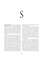
Point load
on inner
ring
Point load
on outer
ring
Weight
Imbalance
Imbalance
Weight
Stationary inner ring
Constant load direction
Stationary outer ring
Constant load direction
Rotating inner ring
Direction of load rotating
with inner ring
Rotating outer ring
Direction of load rotating
with outer ring
Glossary
Radial bearings
Radial bearings are those primarily designed to accom-
modate radial loads; they have a nominal contact angle
␣
0
≤ 45°. The dynamic load rating and the static load
rating of radial bearings refer to pure radial loads (see
Thrust bearings).
Radial clearance
The radial clearance of a bearing is the total distance
by which one bearing ring can be displaced in the
radial plane, under zero measuring load. There is a dif-
ference between the radial clearance of the unmounted
bearing and the radial operating clearance of the
mounted bearing running at operating temperature.
Radial clearance group
The radial clearance of a rolling bearing must be adapt-
ed to the conditions at the bearing location (fits, tem-
perature gradient, speed). Therefore, rolling bearings
are assembled into several radial clearance groups, each
covering a certain range of radial clearance.
The radial clearance group CN (normal) is such that
the bearing, under normal fitting and operating condi-
tions, maintains an adequate operating clearance. The
other clearance groups are:
C2 radial clearance less than normal
C3 radial clearance larger than normal
C4 radial clearance larger than C3.
Rated viscosity
1
The rated viscosity is the kinematic viscosity attributed
to a defined lubricating condition. It depends on the
speed and can be determined with diagram 2 (page
185) by means of the mean bearing diameter and the
bearing speed. The viscosity ratio (operating viscosity
/rated viscosity
1
) allows the lubricating condition to
be assessed (see also factor a
23
).
Relubrication interval
Period after which the bearings are relubricated. The
relubrication interval should be shorter than the lubri-
cation interval.
Rolling elements
This term is used collectively for balls, cylindrical roll-
ers, barrel rollers, tapered rollers or needle rollers in
rolling contact with the raceways.
Seals/Sealing
On the one hand the sealing should prevent the lubri-
cant (usually lubricating grease or lubricating oil ) from
escaping from the bearing and, on the other hand, pre-
vent contaminants from entering into the bearing. It
has a considerable influence on the service life of a bear-
ing arrangement (cp. Wear, Contamination factor V ).
A distinction is made between non-rubbing seals (e.g.
gap-type seals, labyrinth seals, shields) and rubbing
seals (e.g. radial shaft seals, V-rings, felt rings, sealing
washers).
Self-aligning bearings
Self-aligning bearings are all bearing types capable of
self-alignment during operation to compensate for mis-
alignment as well as shaft and housing deflection.
These bearings have a spherical outer ring raceway.
They are self-aligning ball bearings, barrel roller bear-
ings, spherical roller bearings and spherical roller
thrust bearings.
Thrust ball bearings with seating rings and S-type
bearings are not self-aligning bearings because they can
compensate for misalignment and deflections only dur-
ing mounting and not in operation.
Separable bearings
These are rolling bearings whose rings can be mounted
separately. This is of advantage where both bearing
rings require a tight fit.
Separable bearings include four-point bearings, cylin-
drical roller bearings, tapered roller bearings, thrust
ball bearings, cylindrical roller thrust bearings and
spherical roller thrust bearings.
Non-separable bearings include deep groove ball bear-
ings, single-row angular contact ball bearings, self-
Glossary
aligning ball bearings, barrel roller bearings and spheri-
cal roller bearings.
Service life
This is the life during which the bearing operates reli-
ably.
The fatigue life of a bearing is the upper limit of its ser-
vice life. Often this limit is not reached due to wear or
lubrication breakdown (cpl. Grease service life).
Speed factor f
n
The auxiliary quantity f
n
is used, instead of the speed
n [min
–1
], to determine the index of dynamic stressing,
f
L
.
f
n
=
p
√
33
1
/
3
n
p = 3 for ball bearings
p=
10
for roller bearings and needle roller bearings
3
Speed index n · d
m
The product from the operating speed n [min
–1
] and
the mean bearing diameter d
m
[mm] is mainly used for
selecting suitable lubricants and lubricating methods.
d
m
=
D + d [mm]
2
D bearing outside diameter [mm]
d bearing bore [mm]
Speed suitability
Generally, the maximum attainable speed of rolling
bearings is dictated by the permissible operating tem-
peratures. This limiting criterion takes into account
the thermal reference speed. It is determined on the basis
of exactly defined, uniform criteria (reference condi-
tions) in accordance with DIN 732, part 1 (draft).
In catalogue WL 41 520 "FAG Rolling Bearings" a ref-
erence is made to a method based on DIN 732, part 2,
for determining the thermally permissible operating
speed on the basis of the thermal reference speed for cases
where the operating conditions (load, oil viscosity or
permissible temperature) deviate from the reference
conditions.
The kinematically permissible speed is indicated also for
bearings for which – according to DIN 732 – no ther-
mal reference speed is defined, e. g. for bearings with
rubbing seals.
Spread
Generally, the spread of a machine component sup-
ported by two rolling bearings is the distance between
the two bearing locations. While the distance between
deep groove ball bearings etc. is measured between the
bearing centres, the spread with single-row angular
contact ball bearings and tapered roller bearings is the
distance between the pressure cone apexes.
Static load/static stressing
Static stress refers to bearings carrying a load when sta-
tionary (no relative movement between the bearing
rings).
The term "static", therefore, relates to the operation of
the bearings but not to the effects of the load. The
magnitude and direction of the load may change.
Bearings which perform slow slewing motions or ro-
tate at a low speed (n < 10 min
–1
) are calculated like
statically stressed bearings (cp. Dynamic stressing).
Static load rating C
0
The static load rating C
0
is that load acting on a sta-
tionary rolling bearing which causes, at the centre of
the contact area between the most heavily loaded roll-
ing element and the raceway, a total plastic deformation
of about 1/10,000 of the rolling element diameter. For
the normal curvature ratios this value corresponds to a
Hertzian contact pressure of about
4,000 N/mm
2
for roller bearings,
4,600 N/mm
2
for self-aligning ball bearings and
4,200 N/mm
2
for all other ball bearings.
C
0
values, see FAG rolling bearing catalogues.
Stress index f
s*
In the attainable life calculation the stress index f
s*
represents the maximum compressive stress occurring
in the rolling contact areas.
f
s*
= C
0
/P
0*
C
0
static load rating [kN]
P
0*
equivalent bearing load [kN]
P
0*
= X
0
· F
r
+ Y
0
· F
a
[kN]
F
r
dynamic radial force [kN]
F
a
dynamic axial force [kN]
X
0
radial factor (see catalogue)
Y
0
thrust factor (see catalogue)
Glossary
Synthetic lubricants/synthetic oils
Lubricating oils produced by chemical synthesis; their
properties can be adapted to meet special require-
ments: very low setting point, good V-T behaviour,
small evaporation losses, long life, high oxidation
stability.
Tandem arrangement
A tandem arrangement consists of two or more angular
contact bearings which are mounted adjacent to each
other facing in the same direction, i.e. asymmetrically.
In this way, the axial force is distributed over all bear-
ings. An even distribution is achieved with universal-
design angular contact bearings.
Thermally permissible operating speed
For applications where the loads, the oil viscosity or the
permissible temperature deviate from the reference
conditions for the thermal reference speed the thermally
permissible operating speed can be determined by
means of diagrams.
The method is described in FAG catalogue WL 41 520.
Thickener
Thickener and base oil are the constituents of lubricat-
ing greases. The most commonly used thickeners are
metal soaps (e. g. lithium, calcium) as well as polyurea,
PTFE and magnesium aluminium silicate compounds.
Thrust bearings
Bearings designed to transmit pure or predominantly
thrust loading, with a nominal contact angle ␣
0
> 45°,
are referred to as thrust bearings.
The dynamic load rating and the static load rating of
thrust bearings refer to pure thrust loads (cp. Radial
bearings).
Tolerance class
In addition to the standard tolerance (tolerance class
PN) for rolling bearings there are also the tolerance
classes P6, P6X, P5, P4 and P2 for precision bearings.
The standard of precision increases with decreasing
tolerance number (DIN 620).
In addition to the standardized tolerance classes FAG
also produces rolling bearings in tolerance classes P4S,
SP (super precision) and UP (ultra precision).
Universal design
Special design of FAG angular contact ball bearings.
The position of the ring faces relative to the raceway
bottom is so closely toleranced that the bearings can be
universally mounted without shims in O, X or tandem
arrangement.
Bearings suffixed UA are matched together in such a
way that unmounted bearing pairs in O or X arrange-
ment have a small axial clearance. Under the same con-
ditions, bearings suffixed UO feature zero axial clear-
ance, and bearings suffixed UL a light preload. If the
bearings are given tight fits the axial clearance of the
bearing pair is reduced or the preload increased.
Thermal reference speed
The thermal reference speed is a new index of the
speed suitability of rolling bearings. In the draft of
DIN 732, part 1, it is defined as the speed at which the
reference temperature of 70 °C is established. In FAG
catalogue WL 41 520 the standardized reference con-
ditions are indicated which are similar to the normal
operating conditions of the current rolling bearings
(exceptions are, for example, spindle bearings, four-
point bearings, barrel roller bearings, thrust ball bear-
ings). Contrary to the past (limiting speeds), the ther-
mal reference speed values indicated in the FAG cata-
logue WL 41 520 now apply equally to oil lubrication
and grease lubrication.
For applications where the operating conditions devi-
ate from the reference conditions, the thermally permis-
sible operating speed is determined.
In cases where the limiting criterion for the attainable
speed is not the permissible bearing temperature but,
for example, the strength of the bearing components
or the sliding velocity of rubbing seals the kinematically
permissible speed has to be used instead of the thermal
reference speed.
Glossary
Viscosity
Viscosity is the most important physical property of a
lubricating oil. It determines the load carrying capacity
of the oil film under elastohydrodynamic lubricating
conditions. Viscosity decreases with rising temperature
and vice-versa (see V-T behaviour). Therefore it is nec-
essary to specify the temperature to which any given
viscosity value applies. The nominal viscosity
40
of an
oil is its kinematic viscosity at 40 °C.
SI units for the kinematic viscosity are m
2
/s and
mm
2
/s. The formerly used unit Centistoke (cSt) corre-
sponds to the SI unit mm
2
/s. The dynamic viscosity is
the product of the kinematic viscosity and the density
of a fluid (density of mineral oils: 0.9 g/cm
3
at 15 °C).
Viscosity ratio
The viscosity ratio, being the quotient of the operating
viscosity and the rated viscosity
1
, is a measure of the
lubricating film development in a bearing, cp. factor
a
23
.
Viscosity-temperature behaviour (V-T behaviour)
The term V-T behaviour refers to the viscosity varia-
tions in lubricating oils with temperature. The V-T be-
haviour is good if the viscosity varies little with chang-
ing temperatures.
Wear
The life of rolling bearings can be terminated, apart
from fatigue, as a result of wear. The clearance of a
worn bearing gets too large.
One frequent cause of wear are foreign particles which
penetrate into a bearing due to insufficient sealing and
have an abrasive effect. Wear is also caused by starved
lubrication and when the lubricant is used up.
Therefore, wear can be considerably reduced by pro-
viding good lubrication conditions (viscosity ratio
> 2 if possible) and a good degree of cleanliness in
the rolling bearing. Where ≤ 0.4 wear will dominate
in the bearing if it is not prevented by suitable addi-
tives (EP additives).
X arrangement
In an X arrangement, two angular contact bearings are
mounted symmetrically in such a way that the pressure
cone apex of the left-hand bearing points to the right
and that of the right-hand bearing points to the left.
With an X arrangement, the bearing clearance is ob-
tained by adjusting one outer ring. This ring should be
subjected to point load because, being displaceable, it
cannot be fitted tightly (Fits). Therefore, an X arrange-
ment is provided where the outer ring is subjected to
point load or where it is easier to adjust the outer ring
than the inner ring. The effective bearing spread in an
X arrangement is less than in an O arrangement.