Handbook Properties and Selection Nonferrous Alloys and Spl Purpose Mtls (1992) WW Part 12 pptx
Bạn đang xem bản rút gọn của tài liệu. Xem và tải ngay bản đầy đủ của tài liệu tại đây (5.74 MB, 250 trang )
Molybdenum Boride Cermets. The molybdenum borides MoB and Mo
2
B have less thermal stability than the previously
discussed metal borides, but their electrical properties, hardness, and wear resistance are very good. When cemented with
nickel, these cermets have excellent corrosion resistance, for example, to dilute sulfuric acid (Ref 79). Nickel-bonded
molybdenum boride exhibits interesting behavior in two areas: First, if the composition corresponds to the compound
molybdenum-nickel boride (Mo
2
NiB
2
), if the cermet contains Mo
2
B in addition to Mo
2
NiB
2
, or if a low-melting,
intermetallic binder containing chromium boride and nickel is used, cutting tool materials can be produced from the
composition that are comparable to commercial WC tool tips for machining brass, aluminum, and cast iron (Ref 90, 91).
Second, the Mo
2
NiB
2
-type composition has thermal expansion characteristics that closely match those of the refractory
metals and a favorable melting temperature; these properties make it ideal for use as a high-temperature braze for
molybdenum and tungsten, without risk of excessive grain growth or embrittlement of the primary metal structure (Ref
79, 92). When used in rod form with shielded arc welding equipment, this cermet is suitable for brazing electronic
components in applications such as vacuum tubes and magnetrons.
Recently, a molybdenum boride cemented with an iron-base binder phase alloyed with nickel and chromium has shown
promise as a cutting tool material (Ref 93). This cermet exhibits good mechanical properties coupled with excellent wear
and corrosion resistance. In specific tool applications, such as extrusion dies for hot copper and tools for can making, this
boride cermet has performed better than cemented carbides. The role of nickel in the Mo
2
FeB
2
cermet and the effect of
varying its content up to 10 wt% in the Fe-5B-44.4Mo composition have also been investigated, mainly as part of a study
of the corrosion resistance potential of the material (Ref 94). The nickel enters only into the iron-base binder phase, which
changes with increasing nickel content from ferritic to martensitic to austenitic. The martensitic binder phase at 2.5% Ni
gives the cermet a transverse rupture strength of 2.24 GPa (325 ksi) and a hardness of 86.9 HRA.
References cited in this section
75.
L. Kaufman, E.C. Clougherty, and J.B. Berkowitz-
Mattuck, Oxidation Characteristics of Hafnium and
Zirconium Diboride, Trans. AIME, Vol 239 (No. 4), 1967, p 458-466
76.
R. Kieffer and F. Benesovsky, Hartmetalle, Springer-Verlag, 1965, p 475-479
77.
R. Steinitz, Borides Part B: Fabrication, Properties and Applications, in Modern Materials,
Vol 2,
Academic Press, 1960, p 191-224
78.
C.E. Halcombe, Jr., "Slip Casting of Zirconium Diboride," Report Y-
1819, U.S. Atomic Energy
Commission, 28 Feb 1972
79.
J.L. Everhart, New Refractory Hard Metals, Mater. Methods, Vol 40 (No. 2), Aug 1954, p 90-92
80.
J.D. Latva, Selection and Fabrication of Ceramics and Intermetallics, Met. Prog.,
Vol 82 (No. 4), Oct 1962,
p 139-144, 180, 186
81.
L. Kaufman and E.V. Cl
ougherty, Investigation of Boride Compounds for High Temperature Applications,
Metals for the Space Age, Springer-Verlag, 1965, p 722-758
82.
L. Kaufman and E.V. Clougherty, "Investigation of Boride Compounds for Very High Temperature
Applications," Report RTD-TDR-63-4096, Part 1, U.S. Air Force Materials Laboratory, Dec 1963
83.
E.V. Clougherty, R.L. Pober, and L. Kaufman, Synthesis of Oxidation Resistant Metal Diboride
Composites, Trans. AIME, Vol 242 (No. 6), 1968, p 1077-1082
84.
E.V. Clougherty et al.,
"Research and Development of Refractory Oxidation Resistant Diborides," Report
AFSC-ML-TR-68-190, U.S. Air Force Materials Laboratory, Part 1, Oct 1968; Part 2, Vol 1-7, Nov 1969-
June 1970; Part 3, May 1970
85.
H.M. Greenhouse, R.F. Stoops, and T.S. Shevlin, A New Carbide-Base Cermet Containing TiC, TiB
2
and
CoSi, J. Am. Ceram. Soc., Vol 37 (No. 5), 1954, p 203-206
86.
E.T. Montgomery et al.,
"Preliminary Microscopic Studies of Cermets at High Temperatures," U.S. Air
Force Report WADC-TR-54-33, Part 1, April 1955, Part 2, Feb 1956
87.
Gradient Ceramic/Metals Made by Advanced Methods, Adv. Mater. Proc., Vol 132 (No. 4), Oct 1987, p 20
88.
S.J. Sindeband, Properties of Chromium Boride and Sintered Chromium Boride, Trans. AIME,
Vol 185,
Feb 1949, p 198-202
89.
I. Binder and D. Moskowitz, "Cemented Borides," PB 121346, Office of Technical Services, U.S.
Department of Commerce, 1954-1955
90.
R. Steinitz and I. Binder, New Ternary Boride Compounds, Powder Metall. Bull.,
Vol 6 (No. 4), Feb 1953,
p 123-125
91.
I. Binder and A. Roth, An Evaluation of Molybdenum Borides as Cutting Tools, Powder Metall. Bull.,
Vol
6 (No. 5), May 1953, p 154-162
92.
A. Blum and W. Ivanick, Recent Developments in the Application of Transition Metal Borides,
Powder
Metall. Bull., Vol 7 (No. 3-6), April 1956
93.
K. Takagi, S. Ohira, T. Ide, T. Watanabe, and Y. Kondo, New P/M Iron-
Containing Multiple Boride Base
Hard Alloy, in Modern Developments in Powder Metallurgy,
Vol 16, Metal Powder Industries Federation,
1985, p 153-166
94.
K. Takagi, M. Komai, T. Ide, T. Watanabe, and Y. Kondo, Effect of Ni on the Mechanical Properties of Fe,
Mo Boride Hard Alloys, Int. J. Powder Metall., Vol 23 (No. 3), 1987, p 157-161
Other Refractory Cermets
The nitrides, carbonitrides, and silicides of certain transition metals have gained importance for specific uses in operations
involving high temperatures. The main mode of application for these refractory cermets, however, is in the form of
coatings, such as TiN and TiC-TiN in various ratios for high-speed cutting tools or MoSi
2
for surface protection of
molybdenum against high-temperature oxidation. In a very few cases, these compounds are used as solids, either in the
pure state or cemented with a lower-melting metallic phase.
Carbonitride- and Nitride-Based Cermets. Titanium nitrides and titanium carbonitrides have been found suitable for use as
the hard phase for tool materials (Ref 95). The best binder is an alloy of 70Ni-30Mo, and optimum hardness, in the 1000
to 2000 HV range, is obtained with 10 wt% binder. The hardness increases progressively with the TiC component of the
solid solution. The same trend prevails for the hardness of a cermet containing 14 wt% binder: The values increase from
about 1400 to 1900 HV for the straight cemented TiC composition. Transverse rupture strength does not follow any trend;
the best values reach about 1300 MPa (188 ksi) for a 10 wt% binder composition with a 72-to-18 TiN-TiC ratio and a 14
wt% binder material with a 69-to-17 TiN-TiC ratio. This compares with 1070 and 1275 MPa (155 ksi and 185 ksi),
respectively, for the straight TiC cermets with 10 and 14 wt% binder. The hardness of titanium nitride alone cemented
with 10% of the 70Ni-30Mo alloy has a hardness level of about 1050 HV and a transverse rupture strength of about 785
MPa (115 ksi). Titanium carbonitride cermets for tool applications are discussed in greater detail in the section "Titanium
Carbonitride Cermets" in this article.
Combinations of nitrides and borides, with or without metallic binder, can also be fabricated into tools. A mixture of 60
wt% tantalum nitride (TaN) and 40 wt% ZrB
2
has been hot pressed into tool bits that have performed very well at very
high cutting speeds (Ref 96).
Nitride products based on the metalloids boron and silicon, like their carbide counterparts, have gained some significant
commercial uses since their early development in the 1950s and 1970s, respectively. The normal hexagonal crystal lattice
of boron nitride (BN) can be converted to a cubic crystal form by reacting boron powder with nitrogen at a minimum
temperature of 1650 °C (3000 °F) while simultaneously applying pressure in excess of 7000 MPa (1000 ksi) with the aid
of special press tools adopted from the manufacture of synthetic diamond. The product is extremely hard and is
considered to be one of the best electrical insulators known, especially at high temperatures up to about two-thirds of its
melting point, that is, in the vicinity of 2730 °C (4950 °F) (Ref 45, 97).
Cermets exhibiting excellent cutting performance have been achieved by bonding carefully graded particles of the
superhard cubic boron nitride with cobalt or similar hard metal binders. Hot pressing is the preferred method of powder
consolidation, and tool bits made in this manner outperform tungsten carbide tips by a factor of two-to-one and better
(Ref 98).
The nitride of silicon and its combination with different oxides, notably Al
2
O
3
(known as the SiAlONs), as well as the
different silicon ceramics based on silicon carbide, belong to the increasingly important new class of refractory materials
known as structural ceramics. Additives of these cermets are nonmetallic and serve mainly to control the sintering
mechanism. They do not contribute to a strengthening of the hard particle structure in the sense of a metallic binder. In
fact, they cause a weakening of the grain-boundary network at high temperature in many systems. Therefore, these silicon
ceramics are considered to lie outside the material classification for cermets.
Silicide Cermets. The metallic silicides have found commercial use only in isolated instances. This is due chiefly to the
extreme brittleness of these compounds and to the concomitant problems encountered when they are fabricated into solid
objects. Because of its outstanding high-temperature oxidation resistance, and its favorable coefficients of thermal
expansion and electrical resistance, molybdenum disilicide (MoSi
2
) is an important material for heating elements. Poor
resistance to mechanical and thermal shock is the major deficiency of molybdenum disilicide and limits the applications
of this material to simple cylindrical or rectangular shapes. Additions of metallic elements to remedy this handicap have
been only partially successful, and MoSi
2
cermets with nickel, cobalt, and platinum binder metals are still too brittle for
fabrication into complex shapes (Ref 99). High-temperature bearings have been made experimentally by infiltrating
molten silver into hard matrices containing MoSi
2
, tungsten disilicide (WSi
2
), or vanadium disilicide (VSi
2
); these
bearings have shown good antifriction behavior against steels at elevated temperatures (Ref 100).
Graphite- and Diamond-Containing Cermets. Materials that contain a combination of carbon in the form of graphite or
diamond with metals constitute a border region for cermets and are usually not designated as such. However, because the
carbon and metallic components are most often intimately mixed and uniformly distributed in the microstructure, they are
pertinent to this discussion.
Graphite-metal combinations for electrical contact applications basically fall into two types of materials. For metallic
brushes used in motors and generators, the metallic phase consists of copper or bronze; in the case of sliding contacts
involving relatively low rubbing speeds and light contact pressure, the metallic phase is silver. In brushes, the graphite
particle content may spread over a wider range, from 5 to 70 wt%. A typical binary composition contains 70% Cu and
30% graphite. To improve wear and bearing properties, many brushes also contain up to 10% Sn and/or Pb and up to 12%
Zn (Ref 101). The graphite content in the silver contact composition generally ranges between 2 and 50 wt%.
Graphite-containing metallic friction materials for brake linings and clutch facings have a predominantly metallic matrix
to utilize a high thermal conductivity. This property permits rapid energy absorption, making this type of material suitable
for service under a more severe wear and temperature environment than that which is possible for organic, resin-bonded
asbestos friction elements. The most important contribution of a cermet-type lining material in aircraft brakes probably
has been an increased energy capacity without additional weight or the use of a larger unit (Ref 102). The friction
coefficient of these cermets is tailored to the requirements of the particular application, principally by varying the ratio of
a friction-producing ceramic to the graphite, which acts as a solid lubricant. The metallic matrix phase is essentially a
bearing alloy containing 60 to 75 wt% Cu and 5 to 10% each of tin, lead, zinc, and/or iron. Graphite content falls within
the 5 to 10% range, and the ceramic, mainly SiO
2
with the possibility of some Al
2
O
3
additions, amounts to 2 to 7% (Ref
103).
Cermets composed of diamond, varying in size from coarse splinters to fine dust inside a metal matrix, are used for
grinding, lapping, sawing, cutting, dressing, and trueing tools. The size of the diamond is important for the efficiency of
the tool; although finish improves as the grain or grit size becomes finer, the cutting speed is slower. For dressing tools, 5
to 35 diamond splinters are embedded per carat with a size of approximately 1 to 2.5 mm (0.04 to 0.1 in.). For rough
grinding, the grit size is in the range of 0.15 to 0.5 mm (0.006 to 0.02 in,); for fine polishing, it falls between 0.05 and
0.15 mm (0.002 and 0.006 in.). Even finer diamond powder is used in combination with tungsten carbide for specialized
applications such as polishing plane surfaces of hard metal tools or finishing the rolls for Sendzimir-type mills. Typical
compositions of these tools contain 12 to 16 wt% diamond dust embedded in a tungsten carbide matrix cemented with
13% Co (Ref 104).
Other metallic bonding substances are based on copper, iron, nickel, molybdenum, or tungsten. Examples for copper
matrices are bronzes with 10 to 20% Sn or 2 to 4% Be, which can be strengthened by precipitation hardening, and a
47Cu-47Ag-6Co alloy. Bonding metals suitable for somewhat higher-temperature service include iron-nickel, iron-nickel-
chromium, and iron-tin-antimony-lead alloys; Permalloy; and nickel alloys containing 2 to 8% Be. Refractory metal-base
matrices are alloys of the molybdenum-copper, molybdenum-cobalt, or tungsten-nickel-copper types and tungsten-nickel-
iron heavy alloys (Ref 104). In general, the bond materials must be selected with consideration of lowest possible
processing temperatures to avoid the possible transformation of the diamond to graphite.
References cited in this section
45. B.C. Weber and M.A. Schwartz, Container Materials for Melting Reactive Metals, in Cermets,
Reinhold,
1960, p 154-158
95. R. Kieffer, P. Ettmayer, and M. Freudhofmeier, About Nitrides and Carbonitrides and Nitride-
Based
Cemented Hard Alloys, in Modern Developments in Powder Metallurgy,
Vol 5, Plenum Press, 1971, p
201-214
96. F.C. Holtz and N.M. Parikh, Developments in Cutting Tool Materials, Eng. Dig.,
Vol 28 (No. 1), 1967, p
73, 75, 99
97. Borazon Man Made Material Is Hard as Diamond, Mater. Methods, Vol 45 (No. 5), 1957, p 194, 196
98. N.J. Pipkin, D.C. Roberts, and W.I. Wilson, Amborite
A Remarkable New Cutting Material from De
Beers, Ind. Diamond Rev., June 1980, p 203-206
99. R. Kieffer and F. Benesovsky, Hartmetalle, Springer-Verlag, 1965, p 487-489
100.
R.H. Baskey, An Investigation of Seal Materials for High Temperature Applications, Trans.
Am. Soc. Lub.
Eng., Vol 3 (No. 1), 1960, p 116-123
101.
F.V. Lenel, Powder Metallurgy, Metal Powder Industries Federation, 1980, p 556
102.
R.H. Heron, Friction Materials A New Field for Ceramics and Cermets, Ceram. Bull.,
Vol 34 (No. 12),
1955, p 295-298
103.
F.V. Lenel, Powder Metallurgy, Metal Powder Industries Federation, 1980, p 485
104.
C.G. Goetzel, Treatise on Powder Metallurgy, Vol 2, Interscience, 1950, p 171-174
Superabrasives and Ultrahard Tool Materials
T.J. Clark, G.E. Superabrasives; and R.C. DeVries, G.E. Corporate Research and Development Center (Retired)
Introduction
THE PRINCIPAL superhard materials are found as phases in the boron-carbon-nitrogen-silicon family of elements (Fig.
1). Of these, the superhard materials of commercial interest include silicon nitride (Si
3
N
4
), silicon carbide (SiC), boron
carbide (B
4
C), diamond, and cubic boron nitride (CBN). Silicon nitride provides the base composition for the important
category of SiAION ceramics, which are used in structural applications (see the article "Structural Ceramics" in this
Volume) and as high-speed cutting tool materials (see the article "Ceramics" in Machining, Volume 16 of ASM
Handbook, formerly 9th Edition Metals Handbook).
Fig. 1 The carbon-boron-nitrogen-
silicon composition tetrahedron showing the principal known superhard materials: the diamond form of
carbon, cubic BN, SiC, and B
4
C. Polycrystalline aggregates of diamond and SiC as well as Si
3
N
4
are also commercially available.
The carbides of the metalloids boron and silicon (B
4
C and SiC in Fig. 1) are also of considerable industrial significance
and enjoy such diverse applications as superhard tools and electrical resistor heating elements. These compounds are
processed and used both with or without metallic binder phases. When these two metalloid carbides are used without a
metallic binder phase, the resultant material most likely falls within the material group of ceramics. If silicon carbide
(SiC) and boron carbide (B
4
C) are used with a metallic binder phase, then the resultant material is considered a cermet
(see the article "Cermets" in this Volume).
This article focuses exclusively on the superhard materials consisting of either diamond or CBN. The other commercially
significant materials in Fig. 1 are discussed in the above-mentioned articles of ASM Handbook. Additional information on
the superhard nitrides and carbides can be found in Ref 1 and 2. Information on possible new hard materials is available
in Ref 3.
The focus of this article is further restricted to synthesized diamond and CBN. The latter does not occur in nature, and the
former commands 90% of the industrial diamond market. These materials will be treated in terms of the forms in common
use: diamond or CBN grains (looser or bonded) and sintered polycrystalline diamond or CBN tools.
References
1.
Ceram. Bull., Vol 67 (No. 6), 1988
2.
P. Schwarzkopf and R. Kieffer, Refractory Hard Materials, Macmillan, 1953
3.
A.Y. Liu and M.L. Cohen, Prediction of New Low Compressibility Solids, Science, Vol 245, 1989, p 841-842
Synthesis of Diamond and Cubic Boron Nitride
The basic objective in the synthesis of diamond and CBN is to transform a crystal structure from a soft hexagonal form to
a hard cubic form. In the case of carbon, for example, hexagonal carbon (graphite) would be transformed into cubic
carbon (diamond). Synthetic CBN and diamond are produced either as crystalline grains or as sintered polycrystalline
products.
The synthesis of CBN or diamond grit can be achieved by static high-pressure high-temperature (HPHT) processing or by
dynamic (explosive) techniques. The HPHT method, despite high equipment investment costs, is the predominant
technique for producing synthetic diamond and CBN. In addition, diamond is also synthesized under metastable
conditions (see the section "Low-Pressure Synthesis of Superhard Coatings" in this article).
High-Pressure High-Temperature Synthesis. The bulk of synthetic CBN and diamond is made by subjecting hexagonal carbon
or boron nitride to high temperatures and high pressures with large special-purpose presses or with the commonly used
mechanical device known as the uniaxial belt (Ref 4). By the simultaneous application of heat and pressure, hexagonal
carbon or boron nitride can be transformed into a hard cubic form. This requires strenuous pressures and temperatures, as
illustrated in the graphite-diamond and hexagonal BN-cubic carbon nitride equilibrium diagrams (Fig. 2, 3).
Fig. 2 Pressure-
temperature diagram showing the stability regions of diamond and graphite and the role of the solvent/catalyst in lowering
the synthesis conditions
Fig. 3 Equilibrium diagram for HBN and CBN
It is possible to directly convert graphite to diamond, but very high pressures are required, and the properties of the
resultant product are difficult to control. In commercial practice, the required conditions for diamond synthesis can be
reduced by the use of solvent/catalysts such as nickel, iron, cobalt, and manganese or alloys of these metals (Ref 5, 6).
Figure 4 shows an example of a metal-carbon system at 5.7 GPa (57 kb), where a stable diamond plus liquid region exists.
Even with solvent/catalysts it is necessary to simultaneously sustain a pressure of about 5 GPa (50 kb)and a temperature
of about 1500 °C (2700 °F), for periods ranging from minutes to hours, to make the variety of products in common use
today.
Fig. 4 Nickel-
carbon system at 5.7 GPa (57 kb) showing the stability regions of diamond (d) and graphite (g) in equilibrium with liquid (l +
d, l + g). a, austenite. Source: Ref 7
Conditions are similar for the synthesis of CBN, but the reactants are usually alkali, alkaline earth metals, or compounds.
Cubic boron nitride can be grown from a variety of solvent/catalysts, including metal systems similar to those used for
diamond synthesis (Ref 8). Because the pressure-temperature conditions for the conversion of hexagonal boron nitride
(HBN) to CBN are less severe than those for the conversion of graphite to diamond, some sintered polycrystalline
products are synthesized by the direct process under static conditions; however, most commercial monocrystalline CBN is
made by a solvent/catalyst process.
Explosive Shock Synthesis. The direct conversion of graphite to diamond, or HBN to CBN, can be done on a commercial
scale using explosive shock techniques (Ref 9). The process is relatively simple but produces only fine-grain materials,
which are principally used as polishing powders or as possible source materials for sintering into polycrystalline products.
Low-Pressure Synthesis of Superhard Coatings. The history of diamond synthesis under metastable conditions (plasma-
assisted, chemical vapor deposition, or physical vapor deposition coating processes) goes back at least to the late 1950s
and perhaps even earlier. The efforts of Russian (Ref 10) and Japanese (Ref 11) scientists in the period from 1975 to 1985
made this technique feasible for limited commercial applications. The potential exists to make films or sheets of
polycrystalline and single-crystal diamond at temperatures of about 900 °C (1650 °F) and at pressures of less than 1
atmosphere (0.1 MPa). A limited amount of information exists (Ref 12) on grinding or machining applications of these
materials. Some films have been made for x-ray windows, speaker diaphragms, and wear surfaces.
Synthesis of Polycrystalline Diamond and Polycrystalline Cubic Boron Nitride. It is possible also to produce polycrystalline
diamond (PCD) or polycrystalline cubic boron nitride (PCBN) by sintering (or binding) many individual crystals of
diamond or CBN together to produce a larger polycrystalline mass. It is commercial practice to enhance the rate of
sintering by the addition of a metal second phase (Ref 13). In addition, the whole mass must again be maintained in the
cubic region of the respective temperature-pressure phase diagram to prevent the hard cubic crystals from reverting to the
soft hexagonal form. By such high-temperature high-pressure sintering techniques, it is possible to obtain a mass of
diamond or CBN in which randomly oriented crystals are combined to produce a large isotropic mass.
An immense range of polycrystalline products can be made of diamond or CBN. Changes in grain size, the second phase
employed, the degree of sintering, the particle size distribution, and the presence or absence of inert ceramic, metallic, or
non-metallic fillers are examples of factors that have profound effects on the mechanical, physical, and thermal properties
of the final product. By careful formulation it is possible to tailor material properties for particular applications.
References cited in this section
4. H.T. Hall, Ultra-High-Pressure, High-Temperature Apparatus: The "Belt," Rev. Sci. Instrum.,
Vol 31 (No.
2), 1980, p 125-131
5.
H.P. Bovenkerk, F.P. Bundy, H.T. Hall, H.M. Strong, and R.H. Wentorf, Jr., Preparation of Diamond,
Nature, Vol 184, 1959, p 1094-1098
6. R.J. Wedlake, Technology of Diamond Growth, in The Properties of Diamond,
J. Field, Ed., Academic
Press, 1979
7. H.M. Strong and R.E. Hanneman, Crystallization of Diamond and Graphite, J. Chem. Phys.,
Vol 46, 1967,
p 3668-3676
8. R.C. DeVries and J.F. Fleischer, Phase Equilibria Pertinent to the Growth of Cubic Boron Nitride,
J. Cryst.
Growth, Vol 13/14, 1972, p 88-92
9.
P.S. DeCarli, Method of Making Diamond, U.S. Patent 3,238,019, March 1966; and P.S. DeCarli and J.C.
Jamieson, Formation of Diamond by Explosive Shock, Science, Vol 133, 1966, p 1821-1822
10.
B.V. Spitsyn, L.L. Bouilov, and B.V. Derjaguin, Vapor Growth of Diamond on Diamond and Other
Surfaces, J. Cryst. Growth, Vol 52, 1981, p 219-226
11.
S. Matsumoto, Y. Sato, M. Tsutsumi, and N. Setaka, Growth of Diamond Particles from Methane-
Hydrogen
Gas, J. Mater. Sci., Vol 17, 1982, p 3106-3112
12.
B. Lux and R. Haubner, Low Pressure Synthesis of Superhard Coatings, Int. J. Refract. Met. Hard Mater.,
Vol 9, 1989, p 158-174
13.
R.H. Wentorf, Jr. and W.A. Rocco, Diamond Tools for Machining, U.S. Patent 3,745,623, July 1973
Properties of Diamond
The crystal structure of diamond and the lattice structure of graphite are shown in Fig. 5. The conversion from graphite to
diamond is accompanied by a 26% decrease in volume. For diamond, all the lattice sites are occupied nominally by
carbon, but boron and nitrogen can be substituted for carbon in amounts in the parts-per-million range. Synthesized
diamond usually has metal, metal carbide, and graphite inclusions; however, some of the metal may be on defect or
interstitial sites and thus may not be visible.
Fig. 5
Arrangement of carbon atoms in diamond and graphite. The arrows indicate the transformation of graphite to diamond at HPHT
conditions and the reverse transformation at low pressures and high temperatures (LPHT).
Diamond oxidizes in air above about 600 °C (1100 °F) and back converts into a poorly graphitized form (as indicated by
the reverse arrow in Fig. 5) upon heating in the absence of air. The reaction rate for the transformation back into graphite
is dependent on conditions, but it is a significant factor at temperatures about 750 °C (1400 °F) in many practical
applications. These phenomena impose critical limitations on the use and fabrication of bonded-abrasive tools.
Diamond is chemically inert to inorganic acids, but upon heating it reacts readily with carbide-forming elements such as
iron, nickel, cobalt, tantalum, tungsten, titanium, vanadium, boron, chromium, zirconium, and hafnium. Controlled
reactivity is important in forming metal bonds, but that same reactivity can limit the use of diamonds in cutting and
grinding applications.
The thermal conductivity of some near-perfect diamond crystals can be as high as 5× that of copper at room temperature.
Less-perfect materials still have a high conductivity, and this has to be taken into consideration before use in many
applications. In terms of electrical conductivity, diamond is an electrical insulator unless doped with boron or, as in some
commercial materials, mixed with a metal phase.
Diamond is the hardest practical material known (Table 1). The hardness of single-crystal diamond varies as a function of
orientation, but this is important only in single-point tools and in the polishing of gemstones, diamond microtome blades,
and diamond surgical knives.
Table 1 Properties of selected hard materials
Density Compressive
strength
Coefficient of thermal
expansion
Thermal
conductivity
g/cm
3
lb/in.
3
Hardness,
HK
GPa
10
6
psi
mm/mm/°C ×
10
-6
in./in./°F ×
10
-6
W/m ·
K
cal/°C · cm
· s
Diamond (C) 3.52 0.127 7000-10000 10 1.5 4.8 2.7 2100 5.0
Cubic boron nitride 3.48 0.126 4500 7 1 5.6 3.1 1400 3.3
Silicon carbide (SiC) 3.21 0.116 2700 1.3 0.19 4.5 2.5 42 0.10
Alumina oxide (Al
2
O
3
) 3.92 0.142 2100 3 0.435 8.6 4.8 33 0.08
Tungsten carbide (WC-
Co, 6%)
15.0 0.542 1700 5.4 0.78 4.5 2.5 105 0.25
Although hard, diamond is a brittle material and breaks on impact, primarily by cleavage on the four (111) planes.
Toughness or friability can be varied considerably for synthesized grains. Thus, it is possible to make a very friable
material for some grinding operations and a very tough material for stonecutting. The presence of defects and second
phases can be manipulated to influence the fracture properties of synthesized diamond. This control is not available from
most natural stones.
Most natural diamonds are essentially octahedral in shape as grown. Irregularly shaped fragments can be obtained by
crushing and selection. Synthesized diamond can be reproducibly grown as cubes, cubooctahedrons, and octahedrons
(Fig. 6). The cubooctahedral shapes are generally preferred for stone sawing, but they are not always appropriate for
grinding.
Fig. 6
Shapes of synthesized diamond abrasive grains. Varying proportions of cube (100) and octahedral faces (111) predominate, but (110)
and (113) shapes are often present as well.
Synthesized diamond is available in the size range from submicron to about one centimeter. The latter are specialty items
for single-point tools; heat sinks, microtomes, surgical blades, and other applications. Table 2 shows the most popular
sizes for many applications. For still larger sizes it is more practical to use sintered polycrystalline materials.
Table 2 Sizes of diamond and CBN grains for grinding applications
U.S. mesh size ranges Superabrasive Bond
20-
30
30-
40
40-
50
50-
60
60-
80
80-
100
100-
120
120-
140
140-
170
170-
200
200-
230
230-
270
270-
325
325-
400
Diamond Resin/vitreous
X X X X X X X X X
Diamond Metal X X X X X X X X X
CBN Resin/vitreous
X X X X X X X X X
CBN
(microcrystalline)
Metal/vitreous
X X X X X X X X X X X X X X
Properties of Cubic Boron Nitride
The crystal structure of CBN can be derived from that of diamond (Fig. 5) by substituting boron and nitrogen for carbon
on alternate sites in the diamond lattice. The resulting zinc blende structure differs from diamond in having no center of
symmetry and a different cleavage plane (110). The soft hexagonal form of boron nitride (HBN) has the same relationship
to graphite that CBN has to diamond. Cubic boron nitride may also exhibit a back conversion to a hexagonal structure that
is analogous to the back conversion of diamond into graphite.
Cubic boron nitride is nominally boron nitride (that is, B:N = 1:1), with a band gap of about 6.6 eV, and thus should be
colorless. However, it is usually amber in color and behaves like an extrinsic semiconductor. Cubic boron nitride can be
doped as both p- and n-type. It is most likely to be boron-rich when obtained from conventional processes. A black form
is also commercially available. Cubic boron nitride can include solvent/catalyst materials and HBN from the synthesis
process. An extremely tough microcrystalline form is also available that is useful in metal and vitreous bonds for heavy-
duty applications.
Cubic boron nitride is more resistant both to oxidation and to back conversion into a graphitelike form than is diamond. It
can be heated to 1300 to 1400 °C (2350 to 2550 °F) before its protective oxide layer no longer prevents further
degradation. Back conversion is not significant until temperatures reach about 1700 °C (3100 °F).
Because the reactivity of CBN with iron-, cobalt-, and nickel-base alloys is much less than that of diamond, CBN fills an
important gap in the use of ultrahard materials for the machining of these metals. Cubic boron nitride reacts with strong
nitride and boride formers such as titanium, tantalum, zirconium, hafnium, chromium, tungsten, silicon, and aluminum.
Under controlled conditions some of these elements can be used as bonding materials. The reactivity of the oxidized
surface of boron nitride with alkalis and alkaline earths can be used in making vitreous bonds, but it also can lead to
degradation by borate formation in the presence of these reactants.
Theoretically, the thermal conductivity of CBN is slightly more than half that of diamond. Cubic boron nitride also is
about half as hard as diamond, but it is about twice as hard as any other material. In contrast to the four (111) cleavage
planes of diamond, CBN cleaves on six (110) planes and therefore is intrinsically more friable than diamond on a single-
grain basis.
The preferred growth form for CBN from most solvent systems is a (111) truncated tetrahedron, with some development
of cube forms. The size range for CBN grains is from the submicron level to about
1
2
mm (0.02 in.). Grains larger than 1
mm (0.04 in.) are not usually grown.
Properties of Sintered Polycrystalline Diamond
Sintered PCD, which was developed in 1970 (Ref 13), is a unique material produced by liquid-phase sintering at HPHT
conditions. It is characterized by diamond-to-diamond bonding. This sintering process made possible the production of
pieces much larger than 1 mm (0.04 in.) with isotropic properties. The commercial product is useful for cutting tools, drill
bits, wear surfaces, and wire dies.
Compared to a single crystal, a sintered polycrystalline material is essentially isotropic with respect to wear and cleavage;
therefore, its practical toughness in use is improved. Whereas a single crystal is fragile with respect to catastrophic failure
by cleavage, a polycrystalline material may chip locally but has no extensive cleavage plane. Wire-drawing dies of
sintered PCD outlast single crystals because they do not cleave in hoop tension and because they maintain roundness and
dimensions.
Sintered polycrystalline diamond blanks are made in situ in an HPHT apparatus, which imparts some limitations to size
and shape. Round tool shapes are most common, but squares, triangles, and other shapes are also available. The sintered
diamond blanks are produced in both supported and unsupported configurations. In supported structures, cemented
tungsten carbide (WC-Co) provides additional strength and a brazeable surface for tool fabrication. A combination of
chemical and mechanical bonding exists between the diamond and the substrate by virtue of the transport of cobalt
through the diamond layer during HPHT production. Unsupported polycrystalline diamond can be mounted in tools by
more conventional diamond-bonding techniques. Subsequent finishing operations are involved in all cases to make tools
with tight dimensional and angular tolerances from the blanks. Finishing operations, depending on the tools, can include
laser cutting, electrodischarge machine cutting, grinding, lapping, and polishing steps.
Polycrystalline diamond with a metallic second phase has a microstructure of diamond grains with the metallic phase mostly at
the grain boundaries (Fig. 7). Both phases are continuous, and the metal phase can be removed chemically. Within the
grains it is very common to see deformation twin bands that were produced during the HPHT sintering. These bands are
visible in a polished section because they are more wear resistant than the surrounding material.
Fig. 7 Microstructure of sintered polycrystalline diamond. (a) Diamond with second phase at the grain boun
daries. 225×. (b) Detailed
structure of diamond-to-diamond bonding at grain boundary
The sintered diamond contains about 5 to 10 vol% of metal phase and, when made of synthetic diamonds, also may
include metals and graphite from the original crystal growth process. Because diamond predominates, the chemical
reactivity and stability for oxidation, back conversion, and wetting/bonding will be similar to those for synthetic diamond
alone. The metal phase is an added complication, however, with respect to thermal stability. It can enhance graphitization
(back conversion), and it can also contribute to degradation above about 700 °C (1300 °F) by thermal stresses that are due
to the large differences in the thermal expansion coefficients of diamond and metals. It is advisable not to overheat these
tools during bonding and brazing. Without the metal phase, the material is more thermally stable. Some sintered material
is made with better thermal expansion matching of the bonding phase (such as silicon carbide) with diamond to minimize
thermal degradation at the expense of strength.
Reference cited in this section
13.
R.H. Wentorf, Jr. and W.A. Rocco, Diamond Tools for Machining, U.S. Patent 3,745,623, July 1973
Properties of Sintered Polycrystalline Cubic Boron Nitride
The microstructure of sintered PCBN is shown in Fig. 8. The major phase is CBN with a metallic second phase from the
liquid sintering process. With respect to chemical composition and chemical reactivity (oxidation, back conversion, and
wetting/bonding), CBN is the predominant material.
Fig. 8 Microstructure of sintered PCBN
Sintered PCBN can be heated to at least 700 °C (1300 °F) before thermal degradation occurs. The maximum thermal
conductivity of sintered PCBN lies in the range of 2.5 to 9.0 W/cm · °C, depending on the processing conditions used to
make the samples (Ref 14).
Sintered PCBN is less tough than sintered polycrystalline diamond. As with the diamond version, it has the advantage of
isotropic wear and hardness rather than the catastrophic cracking and cleavage that characterize the single crystals in
heavy-duty applications. The sizes and shapes available are similar to those for diamond.
Reference cited in this section
14.
F.R. Corrigan, Thermal Conductivity of Polycrystalline Cubic Boron Nitride in Compacts,
High Pressure
Science and Technology, Vol 1, Plenum Publishing, 1979, p 994-999
Superabrasive Grains
Superabrasive grains are commercially available in a range of sizes, shapes, and qualities (Table 2). Diamond or CBN
grains can be used as loose abrasives, as bonded abrasives in grinding wheels and hones, and as bonded abrasives in
single-point applications such as turning tools, dressers, and scribes.
Loose Abrasive Grains
Lapping and polishing constitute two major applications of both natural and synthetic loose abrasive grains. Of the
synthetic abrasive powders, alumina and silicon carbide are the most widely used in lapping and polishing operations.
Silicon carbide is harder than alumina (Table 1) and fractures more easily, thereby providing new cutting edges and
extending the useful life of the abrasive.
Synthetic Lapping Abrasive. Silicon carbide, which has sharp edges for cutting, is used for lapping hardened steel or cast
iron, particularly when an appreciable amount of stock is to be removed. Fused alumina is also sharp, but it is tougher
than silicon carbide and breaks down less readily. Fused alumina is generally more suitable than silicon carbide for
lapping soft steels or nonferrous metals.
Boron carbide (B
4
C), one of the superhard materials shown in Fig. 1, has a hardness of about 2800 HV and is an excellent
abrasive for lapping. However, because it costs 10 to 25 times as much as silicon carbide or fused alumina, boron carbide
is usually used only for lapping dies and gages, which is often done by hand and in small quantities, using little abrasive.
An example of such a use of boron carbide is in the production of synthetic sapphire for electronic applications. The raw
material cost is expensive, justifying a high abrasive-processing cost.
Diamond is also used as an abrasive for lapping metals. It is available as a paste or a slurry. Table 3 lists typical sizes of
powders used for lapping applications. Fine-mesh diamond and diamond micron powders are the abrasives most often
used in lapping. Depending on the needs of the purchaser, these powders can be provided in several types that differ in
aggressiveness (the sharpness of cutting points and edges), shape, and toughness.
Table 3 Size ranges of micron diamond powders for grinding and polishing
Size ranges, μm
1
10
0-1
1-3
4-8 10-15
15-20
22-36
40-60
0-
1
4
0-2
2-4
5-10
10-20
15-25
30-40
54-80
0-
1
2
1-2 3-6
6-12
12-22
20-30
36-54
60-100
In a typical lapping machine, the abrasive is applied in a slurry with a water-soluble glycol solution to the surface of a cast
iron lap. A continuous feed system ensures that fresh abrasive is always available. To provide uniform lapping on each
tool, the workpieces are held under pressure on the lap face and are rotated in a fixture while the lap is turning. When the
desired surface is achieved, the tools are replaced with the next set, allowing an efficient semicontinuous operation.
Polishing. As with lapping, aluminum oxide and silicon carbide are widely used synthetic abrasives for polishing. They are
harder, more uniform, longer lasting, and easier to control than most natural abrasives. Aluminum oxide grains are very
angular and are particularly useful in polishing tougher metals, such as alloy steels, high-speed steels, and malleable and
wrought iron. Silicon carbide is usually used in polishing low-strength metals, such as aluminum and copper. It is also
applied in polishing hard, brittle materials, such as carbide tools, high-strength steels, and chilled and gray irons.
Polishing with loose-grain diamond is more common for nonmetallic workpieces (like granite) than it is for metals. When
done on metals, however, the same fine mesh size diamond and diamond micron powders that are used for lapping are
employed.
Bonded-Abrasive Grains
The principal use of bonded-abrasive grains is in grinding wheels. The primary metals commonly ground with diamond
or CBN are shown in Table 4. Of these applications, the most important worldwide is the grinding of cemented tungsten
carbide for producing machine tools, wear surfaces, and dimensioned parts and for resharpening tool blanks. Resin-
bonded diamond grinding wheels have become the accepted standard for this application. Cemented tungsten carbide,
made by sintering compacted mixtures of tungsten carbide particles with cobalt powders, is a hard, tough, wear-resistant
material suitable for use in metal-cutting tools. These same characteristics make it difficult to grind but an ideal
workpiece for resin-bonded diamond grinding wheels. Generally, a more friable diamond is best suited for these
applications because friable diamond is capable of regenerating cutting edges and points.
Table 4 Metals typically ground or machined with superabrasives and ultrahard tool materials
Grind with Machine with
Metal types Hardness Examples of
designations or
applications
Principal alloying
elements
CBN
Diamond
PCBN
PCD
Hardened steel
Tool, die, and high-speed
steels
>50 HRC A2, D2, M2, M4, O5, T15 Co, Cr, Mo, V, W Yes No Yes No
Alloy steels >50 HRC 4130, 4340, 5150, 52100,
8620, 9260
Cr, Mo, Ni, V Yes No Yes No
Carbon steels >50 HRC 1050, 1095 Mn, Si Yes No Yes No
Stainless steels
Austenitic >50 HRC 301, 302 Cr, Ni, Mn
(a)
No Yes No
Martensitic >50 HRC 410, 440A Cr Yes No Yes No
Cast iron
Gray iron >180 HB Engine blocks, flywheels,
crankshafts
C, Si Yes No Yes No
White iron >450 HB Ni-Hard (rolls) C, Ni, Si, Cr Yes No Yes No
Ductile iron >200 HB Crankshafts, exhaust
manifolds
C, Si
(a)
No
(a)
No
Superalloys
Nickel-base superalloys >35 HRC Inconel, René Waspalloy Cr, Co, Mo, W, Ti Yes No Yes No
Cobalt-base superalloys >35 HRC Stellite, AiResist, Haynes Cr, W Yes No Yes No
Iron-base superalloys >35 HRC A-286, Incoloy Cr, Ni, Mo Yes No Yes No
Hardfacing materials
Carbide/Oxide-base
materials
>35 HRC UCAR LA-2, LC-4 Al
2
O
3
, Cr
2
O
3
WC No Yes No Yes
Metal-base materials >35 HRC Stellite, Hastelloy Mo, Ni, Cr, Co, Fe Yes No Yes No
Aluminum alloys
Sand or permanent cast
alloys
Mold cast alloys
40-145 HB
A356, A390 Si, Cu, Mg No No No Yes
Die cast alloys 65-125 HB
A360, 380, 390 Si, Cu, Zn No No No Yes
Wrought alloys 40-150 HB
2218, 7049 Cu, Zn, Mg No No No Yes
Cemented tungsten carbide
All tool and die grades 84-95
HRA
. . . TaC, TiC, Co No Yes No No
All presintered tool and die
grades
. . . . . . TaC, TiC, Co No Yes No Yes
Sintered die grades <90 HRA . . . >6% Co No Yes No Yes
(a)
Can be machined or ground if the equipment and operating conditions are suitable for superabrasives
One limitation to the economical use of diamond as the superabrasive of choice is its solubility in iron, nickel, cobalt, and
alloys based on these metals. Cubic boron nitride is preferred for the grinding of these metals (Table 4), and CBN grains
for grinding iron, nickel, cobalt, and their alloys are generally in the 60 to 400 mesh size range (250 to 38 μm).
Grinding wheels are available in a wide variety of sizes and shapes. Selection of the proper wheel for a given application is
critical. The grinding wheel manufacturers have years of experience and can provide help as needed. Krar and Ratterman
(Ref 15) also give guidelines that can be of help. They indicate that one should first choose the best bond for the
application, then specify, in order, wheel diameters and widths, superabrasive mesh size, and concentrations. If properly
done, this procedure will ensure good wheel life, good material removal rates, and the required workpiece surface finish.
Once the grinding wheels have been fabricated, it is good practice to true them to establish the desired shape; they should
then be dressed to ensure good protrusion of the abrasive grains. These operations are covered in detail in Ref 16 and in
the article "Superabrasives" in Machining, Volume 16 of ASM Handbook, formerly 9th Edition Metals Handbook.
Bonds. Several commercial bonds are available for grinding wheels. The most common are resin systems, vitreous
systems, metal systems, and electroplated systems. All are suitable for use with superabrasive.
Resin Bonds. The diamond types synthesized for use in resin bond grinding wheels are shown in Fig. 9(a). This type of
diamond is friable and thus is capable of regenerating cutting edges and points. It is also well suited to the scratching
action required for material removal in the grinding of hard materials such as cemented tungsten carbide. Depending on
the application, diamond concentrations can range from 50 to 150 (12.5 to 37.5 vol% of superabrasive). Most
commercially available wheels have a 75 to 100 concentration (18.75 to 25 vol% of superabrasive).
Fig. 9
Commercially available diamond grains used in various applications. (a) Friable diamond grains especially tailored for resin bond
grinding wheels. (b) Diamond grains tailored for use in
metal bond grinding wheels. These grains are typically in the 80 to 400 mesh size
(350 to 38 μ
m) range. (c) Synthesized diamond grains for use in diamond saw blade applications, such as for the sawing of marble, granite,
and concrete. These grains are in the 20 to 60 mesh size (850 to 250 μm) range.
Nearly all of the common resin bonds are thermosetting resins, and most of the thermosetting resins are phenolic resins.
Resin powders and a solvent, such as furfural, are mixed with superabrasive particles and a filler, such as silicon carbide,
and then placed in a mold containing the metal core. The resin mixture is cured in the hot press mold at pressures of 35 to
105 MPa (5 to 15 ksi) temperatures of at least 150 °C (300 °F) for times ranging from 30 min to 2 h. Before use, the
wheels are trued to eliminate chatter and to ensure the proper form. After trueing, it is necessary to dress the wheels to
ensure abrasive protrusion for free cutting. Resin bond wheels are commercially available in a large range of sizes. The
wheels can be used wet or dry and are free cutting, but they have relatively short life and poor form-holding
characteristics.
Phenol-Aralkyl Bonds. Recently, work has been made public concerning new phenol-aralkyl bond systems for diamond
abrasives (Ref 17). This class of resins can be used for making grinding wheels in the same equipment used for ordinary
phenolic resin wheels. The new formulations are claimed to provide significantly improved wear life, cooler cutting, and
a superior workpiece surface finish.
Thermoplastic resins, such as polyimides, are of interest as bond systems for heavy-duty grinding wheels. They are
characterized by higher temperature stability limits than those of the phenolic resins. However, these resins do soften at
high temperature; this can allow the superabrasive particles to move within the softened bond, and grains may be lost
prematurely from the wheels. Special rough coatings have been devised to anchor the abrasive grains in such bonds (Fig.
10), and these coatings have proved effective.
Fig. 10 Diamond of the type shown in Fig. 9
(a), but with a special spiked nickel coating. Cubic boron nitride can be coated in a similar
fashion.
Vitreous bond systems are generally tailored from glass or ceramic formulations. Vitreous bonds are finding increasing
application with CBN abrasive grains; they are also useful for diamond grain wheels. Most vitreous bond systems are
proprietary materials used for the production grinding of steel, cast iron, and superalloys. To be suitable for use with
superabrasives, the bonds must have the proper wear characteristics, be formable at moderate temperatures and pressures,
and be chemically compatible with the superabrasive grains. Some vitreous bonds meet these criteria with diamond but
are too reactive with CBN; these applications require the use of protective metal coatings on the CBN. A significant
reaction between the bond and the CBN abrasive can produce gaseous by-products that cause excessive porosity in the
bond; this can lead to a loss of abrasive particle material and a weakening of the bond. Properly made vitreous bonds have
several advantages: ease of conditioning, free-cutting characteristics, reduced frictional heat, excellent surface finish
capabilities, consistently accurate geometry, and long wheel life (Ref 16).
Metal bond systems are used with superabrasive grinding wheels in applications such as glass and ceramic grinding. Figure
9(b) shows typical diamond grains used in metal bonds for grinding. The grains are stronger than those used in resin
bonds (Fig. 9a), but they are not, as strong as the grains used in saw blade applications for stone and concrete (Fig. 9c). It
is common practice to use softer metals such as bronze for metal bond grinding wheels. These metals wear away during
use at a rate that ensures both crystal protrusion at the wear surface and free-cutting action. The two basic processes for
the fabrication of metal bond wheels are hot pressing and cold pressing followed by sintering. Processing temperatures
range from 600 °C (1100 °F) to greater than 1100 °C (2000 °F), pressures from about 14 to 140 MPa (2 to 20 ksi), and
times at temperature from about 15 min to over 1 h. Superabrasive concentrations generally vary from 50 to 100 (12.5 or
25 vol% of superabrasive). These bonds are relatively tough, and they have long life and good form-holding
characteristics. For glass and ceramic grinding, the mesh size ranges from 60 to 400 (250 to 38 μm).
Electroplated bond systems are available for grinding wheel fabrication. Superabrasive grains are bonded to wheel cores by
electrodeposition of nickel or a nickel alloy. Normally, the layer of superabrasive is tacked down by immersing the core
as a cathode into a bed of the superabrasive crystals in a plating solution; the wheel is then removed to a fresh bath for
final plating. The final product has a single layer of superabrasive crystals with good particle exposure. Such wheels can
be fabricated into complex forms and will hold those forms well for the life of the wheel. The wheels are free cutting but
have a relatively short life because they possess only a monolayer of crystals.
Coatings. Superabrasive grains are often coated before being incorporated into the bond systems. The coatings are
generally of metals, specifically nickel, cobalt, copper, and titanium. The coatings serve several purposes, depending on
the superabrasive and the bond. Many of the resin bonds wet metals better than they wet superabrasives. A good example
of this is a phenolic bond with nickel-coated synthetic diamond as compared with the same bond with uncoated synthetic
diamond. The bond with the nickel-coated diamond is stronger aiding retention of the protruding grains. In addition,
metal coatings can slow the transfer of heat from the cutting points of the grains to the resin bond delaying the onset of
charring and degradation of the bond and extending the life of the grinding wheel. Coatings can also act as barriers to
chemical reactions, such as those that occur between some vitreous bonds and CBN. Detrimental reactions can be
eliminated by thin coatings of titanium on the superabrasive surfaces.
While a number of processes can be used for coating superabrasives (for example, chemical vapor deposition, physical
vapor deposition, plasma spraying, and sputter), most commercial coatings are prepared by electroplating techniques.
Electrolytic coatings can be applied using a standard or modified Watts bath (Ref 18). Autocatalytic (electroless) coatings
are also common and can be applied with baths that require no passage of electric current from external power sources
(Ref 19). Autocatalytic coatings can generally be distinguished by the presence of phosphorus from the hypophosphites
used as reducing agents. This phosphorus can slightly embrittle the coating, which often improves its performance.
Copper coatings have been designed for superabrasives in resin bond wheels that are used for dry grinding, and the
copper-coated wheels are more effective for these applications that those with nickel coatings or uncoated crystals.
Copper coatings are normally applied at a 60 wt% concentration. Nickel coatings are more effective in wet grinding with
resin bond grinding wheels; they are commercially available at 30 and 56 wt% concentrations. To simplify inventories,
some shops prefer to use nickel coatings for all applications, wet or dry. The dry grinding performance of wheels with
nickel-coated superabrasives is definitely not as good as that of wheels with copper coatings, but it may be acceptable.
The reverse situation, that is, using copper-coated grains in wet grinding applications, gives poor results and is not
recommended.
Coated grains are not commonly found in metal bond grinding wheels or in electro-plated wheels. There is nothing to
restrict their use for special applications, however.
References cited in this section
15.
S.F. Krar and E. Ratterman, Super-abrasives Grinding and Machining With CBN and Diamond, McGraw-
Hill, 1990
16.
B. Nailor, "Trueing Parameters for Conditioning Vitrified Bond CBN Wheel," Paper presented at
Advancements in Abrasives, The 27th International Abrasive Engineering Conference, Bloomingdale, IL,
Sept 1989
17.
G.I. Harris, "Phenol-ara
lkyl Resin Bonded Wheels," Paper presented at the Industrial Diamond Association
[ges]Ultra-Hard Materials Seminar, Toronto, Sept 1989
18.
N.V. Parthasaradhy, Practical Electroplating Handbook, Prentice-Hall, 1989, p 183-186
19.
F.A. Lowenheim, Electroplating Fundamentals of Surface Finishing, McGraw-Hill, 1978, p 391-400
Ultrahard Tool Materials
Ultrahard tool materials of sintered polycrystalline diamond (PCD) or PCBN are commercially available in many shapes,
sizes, and compositions. Depending on their type, they are used for cutting, drilling, milling, dressing, and as wear
surfaces.
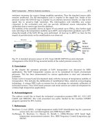
The PCD or PCBN in ultrahard tool blanks often is bonded to a cemented carbide substrate (Fig. 11), which allows
brazing to tool shanks or to indexable inserts for use in standard toolholders. Solid PCD and PCBN can also be used as
inserts.
Fig. 11
Polycrystalline diamond with substrates. (a) Typical fully round PCD tool blank. This type of blank is brazed or mechanically
clamped to extend the usable cutting ed
ge. (b) Typical square PCD tool blank with a long straight cutting edge that is ideal for many
applications. (c) Typical triangular PCD tool blank that is useful in single-point turning applications, either as tools or as brazed-
in tips on
carbide tools
The types of metals typically machined with ultrahard tool materials are summarized in Table 4. More detailed
information on tool fabrication and applications is available in the article "Ultrahard Tool Materials" in Machining,
Volume 16 of ASM Handbook, formerly 9th Edition Metals Handbook.
Polycrystalline diamond tool blanks are useful in the machining of nonferrous and nonmetallic materials (Tables 4 and 5)
and are commercially available in a variety of shapes and sizes (Fig. 12). An important variable for the end user is the
average grain size, which is separated into three grades in Fig. 13: fine (average diamond grain size, 4 μm), medium (5
μm), and coarse (25 μm). As shown in Fig. 13, differences in grain size can cause variations in abrasion resistance,
grindability, and workpiece surface finish. As a result of these differences, the areas of preferred application are different
for the three grades:
PCD grade Application
Fine grain Applications requiring good surface finishes; woodworking
Medium grain
General purpose applications (aluminum alloys with <16% Si)
Coarse grain Heavy-duty applications; milling applications, interrupted cuts (aluminum alloys with >16% Si)
Table 5 PCD tool applications
Application
Nonferrous materials
Silicon aluminum
Hypereutectic alloys
Hypoeutectic alloys
Copper alloys
Tungsten carbide
Nonmetallic materials
Woodworking
Fiberboard
Medium-density fiberboard
Chipboard
Hardboard
Composites
Graphite epoxy
Carbon-carbon fiber
Fiberglass plastic
Ceramics
Fig. 12
Various configurations and sizes of PCD tool blanks. Round shapes are available in standard sizes up to about 34 mm (1.34 in.) in
diameter.
Fig. 13
Variation in tool performance with average grain size in PCD tool blanks. (a) Abrasion resistance. (b) Grindability. (c) Surface finish.
Surface finish is also dependent on other factors such as feed rate, tool geometry, and workpiece condition.
The techniques for using PCD tool blanks are not very different from those for using conventional ceramic blanks. Where
possible, these guidelines should be followed:
• Use a positive rake
• Maintain a sharp cutting edge
• Use the largest nose radius possible
• Use a rigid machine set-up
• Minimize tool overhang
• Use a flood coolant whenever possible
When first machining a new material, the starting conditions suggested in Table 6 can be used. Slight modifications may
give improved results, depending on the particular configuration. Polycrystalline diamond tool blanks can be used dry; the
high thermal conductivity of the diamond layer removes and distributes heat generated at the cutting edge. However, tool
performance is generally improved by the use of coolants (Ref 15). Water-soluble oil emulsions, such as those used in
conventional machining with cemented tungsten carbide tools, are adequate if properly applied to the rake surface. They
reduce frictional heating and the formation of built-up edges while providing good chip flow.
Table 6 General starting conditions for PCD cutting tools
Speed Feed Workpiece material
m/min ft/min mm/rev in./rev
Aluminum alloys
4-8% Si 1280-1980
4200-6500
0.1-0.65 0.004-0.025
9-14% Si 1005-1585
3300-5200
0.1-0.5 0.004-0.020
16-18% Si 305-700 1000-2300
0.1-0.4 0.004-0.015
Copper alloys 610-1005 2000-3300
0.05-0.2 0.002-0.008
Plastics and composites 300-1005 1000-3300
0.1-0.3 0.004-0.012
Sintered tungsten carbide
20-40 65-130 0.15-0.25
0.006-0.010
Polycrystalline cubic boron nitride (PCBN) tool blanks are useful in the machining of iron, steel, and cobalt- and nickel-base
alloys (Tables 4 and 7). This makes them complementary to rather than competitive with the PCD tool blanks. They are
generally not recommended for use with superalloys or steels that have hardness of less than 35 and 45 HRC,
respectively. The causes and solutions of common problems encountered when using PCBN tools are listed in Table 8.
Table 7 PCBN tool applications
Application
Hard cast iron
Ni-Hard
Alloy cast iron
Chilled cast iron
Nodular cast iron
Soft cast iron
Gray cast iron
Sintered iron
Powder metallurgy products
Hardened steel
Tool steels
Die steels
Case-hardened steels
A, D, and M series steels
Bearing steels
Superalloys
Inconel 600, 718, and 901
René 77 and 95
Hastelloy
Waspaloy
Stellite
Table 8 Common problems encountered with PCBN tool blanks
Problem Cause Solution
Edge
chippage
Improper edge preparation Chamfer the cutting edge by 15° and 0.2 mm (0.008 in.); ensure a rigid
toolholding system
Cutting speed too slow (insufficient to soften
ahead of tool); or cutting speed too fast
(excessive heat generated)
Change speed to recommended rates: For hardened ferrous materials
(>45 HRC), 70-130 m/min (230-430 ft/min) For soft gray cast iron (200
HB), 450-915 m/min (1500-3000 ft/min)
Feed rate too light (thin chip cannot dissipate
heat; tool rubbing)
Use a minimum feed rate of 0.1 mm/rev (0.004 in./rev)
Rapid tool
flank wear
Depth of cut too light (excessive tool
rubbing)
Use a minimum depth of cut of 0.125 mm (0.005 in.)
Rapid tool
crater wear
Soft tool steel; cutting speed too high
(excessive heat)
Use only for steels with a minimum hardness of 45 HRC (see above for
speed recommendations)
Polycrystalline CBN blanks are available in a variety of shapes and sizes similar to those of polycrystalline diamond (Fig.
12). Polycrystalline CBN tool blanks can consist of a basic CBN layer (either solid or on a cemented carbide substrate) or
a composite abrasive layer (about half CBN and half ceramic). The composite blanks have excellent thermal and wear
resistance but lower impact resistance; therefore, they are less applicable to interrupted-cut machining. For milling
applications, basic PCBN blanks are preferred.
Tool Geometry. The general guidelines for the use of PCBN tools (Ref 15) are similar but not identical to those for PCD
tools. Negative-rake PCBN tools should be used wherever possible because they can withstand high cutting forces.
The lead or side cutting-edge angle should be as large as possible when using PCBN tools; it should only rarely be less
than 15°. A large lead angle spreads the cut over a wide section of the cutting edge, resulting in a thinner chip, which in
turn reduces loading on the tool blank or insert. The reduced loading allows the feed per revolution to be increased
without increasing the chances of cutting edge chippage. In addition, a large lead angle helps reduce notching at the
depth-of-cut line; notching can occur in an overly hard workpiece, or as the presence of scale on a workpiece.
Sharp corners on cutting tools concentrate stresses and can cause premature load failures. Honing a radius on the edge and
chamfering the cutting edge are two available methods for overcoming this problem. A chamfer of 15° with a width of 0.2
mm (0.008 in.) is recommended for most roughing operations. Honing the edge is slightly is suggested for finishing
operations (Ref 15).
Starting Feeds and Speeds. Good starting conditions are listed in Table 9 for several materials commonly machined with
PCBN tools. While feeds and speeds are dependent on workpiece properties, the conditions given in Table 9 generally
produce satisfactory result. In the speed ranges shown, the higher speeds are for finishing operations. It is recommended
that cutting fluids be used whenever possible.
Table 9 General starting conditions for PCBN cutting tools
Speed Feed Classification Material Type
m/min ft/min mm/rev
in./rev
Hardened ferrous materials
(>45 HRC)
Hardened steels (4340, 8620, M2, T15); hard cast irons
(chilled iron, Ni-Hard)
70-130 230-430 0.1-0.5 0.004-
0.020
Superalloys (>35 HRC) Nickel- and cobalt-base alloys (Inconel, René, Stellite,
Colmonoy)
200-
245
650-800 0.1-0.25
0.004-
0.010
Soft cast irons (typically 180-
240 HB)
Pearlitic gray iron, Ni-Resist 460-
915
1500-
3000
0.1-0.65
0.004-
0.025
Flame-sprayed materials Hardfacing materials 60-105 200-350 0.1-0.3 0.004-
0.012
Cold-sprayed materials Hardfacing materials 105-350-500 0.1-0.33
0.004-
Reference cited in this section
15.
S.F. Krar and E. Ratterman, Super-abrasives Grinding and Machining With CBN and Diamond, McGraw-
Hill, 1990
Structural Ceramics
Gerald L. DePoorter, Colorado Center for Advanced Ceramics, Department of Metallurgical and Materials Engineering, Colorado School of Mines; Terrence K. Brog
and Michael J. Readey, Coors Ceramics Company
Introduction
CERAMICS are nonmetallic, inorganic engineering materials processed at a high temperature. The general term
"structural ceramics" refers to a large family of ceramic materials used in an extensive range of applications. Included are
both monolithic ceramics and ceramic-ceramic composites. Chemically, structural ceramics include oxides, nitrides,
borides, and carbides. Many processing routes are possible for structural ceramics and are important because the
microstructure, and therefore the properties, are developed during processing.
General properties and uses of structural ceramics are reviewed first. Ceramic processing is described and the relationship
of processing, microstructure, and properties presented. Specific structural ceramic materials, including composites, are
presented. This article concludes with a discussion of future direction and problems with structural ceramics.
Uses and General Properties of Structural Ceramics
Industrial uses, required properties, and examples of specific applications for structural ceramics are summarized in Table
1. These applications take advantage of the temperature resistance, corrosion resistance, hardness, chemical inertness,
thermal and electrical insulating properties, wear resistance, and mechanical properties of the structural ceramic materials.
Combinations of properties for specific applications are summarized in Table 1. Ceramics offer advantages for structural