Harris'''' Shock and Vibration Handbook Part 14 docx
Bạn đang xem bản rút gọn của tài liệu. Xem và tải ngay bản đầy đủ của tài liệu tại đây (596.84 KB, 82 trang )
been occasionally used for shock isolation systems. However, in general, tension
loading is not recommended because of the resulting loads on the elastomer-to-
metal bond, which may cause premature failure of the material.
Buckling Loading. Buckling loading, illustrated in Fig. 32.2E, occurs when
the externally applied load causes an elastomeric element to warp or bend in the
direction of the applied load. Buckling stiffness characteristics may be used to
derive the benefits of both softening stiffness characteristics (for the initial part of
the load-deflection curve) and hardening characteristics (for the later part of the
load-deflection curve). The buckling mode thus provides high energy-storage
capacity and is useful for shock isolators where force or acceleration transmission
is important and where snubbing (i.e., motion limiting) is required under exces-
sively high transient dynamic loads.This type of stiffness characteristic is exhibited
by certain elastomeric cushioning foam materials and by specially designed elas-
tomeric isolators. However, it is important to note that even simple compressive
elements will buckle when the slenderness ratio (the unloaded length/width ratio)
exceeds 1.6.
Combinations of the types of loading described above are commonly used, which
result in combined load-deflection characteristics. Consider, for example, a com-
pression-type isolator which is installed at an angle instead of in the usual vertical
position. Under these conditions, it acts as a compression-shear type of isolator
when loaded in the vertical downward direction.When loaded in the vertical upward
direction, it acts as a shear-tension combination type of isolator.
Static and Dynamic Stiffness. When the main load-carrying spring is made of
rubber or a similar elastomeric material, the natural frequency calculated using the
stiffness determined from a static load-deflection test of the spring almost invariably
gives a value lower than that experienced during vibration. Thus the dynamic mod-
ulus appears greater than the static modulus. The ratio of moduli is approximately
independent of the velocity of strain, and has a numerical value generally between 1
and 3. This ratio increases significantly as the durometer increases.
Damping Characteristics. Damping, to some extent, is inherent in all resilient
materials. The damping characteristics of elastomers vary widely. A tightly cured
elastomer may (within its proper operating range) store and return energy with
more than 95 percent efficiency, while elastomers compounded for high damping
have less than 30 percent efficiency.Damping increases with decreasing temperature
because of the effects of crystallinity and viscosity in the elastomer. If the isolator
remains at a low temperature for a prolonged period, the increase in damping may
exceed 300 percent. Damping quickly decreases with low-temperature flexure,
because of the crystalline structure deterioration and the heat generated by the high
damping.
Where the nature of the excitation is difficult to predict (for example, random
vibration), it is desirable that the damping in the isolator be relatively high. Damp-
ing in an isolator is of the greatest significance at the resonance frequency. There-
fore, it is desirable that isolators embody substantial damping when they may
operate at resonance, as is the case when the excitation is random over a broad fre-
quency band or even momentary (as in the starting of a machine with an operating
frequency greater than the natural frequency of the machine on its isolators). The
relatively large amplitude commonly associated with resonance does not occur
instantaneously, but rather requires a finite time to build up. If the forcing frequency
is varied continuously as the machine starts or stops, the resonance condition may
exist for such a short period of time that only a moderate amplitude builds. The rate
SHOCK AND VIBRATION ISOLATORS AND ISOLATION SYSTEMS 32.7
8434_Harris_32_b.qxd 09/20/2001 12:32 PM Page 32.7
of change of forcing frequency is of little importance for highly damped isolators, but
it is of considerable importance for lightly damped isolators.
In general, damping in an elastomer increases as the frequency increases. The
data of Figs. 33.5 and 33.6 can be used to predict transmissibility at resonance by esti-
mating the frequency and the amplitude of dynamic shear strain; then the fraction of
critical damping is obtained from the curves and used with Eq. (30.1) to calculate
transmissibility at resonance.
Hydraulically Damped Vibration Isolators. Hydraulically damped vibration
isolators combine a spring and a damper in a single compact unit that allows tun-
ing of the spring and damper independently. This provides flexibility in matching
the dynamic characteristics of the isolator to the requirements of the application.
Hydraulic mounts have been used primarily as engine and operator cab isolators
in vehicular applications. The hydraulically damped isolator, described in Ref. 2,
has a flexible rubber element that encapsulates an incompressible fluid which
is made to flow through a variety of ports and orifices to develop the dynamic
characteristics required. The fluid cavity is divided into two chambers with an ori-
fice between, so that motion of the elastomeric element causes fluid to flow from
one chamber to the other, dissipating energy (and thus creating damping in the
system).
Installations that require a soft isolator for good isolation may also require
motion control under transient (shock) inputs or when operating close to the isola-
tion system’s resonant frequency. For good isolation, low damping is required. For
motion control, high damping is required. Fluid-damped isolators accommodate
these conflicting requirements. A hydraulically damped vibration isolator can also
act as a tuned absorber by increasing the length of the orifice into an inertia track
because the inertia of the fluid moving within the isolator acts as a tuned mass at a
specific frequency (which is determined by the length of the orifice).This feature can
be used where vibration isolation at a particular frequency is required.
PLASTIC ISOLATORS
Isolators fabricated of resilient plastics are available and have performance charac-
teristics similar to those of the rubber-to-metal type of isolators of equivalent con-
figuration.The structural elements are manufactured from a rigid thermoplastic and
the resilient element from a thermoplastic elastomer. These elements are compati-
ble in the sense that they are capable of being bonded one to another by fusion. The
most commonly used materials are polystyrene for the structural elements and buta-
diene styrene for the resilient elastomer.The advantages of this type of spring are (1)
low cost, (2) exceptional uniformity in dynamic performance and dimensional sta-
bility, and (3) ability to maintain close tolerances. The disadvantages are (1) limited
temperature range, usually from a maximum of about 180°F (82°C) to a minimum of
−40°F (−40°C), (2) creep of the elastomer element at high static strains, and (3) the
structural strength of the plastic.
METAL SPRINGS
Metal springs are commonly used where large static deflections are required, where
temperature or other environmental conditions make elastomers unsuitable, and (in
some circumstances) where a low-cost isolator is required. Pneumatic (air) springs
32.8 CHAPTER THIRTY-TWO
8434_Harris_32_b.qxd 09/20/2001 12:32 PM Page 32.8
provide unusual advantages where low-frequency isolation is required; they can be
used in many of the same applications as metal springs, but without certain disadvan-
tages of the latter. Metal springs used in shock and vibration control are usually cat-
egorized as being of the following types: helical springs (coil springs), ring springs,
Belleville (conical or conical-disc) springs, involute (volute) springs, leaf and can-
tilever springs, and wire-mesh springs.
Helical Springs (Coil Springs). Heli-
cal springs (also known as coil springs)
are made of bar stock or wire coiled into
a helical form, as illustrated in Fig. 32.3.
The load is applied along the axis of
the helix. In a compression spring the
helix is compressed; in a tension spring it
is extended. The helical spring has a
straight load-deflection curve, as shown
in Fig. 32.4.This is the simplest and most
widely used energy-storage spring. En-
ergy stored by the spring is represented
by the area under the load-deflection
curve.
Helical springs have the inherent
advantages of low cost, compactness,
and efficient use of material. Springs of
this type which have a low natural fre-
quency when fully loaded are available.
For example, such springs having a nat-
ural frequency as low as 2 Hz are rela-
tively common. However, the static
deflection of such a spring is about 2.4
in. (61 mm). For such a large static
deflection, the spring must have ade-
quate lateral stability or the mounted
equipment will tip to one side. There-
fore, all forces on the spring must be
along the axis of the spring. For a given
natural frequency, the degree of lateral
stability depends on the ratio of coil
diameter to working height. Lateral sta-
bility also may be achieved by the use of
a housing around the spring which re-
stricts its lateral motion. Helical springs
provide little damping, which results
in transmissibility at resonance of 100
or higher. They effectively transmit
high-frequency vibratory energy and
therefore are poor isolators for struc-
ture-borne noise paths unless they are
used in combination with an elastomer
which provides the required high-
frequency attenuation, as illustrated in
Fig. 32.5.
SHOCK AND VIBRATION ISOLATORS AND ISOLATION SYSTEMS 32.9
FIGURE 32.3 Cross section of a helical spring
showing the direction of the applied force F.
FIGURE 32.4 Load-deflection curve for a hel-
ical spring.
FIGURE 32.5 Helical spring isolator for
mounting machinery.
8434_Harris_32_b.qxd 09/20/2001 12:32 PM Page 32.9
Ring Springs. A ring spring, shown in
Fig. 32.6A, absorbs the energy of motion
in a few cycles, dissipating it as a result
of friction between its sections. With a
high load capacity for its size and weight,
a ring spring absorbs linear energy with
minimum recoil. It has a linear load-
deflection characteristic, shown in Fig.
32.6B. Springs of this type often are used
for loads of from 4000 to 200,000 lb
(1814 to 90,720 kg), with deflections
between 1 in. (25 mm) and 12 in. (305
mm).
Belleville Springs. Belleville springs
(also called coned-disc springs), illus-
trated in Fig. 32.7, absorb more energy in
a given space than helical springs. Springs
of this type are excellent for large loads
and small deflections. They are available
as assemblies, arranged in stacks. Their
inherent damping characteristics are like
those of leaf springs: Oscillations quickly
stop after impact. The coned discs of this
type of spring have diametral cross sec-
tions and loading, as shown in Fig. 32.7.
The shape of the load-deflection curve
depends primarily on the ratio of the
unloaded cone (or disc) height h to the
thickness t. Some load-deflection curves
are shown in Fig. 32.8 for different values
of h/t, where the spring is supported so
that it may deflect beyond the flattened
position. For a ratio of h/t approximately
equal to 0.5, the curve approximates a
straight line up to a deflection equal to
half the thickness; for h/t equal to 1.5,
the load is constant within a few percent
over a considerable range of deflection.
Springs with ratios h/t approximating 1.5
are known as constant-load or stiffness
springs. Advantages of Belleville springs
include the small space requirement in
the direction of the applied load, the abil-
ity to carry lateral loads, and load-
deflection characteristics that may be
changed by adding or removing discs.
Disadvantages include nonuniformity of
stress distribution, particularly for large
ratios of outside to inside diameter.
Involute Springs. An involute spring, shown in Fig. 32.9A and 32.9B, can be used
to better advantage than a helical spring when the energy to be absorbed is high and
32.10 CHAPTER THIRTY-TWO
FIGURE 32.6 Ring spring. (A) Cross section.
(B) Load-deflection characteristic when it is
loaded and when it is unloaded.
FIGURE 32.7 A Belleville spring made up of
a coned disc of thickness t and height h, axially
loaded by a force F.
FIGURE 32.8 The load-deflection character-
istic for a Belleville spring having various ratios
of h/t.
8434_Harris_32_b.qxd 09/20/2001 12:32 PM Page 32.10
space is rather limited. Isolators of this type have a nonlinear load-deflection charac-
teristic, illustrated in Fig. 32.9C. They are usually much more complex in design than
helical springs.
SHOCK AND VIBRATION ISOLATORS AND ISOLATION SYSTEMS 32.11
FIGURE 32.11 Wire-mesh spring, shown in section.
FIGURE 32.9 An involute spring. (A) Side view. (B) Cross sec-
tion. (C) Load-deflection characteristic.
Leaf Springs. Leaf springs are some-
what less efficient in terms of energy
storage capacity per pound of metal
than helical springs. However, leaf
springs may be applied to function as
structural members. A typical semiellip-
tic leaf spring is shown in Fig. 32.10.
Wire-Mesh Springs. Knitted wire
mesh acts as a cushion with high damp-
ing characteristics and nonlinear spring constants.A circular knitting process is used
to produce a mesh of multiple, interlocking springlike loops. A wire-mesh spring,
shown in Fig. 32.11, has a multidirectional orientation of the spring loops, i.e., each
FIGURE 32.10 Semielliptic leaf spring.
8434_Harris_32_b.qxd 09/20/2001 12:32 PM Page 32.11
loop can move freely in three directions, providing a two-way stretch. Under tensile
or compressive loads, each loop behaves like a small spring; when stress is removed,
it immediately returns to its original shape. Shock loadings are limited only by the
yield strength of the mesh material used. The mesh cushions, enclosed in springs,
have characteristics similar to a spring and dashpot.
Commonly used wire mesh materials include such metals as stainless steel, galva-
nized steel, Monel, Inconel, copper, aluminum, and nickel. Wire meshes of stainless
steel can be used outside the range to which elastomers are restricted, i.e., −65 to
350°F (−53 to 177°C); furthermore, stainless steel is not affected by various environ-
mental conditions that are destructive to elastomers. Wire-mesh springs can be fab-
ricated in numerous configurations, with a broad range of natural frequency,
damping, and radial-to-axial stiffness properties. Wire-mesh isolators have a wide
load tolerance coupled with overload capacity. The nonlinear load-deflection char-
acteristics provide good performance, without excessive deflection, over a wide load
range for loads as high as four times the static load rating.
Stiffness is nonlinear and increases with load, resulting in increased stability and
gradual absorption of overloads. An isolation system has a natural frequency pro-
portional to the ratio of stiffness to mass; therefore, if the stiffness increases in pro-
portion to the increase in mass, the natural frequency remains constant. This
condition is approached by the load-deflection characteristics of mesh springs. The
advantages of such a nonlinear system are increased stability, resistance to bottom-
ing out of the mounting system under transient overload conditions, increased shock
protection, greater absorption of energy during the work cycle, and negligible drift
rate. Critical damping of 15 to 20 percent at resonance is generally considered desir-
able for a wire-mesh spring. Environmental factors such as temperature, pressure,
and humidity affect this value little, if at all. Damping varies with deflection: high
damping at resonance and low damping at higher frequencies.
AIR (PNEUMATIC) SPRINGS
A pneumatic spring employs gas as its resilient element. Since the gas is usually air,
such a spring is often called an air spring. It does not require a large static deflec-
tion; this is because the gas can be compressed to the pressure required to carry the
load while maintaining the low stiffness necessary for vibration isolation. The
energy-storage capacity of air is far greater per unit weight than that of mechanical
spring materials, such as steel and rubber. The advantage of air is somewhat less
than would be indicated by a comparison of energy-storage capacity per pound of
material because the air must be contained. However, if the load and static deflec-
tion are large, the use of air springs usually results in a large weight reduction.
Because of the efficient potential energy storage of springs of this type, their use in
a vibration-isolation system can result in a natural frequency for the system which
is almost 10 times lower than that for a system employing vibration isolators made
from steel and rubber.
An air spring consists of a sealed pressure vessel, with provision for filling and
releasing a gas, and a flexible member to allow for motion. The spring is pressurized
with a gas which supports the load. Air springs generally have lower resonance fre-
quencies and smaller overall length than mechanical springs having equivalent char-
acteristics; therefore, they are employed where low-frequency vibration isolation is
required. Air springs may require more maintenance than mechanical springs and
are subject to damage by sharp and hot objects. The temperature limits are also
restricted compared to those for mechanical springs.
32.12 CHAPTER THIRTY-TWO
8434_Harris_32_b.qxd 09/20/2001 12:32 PM Page 32.12
Figure 32.12 shows four of the most common types of air springs. The air spring
shown in Fig. 32.12A is available with one, two, and three convolutions. It has a
very low minimum height and a stroke that is greater than its minimum height.The
rolling lobe (reversible sleeve) spring shown in Fig. 32.12B has a large stroke capa-
bility and is used in applications which require large axial displacements, as, for
example, in vehicle applications. The isolators shown in Fig. 32.12A and B may
have insufficient lateral stiffness for use without additional lateral restraint. The
rolling diaphragm spring shown in Fig. 32.12C has a small stroke and is employed
to isolate low-amplitude vibration. The air spring shown in Fig. 32.12D has a low
height and a small stroke capability. The thick elastomer sidewall can be used to
cushion shock inputs.
The load F that can be supported by an air spring is the product of the gage pres-
sure P and the effective area S (i.e., F = PS). For a given area, the pressure may be
adjusted to carry any load within the strength limitation of the cylinder walls. Since
the cross section of many types of air springs may vary, it is not always easy to
determine. For example, the spring shown in Fig. 32.12A has a maximum effective
area at the minimum height of the spring and a smaller effective area at the maxi-
mum height.The spring illustrated in Fig. 32.12B is acted on by a piston which is con-
toured to vary the effective area. In vehicle applications this is often done to provide
a low spring stiffness near the center of the stroke and a higher stiffness at both ends
of the stroke in order to limit the travel.The effective areas of the springs illustrated
in Fig. 32.12C and D are usually constant throughout their stroke; the elastomeric
diaphragm of the spring shown in Fig. 32.12D adds significantly to its stiffness. Air
springs are commercially available in various sizes that can accommodate static
loads that range from as low as 25 lb (11.3 kg) to as high as 100,000 lb (45,339 kg)
with a usable temperature range of from −40 to 180°F (−40 to 83°C). System natural
frequencies as low as 1 Hz can be achieved with air springs.
SHOCK AND VIBRATION ISOLATORS AND ISOLATION SYSTEMS 32.13
FIGURE 32.12 Four common types of air springs. (A) Air spring with convolutions. (B) A
rolling lobe air spring. (C) Rolling diaphragm air spring. (D) Air spring having a diaphragm
and an elastomeric sidewall.
8434_Harris_32_b.qxd 09/20/2001 12:32 PM Page 32.13
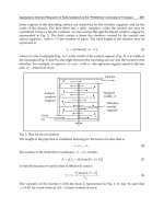
Stiffness. The stiffness of the air
spring of Fig. 32.13 is derived from the
gas laws governing the pressure and vol-
ume relationship. Assuming adiabatic
compression, the equation defining the
pressure-volume relationship is
PV
n
= P
i
V
i
n
(32.1)
where P
i
= absolute gas pressure at
reference displacement
V
i
= corresponding volume of
contained gas
n = ratio of specific heats of
gas, 1.4 for air
If the area S is constant, and if the change in volume is small relative to the initial
volume V
i
[i.e., if Sδ (where δ is the dynamic deflection) << V
i
)], then the stiffness k
is given by
k = (32.2)
Transverse Stiffness. The transverse stiffness (i.e., the stiffness to laterally
applied forces) of the air springs illustrated in Fig. 32.12A and B varies from very
small to moderate; the natural frequencies for such springs vary from 0 to 3 Hz. The
spring illustrated in Fig. 32.12C has a higher transverse stiffness, with natural fre-
quencies ranging from 2 to 8 Hz. The spring illustrated in Fig. 32.12D has a moder-
ate transverse stiffness; the natural frequency varies in the range from 3 to 5 Hz. If
an installation requires the selection of an air spring having insufficient transverse
stiffness, additional springs in the transverse direction are often employed for stabil-
ity, as shown in Fig. 32.14.
At frequencies above 3 Hz, the compression of gases used in air springs tends to
be adiabatic and the ratio of specific heats n for both air and nitrogen has a value of
1.4.At frequencies below approximately
3 Hz, the compression tends to be
isothermal and the ratio of specific heats
n has a value of 1.0, unless the spring is
thermally insulated. For thermally insu-
lated springs, the transition from adia-
batic to isothermal occurs at a frequency
of less than 3 Hz. Gases other than air
which are compatible with the air spring
materials can also be used. For example,
sulfur hexafluoride (SF
6
) has a value of
n equal to 1.09—a value that reduces the
axial spring stiffness by 22 percent; it
also has a considerably lower perme-
ation (leakage through the air spring
material) rate than air, which may reduce the frequency of recharging (repressuriz-
ing) for a closed (passive) air spring.
Damping. Air springs have some inherent damping that is developed by damping
in the flexible diaphragm or sidewall, friction, damping of the gas, and nonlinearity.
nP
i
S
2
ᎏ
V
i
32.14 CHAPTER THIRTY-TWO
FIGURE 32.13 Illustration of a single-acting
air spring consisting of a piston and a cylinder.
FIGURE 32.14 An air spring used to support a
load and provide vibration isolation in the verti-
cal direction. In addition, air springs are pro-
vided on the sides to increase the transverse
stiffness.
8434_Harris_32_b.qxd 09/20/2001 12:32 PM Page 32.14
The damping varies with the vibration amplitude; however, it generally is between 1
and 5 percent of critical damping.
Natural Frequency. In U.S. Customary units, the natural frequency f
n
of an
undamped air spring is expressed by
f
n
= 3.13
1/2
=δ
1
−1/2
(32.3a)
where W = supported weight, lb
k
1
= stiffness of the air spring, lb/in.
δ
1
= static deflection, in.
In S.I. units, the natural frequency is given by
f
n
=δ
2
−1/2
(32.3b)
where δ
2
= static deflection, cm
ISOLATORS IN COMBINATION
When a number of isolators are used in a system, they are usually combined either
in parallel or in series or in some combination thereof.
ISOLATORS IN PARALLEL
Most commonly, isolators are arranged in parallel. Figure 32.15 depicts three isola-
tors schematically as springs in parallel. A number of vibration isolators are said to
be in parallel if the static load supported is divided among them so that each isola-
tor supports a portion of the load. If the stiffness of each of the n isolators in Fig.
32.15 is represented by k, the stiffness of the combination is given by
Stiffness of n isolators in parallel = nk (32.4)
k
1
ᎏ
W
SHOCK AND VIBRATION ISOLATORS AND ISOLATION SYSTEMS 32.15
FIGURE 32.15 Schematic diagram of three
springs in parallel. Individual spring loads are added
to obtain the total weight. With the static load equal
on all springs, the static deflection of each spring is
the same.
8434_Harris_32_b.qxd 09/20/2001 12:32 PM Page 32.15
Since in Fig. 32.15 isolator spacing is symmetrical in relation to the center-of-gravity
and the same isolator is used at all support points, the stiffness of the combination is
3 times the stiffness of a single isolator, and the static deflection is the same at each
isolator.
ISOLATORS IN SERIES
When three isolators are combined in
series, as shown in Fig. 32.16, the static
load is transmitted from one isolator to
the next. If the static weight is supported
by n isolators in series, each having the
stiffness k, the stiffness of the combina-
tion is given by
Stiffness of n isolators in series
=
(32.5)
Thus, if the mass is supported by three
identical isolators (Fig. 32.16), the stiff-
ness of this combination is one-third the
stiffness of a single isolator, and the static
deflection is the sum of the deflection of
the individual isolators (or 3 times the
static deflection of a single isolator).
ISOLATOR SELECTION
IMPORTANT FACTORS AFFECTING SELECTION
Stiffness and damping are the basic properties of an isolator which determine its use
in a system designed to provide vibration isolation and/or shock isolation. These
properties usually are found in isolator supplier literature. However, the following
other important factors must be considered in the selection of an isolator:
Type and Direction of Disturbance. The source of a dynamic disturbance (shock
or vibration) influences the selection of an isolator in several ways. For example, a
decision can be made whether to isolate the source of the disturbance or to isolate
the item being disturbed. This decision affects which isolator is to be used. Consider
the operation of a heavy punch press which has an adverse effect on a nearby elec-
tronic instrument. Isolation of the punch press would reduce this effect but would
require fairly large isolators which might have to be resistant to grease or oil. In con-
trast, isolation of the instrument would also provide the required protection, but the
required isolators would be smaller and (since grease or oil would not be a consid-
eration) could be fabricated of a preferred elastomer.
A knowledge of the source of the vibration can aid in defining the problem to be
solved.Within a given industry there may be published material describing problems
similar to the one under consideration. Such material may describe possible solu-
tions plus equipment fragility, and/or dynamic characteristics of the equipment.
k
ᎏ
n
32.16 CHAPTER THIRTY-TWO
FIGURE 32.16 Schematic diagram of three
springs in series. Individual spring deflections
are added to obtain total deflection, but each
spring carries the total load.
8434_Harris_32_b.qxd 09/20/2001 12:32 PM Page 32.16
Type of Disturbance. The dynamic environment can be delineated into three
categories: (1) periodic vibration—sinusoidal continuos motion or acceleration
occurring at discrete frequencies, (2) random vibration—the simultaneous existence
of any and all frequencies and amplitudes in any and all phase relationships as exem-
plified by noise, and (3) transient phenomenon (shock)—a nonperiodic sudden
change of velocity,acceleration, or displacement.Usually some combination of these
three categories occurs in most isolation systems. A knowledge of the dynamic dis-
turbance is very important in the choice of an isolator. For example, in the case of an
instrument supported by isolators, the resilient mounts permit the supported body
to “stand still” by virtue of its own inertia while the support structure generates peri-
odic or random vibration. In contrast, shock attenuation involves the storage by the
isolators of the dynamic energy which impacts on the support structure and the sub-
sequent release of the energy over a longer period of time at the natural frequency
of the system. If only a vibration disturbance is present, a small isolator normally is
suitable since vibration amplitudes usually are small relative to shock amplitudes. If
a shock disturbance is the primary problem, then a larger isolator with more inter-
nal space for motion is required.
In selecting an isolator, ensure (1) that there is enough deflection capability in
the isolator to accommodate the maximum expected motions from the dynamic
environment, (2) that the load-carrying capacity of the isolator will not be exceeded;
the maximum loads due to vibration and/or shock should be calculated and checked
against the rated maximum dynamic load capacity of the isolator, and (3) that there
will be no problem as a result of overheating of the isolator or fatigue deterioration
due to long-term high-amplitude loading.
Direction of Disturbance. A factor that must be considered in the selection of
an isolator is that of the directions (axes) of the disturbance. If the vibration or shock
input occurs only in one direction, usually a simple isolator can be selected; its char-
acteristics need be specified along only one axis. In contrast, if the vibration or shock
is expected to occur along more than one axis, then the selected isolator must pro-
vide isolation (and its characteristics must be specified) along all the critical axes.
For example, consider an industrial machine which produces troublesome vibration
in the vertical direction and which must be isolated from its supporting structure. In
this case, a standard plate-type isolator may be used.This type isolator is stiffer in the
horizontal direction than in the vertical direction, which is the axis of the primary
disturbance; the horizontal stiffness does not significantly affect the motion of the
isolator in the vertical direction. Such horizontal stiffness adds to the lateral stability
of the installation.
Allowable Response of a System to the Disturbance. The allowable response
of a system is defined as the maximum allowable transmitted shock or vibration and
the maximum displacements due to such disturbances. The allowable response of a
system can be expressed in any of the following ways:
●
Maximum acceleration loading due to a shock input
●
Specific system natural frequency and maximum transmissibility at that frequency
●
Maximum acceleration, velocity, or displacement allowable over a broad fre-
quency range
●
The allowable level of vibration at some critical frequency or frequencies
●
Maximum displacement due to shock loading
The maximum acceleration which a piece of equipment can withstand without
damage or malfunction is often called fragility. The definition of some allowable
SHOCK AND VIBRATION ISOLATORS AND ISOLATION SYSTEMS 32.17
8434_Harris_32_b.qxd 09/20/2001 12:32 PM Page 32.17
response is necessary for an appropriate isolator selection. If fragility data are not
available for the specific equipment or installation at hand, then examples of similar
situations should be used as a starting point. Suppose an isolator were chosen only
for its load-carrying capability, with no regard for the fragility of a piece of equip-
ment in a specific frequency range. Then, the natural frequency of the system might
be incorrectly placed such that a resonance within the equipment might be excited
by the isolation system.
Space and Locations Available for Isolators. Vibration and shock isolation
should be considered as early as possible in the design of a system, and an estimate
of isolator size should be made based on isolator literature. The size of the isolator
depends on the nature and magnitude of the expected dynamic disturbances and the
load to be carried. Typical literature describes the capabilities of isolators based on
such factors.
The location of isolators is very important to the dynamics of the equipment
mounted on them. For example, a center-of-gravity installation, as shown in Fig.
32.17, allows the mounted equipment to move only in straight translational modes
(i.e., a force at the center-of-gravity does not cause rotation of the equipment). This
32.18 CHAPTER THIRTY-TWO
Equidistant
Elevation
(a)
Plan
(
c
)
Elevation
(
d
)
Elevation
(b)
CG
CG
AA
Equidistant
A A
Equidistant
B
B
CG CG
FIGURE 32.17 Center-of-gravity installations of vibration isolators: (A)
Center-of-gravity horizontal support. (B) Center-of-gravity diagonal support.
(C) Symmetrical spacing about the center-of-gravity. (D) Center-of-gravity ver-
tical support. (After Davey and Payne.
2
)
8434_Harris_32_b.qxd 09/20/2001 12:32 PM Page 32.18
minimizes the motion of the corners of the equipment and allows the most efficient
installation from the standpoint of space requirements and isolation efficiency.
If the isolators cannot be located so as to provide a center-of-gravity installa-
tion, then the system analysis is more difficult and more space must be allowed
around the equipment to accommodate rocking motion (i.e., rotational modes) of
the system. Finally, the isolators must be double-checked to ensure that they
are capable of withstanding the additional loads and motions from the non-
translational movement of the equipment. This is particularly true when the
center-of-gravity is a significant distance above or below the plane in which the
isolators are located. Rule of thumb:The distance between the isolator plane and
the center-of-gravity should be equal to or less than one-third of the minimum
spacing between isolators. This helps to minimize rocking of the equipment and
the resultant high stress in the isolators.
Weight and Center-of-Gravity of Supported Equipment. The weight and loca-
tion of the center-of-gravity of the supported equipment should be determined. The
location of the center-of-gravity is necessary for calculating the load supported on
each mount. It is best to keep the equipment at least satatically balanced [essentially
equal deflections on all isolators (see Fig. 32.17)]. The preferred approach is to use
the same isolator at all points, choosing isolator locations such that static loads (and
thus deflections) are equalized. If this is not practical, isolators of different load rat-
ings may be required at different support points on the equipment for optimum iso-
lation.The size of the equipment and the mass distribution are important in dynamic
analyses of the isolated system.
Space Available for Equipment Motion. The choice of an isolator may depend
on the space available (commonly called sway space) around a piece of equipment.
The spring constant of the isolator should be chosen carefully so that motion is kept
within defined space limits. The motion which must be considered is the sum of (1)
the static deflection due to the weight supported by the isolator, (2) the deflection
caused by the dynamic environment, and (3) the deflection due to any steady-state
acceleration (such as in a maneuvering aircraft).
If there is a problem of excessive motion of the supported mass on the isolator,
then a snubber (i.e., a device which limits the motion) can be used.A snubber may be
an elastomeric compression element designed into an isolator. Captive-type isola-
tors (see Fail-Safe Installation) have built-in motion-limiting stops. Also, elastomers
stressed in compression have natural snubbing due to the nonlinear load-deflection
characteristics. In some cases it may be necessary to limit motion by separately
installed snubbers such as a compression pad at the point of excessive motion as
shown in Fig. 32.18.The spring constant of such a snubber must be carefully selected
to avoid transmission of high-impact loads into the supported equipment.
Ambient Environment. The environment in which an isolator is to be used
affects its selection in two ways:
1. Some environmental conditions may degrade the physical integrity of the isola-
tor and make it nonfunctional.
2. Some environmental conditions may change the operating characteristics of an
isolator, without causing permanent damage.
This may alter the characteristics of the isolation system of the supported equip-
ment; for example, frequency responses could change significantly with changes in
SHOCK AND VIBRATION ISOLATORS AND ISOLATION SYSTEMS 32.19
8434_Harris_32_b.qxd 09/20/2001 12:32 PM Page 32.19
the ambient temperature. Thus, it is important to determine the operating environ-
ment of the isolation system and to select isolators that will function with desired
characteristics in this environment.
Available Isolator Materials. Vibration and shock isolators are available in a
wide variety of materials and configurations to fit many different situations.The type
of isolator is chosen for the load and dynamic conditions under which it must oper-
ate. The material from which the isolator is made depends to a great extent on the
ambient environment of an application and somewhat on the dynamic properties
required. Guidance for the choice of isolator materials is given earlier in this chap-
ter. Chapter 33 describes the engineering properties of rubber.
Metal-spring isolators are used primarily where operating temperatures are too
high for elastomeric isolators. They can be used in a variety of applications.
By far, the majority of isolators in use today are elastomeric. The development
of a vast array of elastomeric compounds has made it possible to use this type of
isolator in almost any environment. Within a given type of elastomer, it is a simple
matter to vary the stiffness (modulus, durometer) of the compound; this gives much
flexibility in adapting an isolator to an application without changing the isolator’s
geometry.
Since the selection of material for an isolator depends so much on the environ-
ment in which the mount will be used, it is very important to learn as much as possi-
ble about the operating and storage environments.
Desired Service Life. The expected, or desired, length of service for an isolator
can affect the type and size of the vibration isolator which is selected. For example,
an isolator which must operate for 2000 hours under a given set of conditions typi-
cally is larger than one which must operate for only 500 hours under the same con-
ditions.
32.20 CHAPTER THIRTY-TWO
FIGURE 32.18 A vibration isolator provided with auxiliary elas-
tomeric snubbers to limit the motion of the isolator in the horizontal
and vertical directions; these snubbers provide a “cushion” stop to pro-
vide a lower shock force on the equipment than would be experienced
with a metal-to-metal stop.
8434_Harris_32_b.qxd 09/20/2001 12:32 PM Page 32.20
In general, empirical data are used to estimate the operating life of an isolator.
Accurate descriptions of the dynamic disturbances and ambient operating environ-
ment expected are needed to make an estimate of isolator life. A knowledge of the
specific material and design factors in an isolator is necessary to make an estimate of
fatigue life. Such information is best provided by the original manufacturer or
designer of the isolator.
Requirement for Fail-Safe Operation. Many pieces of equipment must be
mounted on isolators on which the equipment remains supported (in place) in the
event of mechanical failure of the isolator, i.e., until it can be replaced. This feature
may be provided by a metal-to-metal interlock, or it may be provided by snubbers,
as illustrated in Fig. 32.18. A snubber is a component in a resilient isolator which lim-
its the displacement of the isolator in the event of its failure.
Interaction with Support Structure. The support structure characteristics
can also affect the selection of isolators. An isolator must deflect if it is to isolate
vibration; generally the greater the deflection, the greater the isolation. The isolator
functions by being soft enough to allow relative vibration amplitudes without trans-
mitting excessive force to the support structure. It is often assumed, in the selection
of vibration isolators, that the support structure is a rigid mass with infinite stiffness.
This assumption is not true since if the foundation were infinitely stiff, it would not
respond to a dynamic force and the isolator would not be needed. Since the founda-
tion does respond to dynamic forces, its response must affect the components that
are flexibly attached to it. In reality the support structure is a spring in series with the
isolator (see Isolators in Combination above) and springs in series carry the same
force and deflect proportionally to their respective spring constants.Thus if the stiff-
ness of the isolator is high compared to the stiffness of the foundation, the founda-
tion will deflect more than the isolator and actually nullify or limit the isolation
provided from the isolator itself. To achieve maximum efficiency from the selected
isolator, the spring constant of the support structure should be at least 10 times that
of the spring constant of the isolator attached to it. This will assure that at least 90
percent of the total system spring constant is contributed by the isolators and only
10 percent by the support structure.
Because the structure supporting a piece of equipment has inherent flexibility, it
has resonances which could cause amplification of vibration levels; these resonance
frequencies must be avoided in relation to isolated system natural frequencies.
HOW TO SELECT ISOLATORS
The isolator selection process should proceed in the following steps:
Step 1. Required isolation efficiency. First, indicate the percentage of isolation
efficiency that is desired. In general, an efficiency of 70 to 90 percent is desirable and
is usually possible to attain.
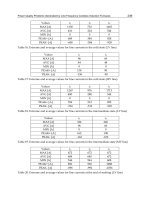
Step 2. Transmissibility. From Table 32.1 determine the maximum transmissi-
bility T of the system at which the required vibration isolation efficiency of Step 1
will be provided.
Step 3. Forcing frequency. Determine the value of the lowest forcing frequency
f (i.e., the frequency of vibration excitation). For example, in the case of a motor, the
SHOCK AND VIBRATION ISOLATORS AND ISOLATION SYSTEMS 32.21
8434_Harris_32_b.qxd 09/20/2001 12:32 PM Page 32.21
forcing frequency depends on the rotational speed, given in revolutions per minute
(rpm); the rotational speed must be divided by 60 sec/minute to obtain the forcing
frequency in cycles per second (Hz). The lowest forcing frequency is used because
this is the worst condition, resulting in the lowest value of f/f
n
(see Table 32.1). If a
satisfactory value of isolation efficiency is attained at this frequency, the vibration
reduction at higher frequencies will be even greater.
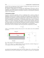
Step 4. Natural frequency. From Fig. 32.19, find the natural frequency f
n
of the
isolated system (i.e., the mass of the equipment supported on isolators) required to
provide a transmissibility T, determined in Step 2 (which is equivalent to a corre-
sponding percent vibration isolation efficiency) for a forcing frequency of f Hz
(determined in Step 3).
Step 5. Static deflection. From Fig. 32.19, determine the static deflection
required to provide a natural frequency of Step 4.
Step 6. Stiffness of isolation system. From Eq. (32.6), calculate the stiffness k
required to provide a natural frequency f
n
determined in Step 4:
f
n
= (32.6)
where W = the weight in pounds of the supported mass
g = the acceleration due to gravity in inches per second per second
Step 7. Stiffness of the individual vibration isolators. Determine the stiffness of
each of the n isolators from Eq. (32.4) or Eq. (32.5) depending on whether the vibra-
tion isolators are in parallel or in series. In general, they are in parallel so that the
required stiffness of each vibration isolator is 1/n times the value obtained in Step
6—assuming that all isolators share the load equally.
Step 8. Load on individual vibration isolators. Now calculate the load on each
individual isolator.
Step 9. Isolator selection. From a manufacturer’s catalog, elect a vibration iso-
lator which meets the stiffness requirement determined in Step 7 and which has a
load-carrying capacity (i.e., load rating) equal to the value obtained in Step 8. The
preferred approach is to use the same type and size isolator at all points of support;
[kg/W]
1/2
ᎏᎏ
2π
32.22 CHAPTER THIRTY-TWO
TABLE 32.1 Ratio of ( f/f
n
) Required to Achieve
Various Values of Vibration Isolation Efficiency
Isolation Maximum
efficiency, % transmissibility Required f/f
n
90 0.1 3.32
80 0.2 2.45
70 0.3 2.08
60 0.4 1.87
50 0.5 1.73
40 0.6 1.63
30 0.7 1.56
20 0.8 1.50
10 0.9 1.45
0 1.0 1.41
8434_Harris_32_b.qxd 09/20/2001 12:32 PM Page 32.22
choose isolator locations such that static loads (and thus deflections) are equalized.
If this is not practical, isolators of different load ratings may be required at different
support points on the equipment. If the vibration occurs only in one direction, usu-
ally a simple isolator can be selected; its characteristics need be specified along only
one axis. In contrast, if the vibration is expected to occur along more than one direc-
tion, then the selected isolator must provide isolation along all the critical axes.
EXAMPLES
The following examples present specific applications. They show how isolators may
be selected for some simple shock and vibration problems, but the steps used are
basic and can be extended to many other situations. In the solution of these prob-
lems, the following simplifying assumptions are made:
SHOCK AND VIBRATION ISOLATORS AND ISOLATION SYSTEMS 32.23
3.1
50
41.7
33.2
25
16.7
15
13.3
11.7
10
8.3
6.7
5.0
4.2
3.3
2.5
1.7
1.6 .88
Natural frequency, f
n
, Hz
Static deflection δ
st
, inches
.39 .22 .14 .01 .055 .035 .0165.5
0.50
Forcing frequency, f, Hz
0.67
0.83
1.0
1.17
1.33
1.5
1.67
2.50
3.33
5.00
6.67
8.33
10.0
13.3
16.7
25
Amplification
Percent isolation
Resonance
99.9 9999.5 98 97 96 95 90 80 70 60
FIGURE 32.19 Isolation efficiency chart.The vibration efficiency, in percent, is given as a function
of natural frequency of the isolated system (along the horizontal axis) and the forcing frequency, i.e.,
the frequency of excitation (along the vertical axis). The use of this chart is restricted to applications
where the vibration isolators are supported by a floor structure having a vertical stiffness of at least
15 times the total stiffness of the isolation system. This may require that the isolated structure be
placed along the length of a floor beam or that an additional floor beam be added to the structure.
8434_Harris_32_b.qxd 09/20/2001 12:32 PM Page 32.23
1. The effect of damping is negligible, a valid assumption for many isolator applica-
tions.
2. All modes of vibration are uncoupled, i.e., the isolators are symmetrically located
with respect to the mass center-of-gravity.
3. The static and dynamic spring constants of the isolators are equal, valid for low
modulus elastomers with little damping.
Example 32.1: Vibration Isolation. When a shock or vibration disturbance orig-
inates in the supported equipment, isolators which support the equipment reduce
the transmission of force to the supporting structure, thus protecting the structure or
foundation, for example, in isolating a vehicle chassis from the vibration of an inter-
nal combustion engine or in reducing the transmission of machine vibration to adja-
cent structures.
Problem. An electric motor and pump assembly, rigidly mounted on a com-
mon base, rotates at a speed of 1800 rpm and transmits vibration to other compo-
nents of a hydraulic system. The weight of the assembly and base is 140 lb (63 kg).
Four isolators are to be located at the corners of the rectangular base. The center-
of-gravity is centrally located in the horizontal plane near the base. The lowest
vibratory forcing frequency is 1800 rpm and is a result of rotational unbalance.
There also are higher frequencies due to magnetic and pump forces. The excitation
is in both the horizontal and vertical directions.
Objective. To reduce the amount of vibration transmitted to the supporting
structure and thus to other system components.A vibration isolation efficiency of 70
to 90 percent is usually possible to attain.
Solution:
1. Select a vibration isolation efficiency midway between 70 and 90 percent, i.e.,
80 percent.
2. Find the transmissibility T which corresponds to an isolation efficiency of 80
percent. From Eq. (32.7) or Fig 32.19, this is a value of T = 0.2.
Isolation efficiency = 100(1 − T) in percent (32.7)
where T = transmissibility.
3. Determine the lowest forcing frequency f by dividing the rotational speed in
rpm by 60, yielding a value of 30 Hz.
4. Next calculate the natural frequency f
n
required to provide the transmissibil-
ity T = 0.2 for a forcing frequency f = 30 Hz.According to Eq. (32.8), this is a value
of 12.2 Hz.
T = (32.8)
where f = the forcing frequency (also called disturbing frequency) in Hz
f
n
= system natural frequency in Hz
5. Then calculate the static deflection required to provide a natural frequency of
12.2 Hz. According to Eq. (32.9), this is a value of δ
st
= 0.066 in. (1.67 mm).
1
ᎏᎏ
( f/f
n
)
2
− 1
32.24 CHAPTER THIRTY-TWO
8434_Harris_32_b.qxd 09/20/2001 12:32 PM Page 32.24
f
n
= (32.9)
where δ
st
= the static deflection in inches
δ
st
= 0.066 in. (1.67 mm)
[The same results may be obtained by using the isolation efficiency chart, Fig.
32.19, as follows. Find the point at which the horizontal line for a forcing frequency
f = 30 Hz intersects the diagonal line for an isolation efficiency of 80 percent. From
the point of intersection, project a vertical line to read the values of δ
st
= 0.066 in.
(1.67 mm).]
6. Determine the stiffness of the required isolation system (i.e., combination of
four isolators) required to provide a natural frequency of f
n
. According to Eq.
(32.6), the value of stiffness of the system, for a weight of 140 lb, is 2120 lb/in. (371
N/mm).
7. Calculate the stiffness of individual isolators if one is placed in each corner by
dividing the value for the combination of isolators by 4, since all four support the
load.
8. The load on the individual isolator is equal to the total weight of the load
divided by the number of supporting isolators, i.e., 140/4 = 35 lb (15.8 kg) per iso-
lator.
Example 32.2: Shock Isolation. Mechanical shock may be transmitted through a
supporting structure to equipment, causing it to move. The transmitted motion and
force are reduced by mounting the equipment on isolators, for example, to protect
equipment from impacts during shipment.
Problem. A business machine is to be isolated so that it will not experience
damage during normal shipping. The unit can withstand 25g of shock without dam-
age. The suspended weight of 125 lb (56.2 kg) is to be equally distributed on four iso-
lators. The disturbances expected are those from normal transportation handling,
with no damage allowed after a 30-in. (762-mm) flat bottom drop. The peak vibra-
tion disturbances are normally in the range of 2 to 7 Hz.
Objective. To limit acceleration on the machine to 25g using the drop test as a
simulation of the worst expected shock conditions. A natural frequency between 7
and 10 Hz is desired to avoid the peak vibration frequency range and still provide
good shock protection.
Solution:
1. First, solve for the dynamic deflection δ
d
(displacement) of the machine
required to limit acceleration to X
F
(expressed in g’s) when the item is dropped from
a height (h = 30 in.) using:
δ
d
= (32.10)
Here
¨x
F
= the fragility factor = 25g, so that δ
d
= 2.4 in. (61 mm).
2h
ᎏ
¨x
F
3.13
ᎏ
(δ
st
)
1/2
SHOCK AND VIBRATION ISOLATORS AND ISOLATION SYSTEMS 32.25
8434_Harris_32_b.qxd 09/20/2001 12:32 PM Page 32.25
2. Then determine the required dynamic natural frequency f
n
to result in a
dynamic deflection δ
d
from Eq. (32.11), using a fragility
¨x
F
= 25g, h = 30 in., W = 125 lb
(56.2 kg), and δ
d
= 2.4 in.:
f
n
=
Ί
(32.11)
f
n
= 10 Hz (a value also given by use of Fig. 32.19).
3. Calculate the system dynamic spring constant k required to provide a dynamic
deflection δ
d
from:
k == (32.12)
k = 1302 lb/in. (228 N/mm) for the system.
4. From Eq. (32.4), calculate the system static spring constant of the n natural
rubber isolators (for which the static and dynamic values are approximately equal).
Here n = 4, yielding a stiffness value of k for each individual isolator of 325 lb/in.
(56.9 N/mm).
5. Since the total weight is distributed equally on four identical isolators, the load
per isolator is 125 lb divided by 4 or 31 lb (14 kg).
6. Sandwich-type isolators are often used to protect fragile items during ship-
ment. The construction is typically two flat plates, bonded on either side of an elas-
tomeric pad. Determine the minimum thickness of the elastomer (between the
plates) needed to keep dynamic strain at an acceptable level. Use the following rule
of thumb for rubber:
t
min
= (32.13)
For δ
d
= 2.4 in. (61 mm), the minimum elastomer thickness is 1.6 in. (40.6 mm).
7. Now choose a sandwich isolator for this application. Sandwich configuration
permits sufficient deflection in two directions (shear) to absorb high shock loads.
Sandwich isolators are readily available in a wide range of sizes, spring constants,
and elastomers. From a catalog, select a part that has the capacity to support a static
shear load of 31 lb (14 kg), has a minimum elastomer thickness of 1.6 in. (40.6 mm),
and has a shear spring constant of 325 lb/in. (56.9 N/mm).
8. In designing or choosing the container, certain criteria must be considered.
The four isolators should be installed equidistant from the center-of-gravity in the
horizontal plane, oriented to act in shear in the vertical and fore-and-aft directions.
The isolators should be attached on one end to a cradle which carries the machine
and on the other end to the shipping container.There must be enough space allowed
between the mounted unit and the container to prevent bottoming (contact) at
impact, allowing a clearance space of at least 1.4δ
d
.
Example 32.3: Combined Shock and Vibration Isolation
Problem. A portable engine-driven air compressor, with a total weight of 2500
lb (1126 kg), is noisy in operation.An isolation system is required to isolate engine
disturbances and to protect the unit from over-the-road shock excitation.
The engine and compressor are mounted on a common base which is to be sup-
ported by four isolators. The weight is not equally distributed.At the engine end the
static load per isolator is 750 lb (338 kg); at the compressor end the static load per
δ
d
ᎏ
1.5
¨x
F
W
ᎏ
δ
d
force
ᎏᎏ
deflection
¨x
F
g
ᎏ
δ
d
1
ᎏ
2π
32.26 CHAPTER THIRTY-TWO
8434_Harris_32_b.qxd 09/20/2001 12:32 PM Page 32.26
isolator is 500 lb (225 kg). The lowest frequency of the disturbance is at engine
speed. The idling speed is 1400 rpm, and the operating speed is 1800 rpm. The unit is
expected to be subjected to shock loads due to vehicle frame twisting when trans-
ported over rough roads.
Objective. To control force excitation vibration and provide secondary shock
isolation. A compromise is required; the isolation system must have a stiffness that
is low enough to isolate engine idling disturbance but high enough to limit shock
motion. A system having a natural frequency of 12 to 20 Hz in the vertical direction
is usually adequate. (Note: The tires and basic vehicle suspension will provide the
primary shock protection.)
Solution:
1. First assume that the natural frequency of the system in the vertical direction
is 12 Hz.
2. Next, convert the engine speeds to hertz (cycles per second) for use in the cal-
culations. Divide the rpm values by 60 sec/min, yielding force frequencies f of 23.3
Hz at idling speed and 30 Hz at operating speed.
3. Then calculate the transmissibility T for f
n
= 12 Hz from Eq. (32.8). At idling
speed, using f = 23.3 Hz, yields T = 0.36 (36 percent). At operating speed, using
f = 30 Hz, yields T = 0.19 (19 percent). Table 33.1 gives a vibration isolation T of 0.64
(64 percent) at idling speed and 0.81 (81 percent) under normal operation. For both
conditions, performance with a natural frequency of 12 Hz is satisfactory.
4. Now determine the required static deflection δ
st
to provide a natural fre-
quency f
n
from Eq. (32.9). For f
n
= 12 Hz, this yields δ
st
= 0.068 in. (1.73 mm).
5. Select a general-purpose isolator (see Fig. 32.1E) for both ends of the unit.
This type of isolator is simple and rugged and gives protection against shock loads
expected here. It should be installed so that the axis of the bolt is vertical and the
static weight rests on the disk portion. This isolator provides cushioning against
upward (rebound) shock loads as well as against downward loads, and the isolation
system is fail-safe. Each of the two isolators at the engine end should have a static
load-carrying capacity of at least 750 lb (338 kg). Each of the two isolators at the
compressor end should be able to support at least a 500-lb (225-kg) static load. For
all isolators the static deflection should be close to 0.068 in. (1.73 mm) to give the
desired natural frequency of 12 Hz.
AVOIDING ISOLATOR INSTALLATION PROBLEMS
There are usually two primary causes for unsatisfactory performance of an isolation
system: (1) The isolator has been selected improperly or some important system
parameter has been overlooked and (2) the isolator has been installed improperly.
The following criteria can help obviate problems that can otherwise cause poor per-
formance:
1. Do not overload the isolator, i.e., do not exceed the loading specified by the
manufacturer. Overloading may shorten isolator life and affect performance.
2. In the case of coil-spring isolators, provide adequate space between coils at
normal static load so that adjacent coils do not touch and there is no possibility of
bottoming at the maximum load.
3. In the case of elastomeric compression-type isolators, do not overload the iso-
lator so that it bulges excessively—the ratio of deflection at the static load to the
SHOCK AND VIBRATION ISOLATORS AND ISOLATION SYSTEMS 32.27
8434_Harris_32_b.qxd 09/20/2001 12:32 PM Page 32.27
original rubber thickness should not exceed 0.15. As indicated earlier, overloading
an isolator may affect its performance. An elastomeric element loaded in compres-
sion has a nonlinear stiffness. Therefore, its effective dynamic stiffness (i.e., its effec-
tive stiffness when it is vibrating) will be higher than the published value. This raises
the natural frequency and reduces its efficiency of isolation.
4. In the case of an elastomeric shear-type isolator, the ratio of the static deflec-
tion in shear (i.e., with metal plates moving parallel to one another) to the original
thickness usually should not exceed 0.30.
5. To minimize rocking of the equipment and the resultant high stress in the iso-
lators, the distance between the isolator plane and the center-of-gravity should be
equal to or less than one-third of the minimum spacing between isolators.
6. The isolators and isolated equipment should be able to move freely under
vibration and shock excitation. No part of the isolation system should be short-
circuited by a direct connection rather than a resilient support.
7. The vibrating equipment should not contact adjacent equipment or a struc-
tural member. Space should be provided to avoid contact.
8. If an elastomeric pad has been installed beneath a machine, the resilient pad
should not be short-circuited by hard-bolting the machine to its foundation.
9. The load on the isolator should be along the axis designed to carry the load.
The isolator should not be distorted. Unless the isolator has built-in misalignment
capability, installation misalignment can affect performance and shorten isolator
life.
10. If an elastomeric mount is used, provide adequate clearance so that there is
no solid object cutting the elastomer. There should be no evidence of bond separa-
tion between the elastomer and metal parts in the isolator. Cuts and tears in the elas-
tomer surface can propagate during operation and destroy the spring element. If
there are bonded surfaces in the isolator, a bond separation also can cause problems;
growth in the separation can affect the performance of the isolator and ultimately
cause failure.
11. The static deflection of all isolators should be approximately the same. There
should be no evidence of improper weight distribution. Excessive tilt of the mounted
equipment may affect its performance. For economic reasons and simplicity in
installation, it is desirable to use the same isolator at all points in the system. In such
a case, it is not usually a problem if the various isolators have slightly unequal static
deflections. However, if one or more isolators exhibit excessive deflection, then cor-
rective measures are required. If the spacing between isolators has been determined
improperly, a correction of the spacing to equalize the load may be all that is
required. If this is impractical, an isolator having a higher spring constant can be
used at points supporting a higher static load. This will tend to equalize deflection.
SHOCK AND VIBRATION ISOLATOR
SPECIFICATIONS
Often, shock and vibration isolators are overspecified; this can cause needless com-
plication and increased cost. Overspecification is the practice of arbitrarily increas-
ing shock or vibration load values to be safe (to make certain that the isolators have
been chosen with a high margin of safety at the maximum load capability). The best
isolator specification is one which defines the critical properties of the isolation sys-
32.28 CHAPTER THIRTY-TWO
8434_Harris_32_b.qxd 09/20/2001 12:32 PM Page 32.28
tem and the specific environment in which the system will operate. Extraneous
requirements cause needless complications. For example, if the vibration level is an
acceleration of +1g, it is not advisable to specify +2g to be safe. Likewise, it is inad-
visable to rigidly apply an entire specification to an isolator installation when only a
small part of the specification is applicable.
Typically, specifications to which vibration and shock isolators are designed will
include requirements regarding (1) vibration amplitudes, (2) shock amplitudes, (3)
load to be carried, (4) required protection for equipment, (5) temperatures to be
encountered (environmental factors, in general), and (6) steady acceleration loads
superimposed on dynamic loading.
ACTIVE VIBRATION CONTROL SYSTEMS
The preceding sections of this chapter consider only passive vibration control sys-
tems and their components; active vibration control systems differ significantly from
such conventional vibration control systems. An active vibration control system is a
system in which one or more sensors is required to measure the absolute value or
change in a physical quantity (such as position, motion, temperature, etc.); then such
a change is converted to a signal used to modify the behavior of the system. Such
modification requires the addition of external power, in contrast to a conventional
(passive) vibration control system which does not require the addition of external
power or the use of sensors. But in special cases, these additional complications,
required in an active vibration control system, may be outweighed by benefits that
can otherwise not be obtained with a conventional system, as illustrated in the fol-
lowing examples.
AN ACTIVE SYSTEM FOR RESILIENTLY SUPPORTING A BODY AT
GIVEN POSITION DESPITE VARIATIONS IN THE APPLIED LOAD
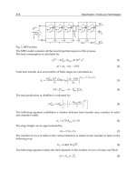
Consider the active vibration control system shown in Fig. 32.20. A mass m is sup-
ported by a spring of stiffness k, with a damping coefficient c. Force F is slowly
applied to the mass, as illustrated, causing the spring to stretch, resulting in a down-
ward displacement δ of the mass. A sensor responds to the displacement, causing it
to generate a signal proportional to the relative motion of the system. As a result,
power is supplied by a servo-controlled motor that moves the supporting frame
upward until the body returns to its original position with respect to the supporting
plane. This active vibration control system thus maintains the supported body in its
equilibrium position, despite the applied load, until another change in the force
occurs. Thus there is zero displacement of the mass in the presence of a constant
force F. This is a type of negative feedback regulation, so called because the servo-
controlled motor applies a “feedback” force to the supported body which opposes
its movement.A feedback control system is a system in which the value of some out-
put quantity is controlled by feeding back the value of the controlled quantity and
using it to manipulate an input quantity to bring the controlled quantity closer to the
desired value. (In contrast, a feedforward control system is a system in which changes
are detected at the process input, and anticipating correction is made before the
process output is affected.)
The active vibration isolation system illustrated in Fig. 32.20 seeks as its equilib-
rium position a location at a distance h above the reference lane of the support, inde-
SHOCK AND VIBRATION ISOLATORS AND ISOLATION SYSTEMS 32.29
8434_Harris_32_b.qxd 09/20/2001 12:32 PM Page 32.29
pendent of the origin and magnitude of
a steady force applied to the supported
body. While there is no change in the
position of the body in response to a
very slowly applied load, if the applied
load is suddenly removed, the servo-
mechanism (providing the regulation)
may be unable to respond fast enough to
compensate for the tendency of the sup-
ported body to change position relative
to the support; then the isolator can
experience a significant deflection.
This example demonstrates that
where the damped natural frequency of
the isolation system must be relatively
low, with the additional requirement
that the supported body be maintained
at a relatively constant distance from the
base to which it is attached, the applica-
tion of an active vibration control sys-
tem may be of considerable benefit.
Controller Gain; Integral Control; Pro-
portional Control. The computational
element for the elimination of the isola-
tor static deflection is that of an integra-
tor and scaling term called a controller
gain. This combination of sensing, computation, and actuation provides what is
known as integral control, since the feedback force is proportional to the time inte-
gral of the sensor response. The computational elements for the control of the sys-
tem resonance and low-frequency vibration isolation require only a scaling term.
This combination of control elements is called proportional control, since the feed-
back force is proportional to the sensor response. The feedback elements added to a
conventional isolation system must have an overall characteristic such that the out-
put force is proportional to the sensed function times the control function of the
computational element. The control function describes the operation of the compu-
tational element, which can be a simple constant as in proportional control, an inte-
gration function as in integral control, or an equation describing the action of one or
more electric circuits. This corresponds to a spring which provides an output force
proportional to the deflection of the spring, a viscous damper which provides a force
proportional to the rate of deflection of the damper, or an electric circuit which pro-
duces a force signal proportional to the dynamics of a spring and viscous damper, in
series, undergoing a motion proportional to the sensor response.
The sensing and actuation devices which provide integral control of the isolator
relative displacement may take many forms. For example, the sensing element which
measures the position of the supported body (relative to the reference plane of the
support) may be a differential transformer which produces an electrical signal pro-
portional to its extension relative to a neutral position. The sensing element is
attached at one end to the supported body and at the other end to the isolator sup-
port structure in a manner such that the sensor is in its neutral position when the
supported body is at its desired operating height. The electrical signal is integrated
and amplified in the computational element, providing electric power to operate an
32.30 CHAPTER THIRTY-TWO
FIGURE 32.20 Schematic diagram of an
active vibration-isolation system which main-
tains the supported body m a fixed distance h
from the reference plane of the support, irre-
spective of the steady force F applied to the sup-
ported body.
8434_Harris_32_b.qxd 09/20/2001 12:32 PM Page 32.30