- Trang chủ >>
- Khoa Học Tự Nhiên >>
- Vật lý
Chapter 9: Oscilator strengths and related topics doc
Bạn đang xem bản rút gọn của tài liệu. Xem và tải ngay bản đầy đủ của tài liệu tại đây (255.96 KB, 26 trang )
1
CHAPTER 9
OSCILLATOR STRENGTHS AND RELATED TOPICS
9.1 Introduction. Radiance and Equivalent Width.
If we look at a hot, glowing gas, we can imagine that we could measure its radiance in W m
-2
sr
-1
.
If we disperse the light with a spectrograph, we may see that it is made up of numerous discrete
emission lines. These lines are not infinitesimally narrow, but have a finite width and a measurable
profile. At any particular wavelength within the wavelength interval covered by the line, let us
suppose that the radiance per unit wavelength interval is I
λ
W m
-2
sr
-1
m
-1
. Here, we are using the
symbol I for radiance, which is customary in astronomy, rather than the symbol L, which we used
in chapter 1. We insist, however, on the correct use of the word "radiance", rather than the often
too-loosely used "intensity". We might imagine that we could measure I
λ
by comparing the
radiance per unit wavelength interval in the spectrum of the gas with the radiance per unit
wavelength interval of a black body at a known temperature (or of any other body whose emissivity
is known), observed under the same conditions with the same spectrograph.
The radiance I of the whole line is given by .λ=
∫
λ
dII In principle, the integration limits are 0
and
∞, although in practice for most lines the integration need be performed only within a few
tenths of a nanometre from the line centre.
The radiance of an emission line depends, among other things, upon the number of atoms per unit
area in the line of sight (the "column density") in the initial (i.e. upper) level of the line.
You will have noticed that I wrote "depends upon", rather than "is proportional to". We may
imagine that the number of atoms per unit area in the line of sight could be doubled either by
doubling the density (number of atoms per unit volume), or by doubling the depth of the layer of
gas. If doubling the column density results in a doubling of the radiance of the line, or, expressed
otherwise, if the radiance of a line is linearly proportional to the column density, the line is said to
be optically thin. Very often a line is not optically thin, and the radiance is not proportional to the
number of atoms per unit area in the upper level. We shall return to this topic in the chapter on the
curve of growth. In the meantime, in this chapter, unless stated otherwise, we shall be concerned
entirely with optically thin sources, in which case
,
2
N
∝
I where N is the column density and
the subscript denotes the upper level. We shall also suppose that the gas is homogenous and of a
single, uniform temperature and pressure throughout.
In the matter of notation, I am using:
n = number of atoms per unit volume
N = column density
N = number of atoms
2
Thus in a volume V, N = nV, and in a layer of thickness t,
N = nt.
Most lines in stellar spectra are absorption lines seen against a brighter continuum. In an
analogous laboratory situation, we may imagine a uniform layer of gas seen against a continuum.
We'll suppose that the radiance per unit wavelength interval of the background continuum source is
I
λ
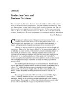
(c). We shall establish further notation by referring to figure IX.1, which represents an
absorption line against a continuum. The radiance per unit wavelength interval is plotted against
wavelength horizontally.
I
λ
(λ) is the radiance per unit wavelength interval at some wavelength within the line profile, and
I
λ
(λ
0
) is the radiance per unit wavelength interval at the line centre.
The equivalent width W (die Äquivalentbreite) of an absorption line is the width of the adjacent
continuum that has the same area as is taken up by the absorption line. Expressed as a defining
equation, this means:
[
]
.)()c()c( λλ−∫=
λλλ
dIIWI
9.1.1
Again in principle the integration limits are 0 to ∞, although in practice a few tenths of a nanometre
will suffice. Equivalent width is expressed in nm (or in Å). It must be stressed that equivalent
width is a measure of the strength of an absorption line, and is in no way related to the actual width
(or full width at half minimum) of the line. In figure IX.1, the width W of the continuum has the
same area as the absorption line.
I
λ
λ
()
I
λ
(c)
I
λ
λ
()
0
W
3
In principle, the equivalent width could also be expressed in frequency units (Hz), via a defining
equation:
[
]
.)()c()c(
)(
νν−∫=
ννν
ν
dIIIW 9.1.2
This is sometimes seen in theoretical discussions, but in practice equivalent width is usually
expressed in wavelength units. The two are related by
W
c
WW
c
W
() () () ()
,.
νλλ ν
λ
ν
==
22
9.1.3
Unless otherwise specified, I shall omit the superscript (λ), and W will normally mean equivalent
width expressed in wavelength units, as in equation 9.1.1.
Problem. A layer of cool gas lies above an extended source of continuous radiation, and an
absorption line formed in the gas layer has an equivalent width W. If the temperature of the
extended continuous source is now increased so that its spectral radiance at the wavelength of the
line is doubled, what will now be the equivalent width of the line?
The equivalent width of an absorption line depends, among other things, upon the number of
atoms per unit area in the line of sight (the "column density") in the initial (i.e. lower) level of the
line. If the gas is optically thin, W
∝
N
1
, where the subscript indicates the lower level of the
line.
If the absorption coefficient at wavelength
λ is α(λ) and has the same value throughout the gas, and
it the thickness of the gas layer is t, I
λ
(λ) and I
λ
(c) are related by
II t
λλ
λ
α
λ
( ) ( ) exp ( ) .
=
−
c 9.1.4
Thus equation 9.1.1 can be written
(
)
[
]
,)(exp1 λλα−−∫= dtW 9.1.5
and this equation is sometimes cited as the definition of the equivalent width. The definition,
however, is equation 9.1.1. Equation 9.1.4 can be used to calculate it, but only if α(λ) is uniform
throughout the gas. In the optically thin limit, the first term in the Maclaurin expansion of
()
t)(exp1 λα−− is α(λ)t, so that, for an optically thin homogeneous gas,
.)( λλα∫= dtW 9.1.6
The reader should verify, as ever, the dimensional correctness of all of the foregoing equations.
4
We have seen that the radiance of an emission line or the equivalent width of an absorption line
depends, among other things, on the column density of atoms in the initial state. In fact, in a
homogeneous optically thin gas, the radiance or equivalent width is linearly proportional to the
product of two things. One is the column density of atoms in the initial state. The other is an
intrinsic property of the atom, or rather of the two atomic levels involved in the formation of the
line, which determines how much energy a single atom emits or absorbs. There are three quantities
commonly used to describe this property, namely oscillator strength, Einstein coefficient and line
strength.
All three of these quantities are related by simple equations, but oscillator strength is particularly
appropriate when discussing absorption lines, Einstein coefficient is particularly appropriate when
discussing emission lines, while line strength is a quantum mechanical quantity particularly useful
in theoretical work. Because of this very technical usage of the term line strength, the term should
not be used merely to describe how "intense" a particular line appears to be.
9.2
Oscillator Strength. (die Oszillatorenstärke)
The concept of oscillator strength arises from a classical electromagnetic model of the absorption
of radiation by an atom. While a detailed understanding of each step in the derivation requires an
understanding and recall of some results from classical mechanics and electromagnetic theory, it is
not at all difficult to understand qualitatively the meaning of oscillator strength and at least the
general gist of the argument that follows.
An atom consists of a nucleus surrounded by electrons - but not all of the electrons are equally
strongly bound. We are going to think of an atom as having, for the purposes of this model, just
two parts of interest, namely an outer loosely bound electron, and the rest of the atom. If this
system is set into vibration, we'll suppose that it has a natural frequency ω
0
, but that the oscillations
are damped. An oscillating dipole does, of course, radiate electromagnetic waves. That is to say, it
loses energy. That is to say, the oscillations are damped. If the atom is placed in an oscillating
electric field (i.e. if you shine a light on the atom) given by ,cos
ˆ
tE ω the electron will experience a
force per unit mass
.cos
ˆ
t
m
Ee
ω
The equation of motion is
.cos
ˆ
2
0
t
m
Ee
xxx ω=ω+γ+
&&&
9.2.1
This is the differential equation that describes forced, damped oscillations. The solutions to this
equation are well known, but I shall defer detailed consideration of it until the chapter on line
profiles. Suffice it to say, for our present purposes, that it is possible to determine, from analysis of
this equation, how much energy is absorbed.
5
If a periodic force is applied to a mass attached to a fixed point by a spring, and the motion is
damped, either by viscous forces (for example, if the mass were immersed in a fluid) or by internal
stresses in the spring, not all of the work done by the periodic force goes into setting the mass in
motion; some of it is dissipated as heat. In a way, we are imagining the atom to consist of an
electron attached by some sort of force to the rest of the atom; not all of the work done by the
forcing electromagnetic wave goes into setting the electron in motion. Some of the work is
absorbed or degraded into a non-mechanical form. Perhaps the energy is lost because the
accelerating electron radiates away energy into space. Or perhaps, if you believe in discrete energy
levels, the atom is raised to a higher energy level. It does not matter a great deal what you believe
happens to the energy that is "lost" or "absorbed"; the essential point for the present is that
equation 9.2.1 allows us to calculate (and I do promise to do this in the chapter on line profiles) just
how much energy is lost or absorbed, and hence, if the atom is irradiated by a continuum of
wavelengths, it enables us to calculate the equivalent width of the resulting spectrum line. The
result obtained is
.
4
2
0
22
mc
e
W
ε
λ
=
N
9.2.2
W
= equivalent width in wavelength units.
N = column density (number per unit area in the line of sight) of absorbing atoms.
λ = wavelength of the line.
ε
0
= permittivity of free space.
e, m = charge and mass of the electron.
c = speed of light.
The reader should, as ever, check that the above expression has the dimensions of length. If every
quantity on the right hand side is expressed in SI units, the calculated equivalent width will be in
metres.
The reader may well object that s/he is not at all satisfied with the above argument. An atom is
not at all like that, it will be said. Besides, equation 9.2.2 says that the equivalent width depends
only on the wavelength, and that all lines of the same wavelength have the same equivalent width.
This is clearly nonsense. Let us deal with these two objections in turn.
First: Atoms are not at all like that. For a start, an atom is an entity that can exist only in certain
discrete energy levels, and the only atoms that will absorb radiation of a given frequency are those
that are in the lower level of the two levels that are involved in a line. Thus
N in equation 9.2.2
must be replaced by
N
1
, the column density (number per unit area in the line of sight) of just those
atoms that are in the lower level of the line involved. Thus equation 9.2.2 should be replaced by
.
4
2
0
22
1
mc
e
W
ε
λ
=
N
9.2.3
Second: The equivalent width of a line obviously does not depend only on its wavelength. Many
lines of very nearly the same wavelength can have almost any equivalent width, and the equivalent
6
width can vary greatly from line to line. We therefore now come to the definition of oscillator
strength
:
The absorption oscillator strength f
12
of a line is the ratio of its observed equivalent width to the
equivalent width (wrongly) predicted on the basis of the classical oscillator model and given by
equation 9.2.3.
Thus the expression for the equivalent width becomes
.
4
2
0
22
121
mc
ef
W
ε
λ
=
N
9.2.4
The oscillator strength for a given line must be determined either experimentally or theoretically
before the column density of a particular atom in, for example, a stellar spectrum can be
determined from the observed equivalent width of a line. In principle, the oscillator strength of a
line could be measured in the laboratory if one were able, for example, to measure the equivalent
width of a line produced in an absorbing gas in front of a continuum source, and if one were able
independently to determine
N
1
. Other experimental methods can be devised (see section 9.3 on
Einstein coefficients), and theoretical methods are also available (see section 9.5 on line strengths).
It should be emphasized that equation 9.2.4 applies only to an optically thin layer of gas. As far
as I can see, there is no reason why equation 9.2.4 is restricted either to a homogeneous layer of gas
of uniform temperature and pressure, or to a gas in thermodynamic equilibrium - but it does require
the layer to be optically thin.
We shall now restrict ourselves to an optically thin layer that is in thermodynamic equilibrium
and of uniform temperature throughout. In that case,
N
1
is given by Boltzmann's equation (see
equation 8.4.18):
.
)/(
11
1
u
kTE−
ϖ
=
e
N
N
9.2.5
Here N is the total number of atoms per unit area in all levels, ϖ
1
is the statistical weight 2J + 1 of
the lower level, and u is the partition function. Thus equations 9.2.4 and 9.2.5 combined become
.
4
2
0
)/(
121
22
1
umc
fe
W
kTE
ε
ϖλ
=
−
eN
9.2.6
In the above equations I have used slightly different fonts for e, the electronic charge, and
e, the
base of natural logarithms.
The quantity f
12
is called the absorption oscillator strength. An emission oscillator strength f
21
can
be defined by
7
ϖ
ϖ
112 2 21
f
f
=
, 9.2.7
and either side of this equation is usually given the symbol ϖf. Indeed, it is more usual to tabulate
the quantity ϖf than f
12
or f
21
alone. I should also point out that the notation seen in the literature
is very often gf rather than ϖf. However, in chapter 7 I went to considerable trouble to distinguish
between statistical weight, degeneracy and multiplicity, and I do not wish to change the notation
here. In any case, the value of ϖ (a form of the Greek letter pi) for an atomic energy level is 2J+1.
(We pointed out in chapter 7 why it is not usually necessary to include the further factor 2I + 1 for
an atom with nonzero nuclear spin.) Equation 9.2.6 is usually written
.
4
2
0
)/(
22
1
umc
fe
W
kTE
ε
ϖλ
=
−
eN
9.2.8
If we take the common logarithm of equation 9.2.8, we obtain
.log loglog
4
loglog
1
2
0
2
2
e
kT
eV
u
mc
e
f
W
−−+
ε
=
λϖ
N 9.2.9
If everything is in SI units, this is
.loglog053.14log
1
2
Vu
f
W
θ−−+−=
λϖ
N 9.2.10
I'd be happy for the reader to check my arithmetic here, and let me know ()
if it's not right. Here W and λ are to be expressed in metres and N
in atoms per square metre. V
1
is the excitation potential of the lower level of the line in volts, and θ is 5039.7/T, where T is the
excitation temperature in kelvin. Thus, if we measure the equivalent widths of several lines from
an optically thin gas, and plot
λϖ
2
log
f
W
versus the excitation potential of the lower level of each
line, we should get a straight line whose slope will give us the excitation temperature, and,
provided that we know the partition function, the intercept will give us the column density of the
neutral atoms (in all levels) or of a particular ionization state.
Often it will happen that some points on the graph fall nowhere near the regression line. This could
be because of a wildly-erroneous oscillator strength, or because of a line misidentification.
Sometimes, especially for the resonance lines (the strongest lines arising from the lowest level or
term) a line lies well below the regression line; this may be because these lines are not optically
thin. Indeed, equation 9.2.10 applies only for optically thin lines.
Equation 9.2.10 shows how we can make use of Boltzmann’s equation and plot a straight-line
graph whose slope and intercept will give us the excitation temperature and the column density of
8
the atoms. We can go further and make use of Saha’s equation. If we plot
λϖ
2
log
f
W
versus the
lower excitation potential for atomic lines and do the same thing separately for ionic lines, we
should obtain two straight lines of the same slope (provided that the gas is in thermodynamic
equilibrium so that the excitation temperatures of atom and ion are the same). From the difference
between the intercepts of the two lines we can get the electron density. Here’s how it works.
If we set up equation 9.2.9 or equation 9.2.10 for the atomic lines and for the ionic lines, we see
that the difference between the intercepts will be equal to
ai
ia
u
u
N
N
log
, and, if the gas is optically
thin, this is also equal to
.log
ai
ia
un
un
Here the subscripts denote atom and ion, N is column density
and n is particles per unit volume. Then from equation 8.6.7 we see that
ai
ia
un
un
log
= difference between intercepts =
(
)
.loglog24.27
2
3
e
nVV −∆
−
θ
−
θ
−
9.2.11
Here θ is 5039.7/T, where T is the ionization temperature and, in assuming that this is the same as
the excitation temperatures obtained from the slopes of the lines, we are assuming thermodynamic
equilibrium. V is the ionization potential of the atom. Thus we can obtain the electron density n
e
–
except for one small detail. ∆V is the lowering of the excitation potential, which itself depends on
n
e
. We can first assume it is zero and hence get a first approximation for n
e
; then iterate to get a
better V in the same manner that we did in solving Problem 4 of section 8.6.
So far we have discussed the equivalent width of a line. A line, however, is the sum of several
Zeeman components, with (in the absence of an external magnetic field) identical wavelengths. It
is possible to define an oscillator strength of a Zeeman component. Is the oscillator strength of a
line equal to the sum of the oscillator strengths of its components? The answer is no. Provided the
line and all of its components are optically thin, the equivalent width of a line is equal to the sum of
the equivalent widths of its components. Thus equation 9.2.8 shows that the ϖf value of a line is
equal to the sum of the ϖf values of its components. A further point to make is that, for a
component, the statistical weight of each state of the component is unity. (A review from chapter 7
of the meanings of line, level, component, state, etc., might be in order here.) Thus, for a
component there is no distinction between absorption and emission oscillator strength, and one can
use the isolated symbol f with no subscripts, and the unqualified phrase "oscillator strength"
(without a "absorption" or "emission" prefix) when discussing a component. One can accurately
say that the ϖf value of a line is equal to the sum of the f values of its components. In other words,
ϖf(line) = Σf(components), so that one could say that the oscillator strength of a line is the average
of the oscillator strength of its components. Of course, this doesn't tell you, given the ϖf value of a
line, what the f-values of the individual components are. We defer discussion of that to a later
section of this chapter.
9
The phrase "f-value" is often used instead of "oscillator strength". I was rather forced into that in
the previous paragraph, when I needed to talk about ϖf values versus f-values. However, in
general, I would discourage the use of the phrase "f-value" and would encourage instead the phrase
"oscillator strength". After all, we never talk about the "e-value" of the electron or the "M-value"
of the Sun. I suppose "weighted oscillator strength" could be used for ϖf.
9.3
Einstein A Coefficient
Although either oscillator strength or Einstein A coefficient could be used to describe either an
emission line or an absorption line, oscillator strength is more appropriate when talking about
absorption lines, and Einstein A coefficient is more appropriate when talking about emission lines.
We think of an atom as an entity that can exist in any of a number of discrete energy levels. Only
the lowest of these is stable; the higher levels are unstable with lifetimes of the order of
nanoseconds. When an atom falls from an excited level to a lower level, it emits a quantum of
electromagnetic radiation of frequency ν given by
h
E
ν
=
∆
, 9.3.1
where
∆
E
E
E
=−
21
, E
2
and E
1
respectively being the energies of the upper (initial ) and lower
(final) levels. The number of downward transitions per unit time is supposed to be merely
proportional to the number of atoms, N
2
, at a given time in the upper level. The number of
downward transitions per unit time is
22
since, NN
&&
− in calculus means the rate at which N
2
is
increasing. Thus
.
2212
NAN =−
&
9.3.2
The proportionality constant A
21
is the Einstein coefficient for spontaneous emission for the
transition from E
2
to E
1
. It is equivalent to what, in the study of radioactivity, would be called the
decay constant, usually given the symbol λ. It has dimensions T
-1
and SI units s
-1
. Typically for
electric dipole transitions, it is of order 10
8
s
-1
. As in radioactivity, integration of the above
equation shows that if, at time zero, the number of atoms in the upper level is N
2
(0), the number
remaining after time t will be
Nt N
At
22
0
21
() () .
=
−
e
9.3.3
Likewise, as will be familiar from the study of radioactivity (or of first-order chemical reactions, if
you are a chemist), the mean lifetime in the upper level is 1/A
21
and the half-life in the upper level
is (ln 2)/A
21
. This does presume, however, that there is only one lower level below E
2
. We return
to this point in a moment, when we consider the situation when there is a choice of more than one
lower level to which to decay from E
2
.
10
Since there are A
21
N
2
downward transitions per units time from E
2
to E
1
, and each transition is
followed by emission of an energy quantum hν, the rate of emission of energy from these N
2
atoms,
i.e. the radiant power or radiant flux (see chapter 1) is
Φ
=
N
Ahv
221
watts. 9.3.4
(For absolute clarity, we could append the subscript 21 to the frequency ν in order to make clear
that the frequency is the frequency appropriate to the transition between the two energy levels; but
a surfeit of subscripts might be too distracting to the point of actually making it less clear.)
Provided the radiation is emitted isotropically, the intensity is
I
N
A
h
=
221
4
ν
π
W sr
-1
. 9.3.5
The emission coefficient (intensity per unit volume) is
j
nAh
=
221
4
ν
π
W m
-3
sr
-1
. 9.3.6
If we are looking at a layer, or slice, or slab, of gas, the radiance is
.
4
212
π
ν
hA
L
N
= W m
-2
sr
-1
. 9.3.7
Here, I have been obliged to use I and L correctly for intensity and radiance, rather than follow the
unorthodox astronomical custom of using I for radiance and calling it "intensity". I hope that, by
giving the SI units, I have made it clear, though the reader may want to refer again to the
definitions of the various quantities described in chapter 1. I am using the symbols described in
section 9.1 of the present chapter for N, n and N
. I should also point out that equations 9.3.4-7
require the gas to be optically thin.
Equation 9.3.2 and 3 assume that the atom, starting from level 2, can decay to only one lower level.
This may sometimes be the case, or, even if it is not, transitions to one particular lower level are far
more likely than decay to any or all of the others. But in general, there will be a choice (with
different branching ratios) of several lower levels. The correct form for the decay constant under
those circumstances is λ=
∑
A
21
, the sum to be taken over all the levels below E
2
to which the
atom can decay, and the mean lifetime in level 2 is 1
21
/.A
∑
Nowadays it is possible to excite a
particular energy level selectively and follow electronically on a nanosecond timescale the rate at
which the light intensity falls off with time. This tells us the lifetime (and hence the sum of the
relevant Einstein coefficients) in a given level, with great precision without having to measure
absolute intensities or the number of emitting atoms. This is a great advantage, because the
measurement of absolute intensities and determination of the number of emitting atoms are both
matters of great experimental difficulty, and are among the greatest sources of error in laboratory
determinations of oscillator strengths. The method does not by itself, however, give the Einstein
coefficients of individual lines, but only the sum of the Einstein coefficients of several possible
11
downward transitions. Measurements of (or theoretical calculations of) relative oscillator
strengths or branching ratios (which do not require absolute intensity measurements or
determinations of the number of emitting or absorbing atoms), combined with lifetime
measurements, however, can result in relatively reliable absolute oscillator strengths or Einstein
coefficients.
We shall deal in section 9.4 with the relation between oscillator strength and Einstein coefficient.
If the optically thin layer of gas described by equation 9.3.7 is in thermodynamic equilibrium, then
N
2
is given by Boltzmann's equation, so that equation 9.3.7 becomes
.
4
)/(
212
2
u
Ahc
L
kTE
πλ
ϖ
=
−
eN
9.3.8
The common logarithm of this is
.logloglog
4
loglog
2
212
e
kT
eV
u
hc
A
L
−−+
π
=
ϖ
λ
N 9.3.9
If everything is in SI units, this becomes
.loglog801.25log
2
212
Vu
A
L
θ−−+−=
ϖ
λ
N
9.3.10
Thus a graph of
ϖ
λ
212
log
A
L
versus the upper excitation potential V
2
will yield (for optically
thin lines) the temperature and the column density of atoms from the slope and intercept. I leave it
to the reader to work out the procedure for determining the electron density in a manner similar to
how we did this for absorption lines in developing equation 9.2.11.
The radiance of a line is, of course, the sum of the radiances of its Zeeman components, and, since
the radiance is proportional to ϖ
2
A
21
, one can say, following a similar argument to that given in the
penultimate paragraph of section 9.2, that the Einstein coefficient of a line is equal to the average
of the Einstein coefficients of its components.
At this stage, you may be asking yourself if there is a relation between oscillator strength and
Einstein coefficient. There is indeed, but I crave your patience a little longer, and I promise to
address this in section 9.4.
12
“Transition Probability” (die Übergangswahrscheinlichkeit.) The expression “transition
probability” is often used for the Einstein A coefficient, and it is even sometimes defined as “the
probability per second that an atom will make a spontaneous downward transition from level 2 to
level 1”. Both are clearly wrong.
In probability theory (especially in the theory of Markov chains) one sometimes has to consider a
system that can exist in any of several states (as indeed an atom can) and the system, starting from
one state, can make a transition to any of a number of other possible states. The probability of
making a particular transition is called, not unnaturally, the transition probability. The transition
probability so defined is a dimensionless number in the range zero to one inclusive. The sum of the
transition probabilities to all possible final states is, of course unity. “Branching ratio” is another
term often used to describe this concept, although perhaps “branching fraction” might be better. In
any case, the reader must be aware that in many papers on spectroscopy, the phrase “transition
probability” is used when what is intended is the Einstein A coefficient.
The reader will have no difficulty in showing (from equation 9.3.3) that the probability that an
atom, initially in level 2, will make a spontaneous downward transition to level 1 in time t, is
tA
e
21
1 − , and that the probability that it will have made this transition in a second is .1
21
A
e
−
−
With A
21
being typically of order 10
8
s
-1
, this probability is, unsurprisingly, rather close to one!
9.4
Einstein B Coefficient
In section 9.2 on oscillator strengths, we first defined what we meant by absorption oscillator
strength f
12
. We then showed that the equivalent width of a line is proportional to ϖ
1
f
12
. We
followed this by defining an emission oscillator strength f
21
by the equation ϖ
2
f
21
= ϖ
1
f
12
.
Thereafter we defined a weighted oscillator strength ϖf to be used more or less as a single symbol
equal to either ϖ
2
f
21
or ϖ
1
f
12
. Can we do a similar sort of thing with Einstein coefficient? That is,
we have defined A
21
, the Einstein coefficient for spontaneous emission (i.e. downward transition)
without any difficulty, and we have shown that the intensity or radiance of an emission line is
proportional to ϖ
2
A
21
. Can we somehow define an Einstein absorption coefficient A
12
? But this
would hardly make any sense, because atoms do not make spontaneous upward transitions! An
upward transition requires either absorption of a photon or collision with another atom.
For absorption lines (upwards transitions) we can define an Einstein B coefficient such that the rate
of upward transitions from level 1 to level 2 is proportional to the product of two things, namely
the number of atoms N
1
currently in the initial (lower) level and the amount of radiation that is
available to excite these upward transitions. The proportionality constant is the Einstein coefficient
for the transition, B
12
. There is a real difficulty in that by “amount of radiation” different authors
mean different things. It could mean, for example, any of the four things:
u
λ
the energy density per unit wavelength interval at the wavelength of the line, expressed
in J m
-3
m
-1
;
u
ν
the energy density per unit frequency interval at the frequency of the line, expressed in
J m
-3
Hz
-1
;
13
L
λ
radiance (unorthodoxly called “specific intensity” or even merely “intensity” and given
the symbol I by many astronomers) per unit wavelength interval at the wavelength
of the line, expressed in W m
-2
sr
-1
m
-1
;
L
ν
radiance per unit frequency interval at the frequency of the line, expressed in W m
-2
sr
-1
Hz
-1
.
Thus there are at least four possible definitions of the Einstein B coefficient and it is rarely clear
which definition is intended by a given author. It is essential in all one’s writings to make this clear
and always, in numerical work, to state the units. If we use the symbols
dcba
BBBB
12121212
,,, for these
four possible definitions of the Einstein B coefficient, the SI units and dimensions for each are
a
B
12
: s
-1
(J m
-3
m
-1
)
-1
M
−1
L
2
T
b
B
12
: s
-1
(J m
-3
Hz
-1
)
-1
M
−1
L
c
B
12
: s
-1
(W m
-2
sr
-1
m
-1
)
-1
M
−1
L T
2
d
B
12
: s
-1
(W m
-2
sr
-1
Hz
-1
)
-1
. M
−1
T
You can, of course, find equivalent ways of expressing these units (for example, you could express
b
B
12
in metres per kilogram if you thought that that was helpful!), but the ones given make crystal
clear the meanings of the coefficients.
The relations between them are (omitting the subscripts 12):
dcba
BB
c
B
c
B
π
λ
=
π
=
λ
=
44
22
; 9.4.1
adcb
B
c
B
c
BB
22
44
ν
=
π
=
π
ν
= ; 9.4.2
badc
B
c
B
c
B
c
B
2
22
44 πλ
=
π
=
λ
= ; 9.4.3
cbad
B
c
B
c
B
c
B
2
2
2
44 ν
=
π
=
πν
= ; 9.4.4
14
For the derivation of these, you will need to refer to equations 1.3.1, 1.15.3 and 1.17.12,
From this point henceforth, unless stated otherwise, I shall use the first definition without a
superscript, so that the Einstein coefficient, when written B
12
,
will be understood to mean .
12
a
B Thus
the rate of radiation-induced upward transitions from level 1 to level 2 will be taken to be B
12
times
N
1
times u
λ
.
Induced downward transitions.
The Einstein B
12
coefficient and the oscillator strength f
12
(which are closely related to each other
in a manner that will be shown later this section) are concerned with the forced upward transition
of an atom from a level 1 to a higher level 2 by radiation of a wavelength that corresponds to the
energy difference between the two levels. The Einstein A
21
coefficient is concerned with the
spontaneous downward decay of an atom from a level 2 to a lower level 1.
There is another process. Light of the wavelength that corresponds to the energy difference
between levels 2 and 1 may induce a downward transition from an atom, initially in level 2, to the
lower level 1. When it does so, the light is not absorbed; rather, the atom emits another photon of
that wavelength. Of course the light that is irradiating the atoms induces upward transitions from
level 1 to level 2, as well as inducing downward transitions from level 2 to level 1, and since, for
any finite positive temperature, there are more atoms in level 1 than in level 2, there is a net
absorption of light. (The astute leader will note that there may be more atoms in level 2 than in
level 1 if it has a larger statistical weight, and that the previous statement should refer to states
rather than levels.) If, however, the atoms are not in thermodynamic equilibrium and there are
more atoms in the higher levels than in the lower (the atom is “top heavy”, corresponding to a
negative excitation temperature), there will be Light Amplification by Stimulated Emission of
Radiation (LASER). In this section, however, we shall assume a Boltzmann distribution of atoms
among their energy levels and a finite positive excitation temperature. The number of induced
downward transitions per unit time from level 2 to level 1 is given by B
21
N
2
u
λ
. Here B
21
is the
Einstein coefficient for induced downward transition.
Let m denote a particular atomic level. Let n denote any level lower than m and let
'n denote any
level higher than m. Let N
m
be the number of atoms in level m at some time. The rate at which N
m
decreases with time as a result of these processes is
.
'
'
'
mnmn
uBNuBNANN
n
mnm
n
mnm
n
mnmm
λλ
∑
∑
∑
++=−
&
9.4.5
This equation describes only the rate at which
m
N is depleted by the three radiative processes. It
does not describe the rate of replenishment of level m by transitions from other levels, nor with its
depletion or replenishment by collisional processes. Equation 9.4.5 when integrated results in
.)0()(
t
mm
m
eNtN
Γ−
=
9.4.6
15
Here
'
'
'
mnmn
uBuBA
n
mn
n
mn
n
mnm
λλ
∑
∑
∑
++=Γ 9.4.7
(Compare equation 9.3.3, which dealt with a two-level atom in the absence of stimulating
radiation.)
The reciprocal of Γ
m
is the mean lifetime of the atom in level m.
Consider now just two levels – a level 2 and a level below it, 1. The rate of spontaneous and
induced downward transitions from m to n is equal to the rate of forced upward transitions from n
to m:
λλ
=
+ uNBuNBNA
112221221
. 9.4.8
I have omitted the subscripts 21 to λ, since there in only one wavelength involved, namely the
wavelength corresponding to the energy difference between the levels 2 and1. Let us assume that
the gas and the radiation field are in thermodynamic equilibrium. In that case the level populations
are governed by Boltzmann’s equation (equation 8.4.19), so that equation 9.4.8 becomes
()
,
)/(
0
1
012
)/(
0
2
02121
12
kTEkTE
eNuBeNuBA
−
λ
−
λ
ϖ
ϖ
=
ϖ
ϖ
+ 9.4.9
from which
,
221
)/(
112
221
ϖ−ϖ
ϖ
=
λ
λ
BeB
A
u
kThc
9.4.10
where I have made use of
./
12
λ
=− hcEE 9.4.11
Now, still assuming that the gas and photons are in thermodynamic equilibrium, the radiation
distribution is governed by Planck’s equation (equations 2.6.4, 2.6.5, 2.6.9; see also equation
2.4.1):
()
.
1
8
)/(5
−λ
π
=
λ
λ
kThc
e
hc
u 9.4.12
On comparing equations 9.4.10 and 9.4.12, we obtain
.
8
212
5
212121
A
hc
BB ϖ
π
λ
=ϖ=ϖ 9.4.13
16
A reminder here may be appropriate that the B here is B
a
as defined near the beginning of this
section. Also, in principle there would be no objection to defining an
Bϖ such that
212121
BBB ϖ=ϖ=ϖ , just as was done for oscillator strength, although I have never seen this
done.
Einstein B
12
coefficient and Equivalent width.
Imagine a continuous radiant source of radiance per unit wavelength interval L
λ
, and in front of it
an optically thin layer of gas containing
N
1
atoms per unit area in the line of sight in level 1. The
number of upward transitions per unit area per unit time to level 2 is
12
112
λ
LB
c
N , and each of these
absorbs an amount hc/λ
12
of energy. The rate of absorption of energy per unit area per unit solid
angle is therefore
.
4
1
12
112
12
λπ
λ
hc
LB
c
×× N
This, by definition of equivalent width (in wavelength
units), is equal to
12
λ
WL .
Therefore
.
4
121
1212
112
a
c
B
hhcB
W N
N
λπλ
== 9.4.14
If we compare this with equation 9.2.4 we obtain the following relation between
a
B
12
and f
12
:
.
4
12
2
0
32
12
f
hmc
e
B
a
ε
λ
= 9.4.15
It also follows from equations 9.4.13 and 9.4.15 that
.
2
121
2
0
2
212
f
mc
e
A ϖ
λε
π
=ϖ 9.4.16
I shall summarize the various relations between oscillator strength, Einstein coefficient and line
strength in section 9.9.
9.5 Line Strength
The term line strength, although often loosely used to indicate how prominent or otherwise a
spectrum line is, has acquired in theoretical spectroscopy a rather definite specialist meaning,
which is discussed in this section.
In discussing the intensities of emission lines, the Einstein A is an appropriate parameter to use,
whereas in discussing the equivalent widths of absorption lines the appropriate parameter is
oscillator strength f. Either of these can be determined experimentally in the laboratory. The
17
Einstein coefficient and the oscillator strength are related (I summarize the relations in section 9.9)
and either could in principle be used whether discussing an emission or an absorption line.
In theoretical studies one generally uses yet another parameter, called the line strength.
The theoretical calculation of line strengths is a specialized study requiring considerable experience
in quantum mechanics, and is not treated in any detail here. Instead I give just a short qualitative
description, which I hope will be sufficient for the reader to understand the meaning of the term
line strength without actually being able to calculate it. Absolute line strengths can be calculated in
terms of explicit algebraic formulas (albeit rather long ones) for hydrogen-like atoms. For all
others, approximate numerical methods are used, and it is often a matter of debate whether
theoretically calculated line strengths are more or less preferable to experimentally determined
oscillator strengths, Einstein coefficients or lifetimes. As a general rule, the more complex the
atom, unsurprisingly the more difficult (and less reliable?) are the theoretical calculations, whereas
for light atoms theoretical line strengths may be preferable to experimental oscillator strengths.
Energy levels of atoms are found from the eigenvalues of the time-independent wave equation. For
the interaction of electromagnetic radiation with an atom, however, solutions of the time-dependent
equation are required. The effect of the electromagnetic radiation is to impose a time-dependent
perturbation on the wavefunctions. In the formation of permitted lines, the electromagnetic wave
interacts with the electric dipole moment of the atom. This is a vector quantity given by
ii
e r
∑
,
where
r
i
is the position vector of the ith electron in the atom. The expectation value of this quantity
over the initial (i)and final (f) states of a transition is
τψψ
∫
d
if
µ* , 9.5.1
or, as it is usually written
nLSJMMJSLn µ''''' . 9.5.2
Here, for permitted lines, µ is the electric dipole moment operator. For forbidden lines it is
replaced with either the magnetic dipole moment operator or the electric quadrupole moment
operator, or, in principle, moments of even higher order. In any case, the above quantity is called
the transition moment. In the case of electric dipole (permitted) lines, its SI unit is C m, although it
is more commonly expressed in units of a
0
e (“atomic unit”) or, in older literature, cgs esu, or, in
some chemical literature, debye.
1 debye = 10
-18
cgs esu = 0.3935 atomic units = 3.336 × 10
-30
C m
1 atomic unit = 8.478 ×10
-30
C m.
The square of the transition moment is called the line strength. Oscillator strengths and Einstein
coefficients of Zeeman components (i.e. of transitions between states) are proportional to their line
strengths, or to the squares of their transition moments. The symbol generally used for line
strength is S. Line strengths are additive. That is to say the strength of a line is equal to the sum of
18
the strengths of its Zeeman components. In this respect it differs from oscillator strength or
Einstein coefficient, in which the oscillator strength or Einstein coefficient of a line is equal to the
average oscillator strength of Einstein coefficient of its components. Furthermore, line strength is
symmetric with respect to emission and absorption, and there is no need for distinction between S
12
and S
21
. Intensities of emission lines are proportional to their line strengths S or to their weighted
Einstein coefficients ϖ
2
A
21
. Equivalent widths of absorption lines are proportional to their line
strengths or to their weighted oscillator strengths ϖ
1
f
12
.
I dwell no more on this subject in this section other than to state, without derivation, the relations
between Einstein coefficient and line strength. The formulas below, in which ε
0
and µ
0
are the
“rationalized” permittivity and permeability of free space, are valid for any coherent set of units; in
particular they are suitable for SI units.
For electric dipole radiation:
1E
3
0
3
212
3
16
S
h
A
λε
π
=ϖ . 9.5.3
For electric quadrupole radiation:
2E
5
0
5
212
5
8
S
h
A
λε
π
=ϖ . 9.5.4
For magnetic dipole radiation:
.
3
16
1M
3
0
3
212
S
h
A
λ
µπ
=ϖ 9.5.5
The subscripts E1, E2, M1 to the symbol S indicate whether the line strength is for electric dipole,
electric quadrupole or magnetic dipole radiation. Although I have not derived these equations, you
should check to see that they are dimensionally correct. The dimensional analysis will have to use
the four dimensions of electromagnetic theory, and you must note that the SI units for line strength
are C
2
m
2
, C
2
m
4
and A
2
m
4
for electric dipole, electric quadrupole and magnetic dipole radiation
respectively. Please let me know (
) if you find any discrepancies. In equation
9.5.5, µ
0
is the permeability of free space.
By making use of equation 9.4.16, we also find, for electric dipole radiation, that
.
3
8
1E
2
2
121
S
he
mc
ff
λ
π
=ϖ=ϖ 9.5.6
19
9.6
LS-coupling
The expression 9.5.2 gives the transition moment for a component, and its square is the strength of
the component. For the strength of a line, one merely adds the strengths of the components. In
general it is very hard to calculate the transition moment accurately in absolute units.
In LS-coupling, the strength of a line can be written as the product of three factors:
S =
S(M)S(L)σ
2
. 9.6.1
Here σ
2
is the strength of the transition array, and is given by
.
14
2
0
3
2
2
2
−
=
∫
∞
drRRr
l
e
fi
σ
9.6.2
Here l is the larger of the two azimuthal quantum numbers involved in the transition. R
i
and R
f
are
the radial parts of the initial and final wavefunctions (each of which has dimension L
-3/2
). The
reader should verify that the expression 9.6.2 has dimensions of the square of electric dipole
moment. In general σ
2
(which is the only dimensioned term on the right hand side of equation
9.6.1) is difficult to calculate, and it determines the absolute scale of the line strengths. Unless the
strength of the transition array can be determined (in C
2
m
2
or equivalently in atomic units of
a
0
2
e
2
), absolute values of line strengths will remain unknown. However, for LS-coupling, there
exist explicit algebraic expressions for
S(M), the relative strengths of the multiplets within the
array, and for
S(L), the relative strengths of the lines within a multiplet. In this section I give the
explicit formulas for the relative strengths of the lines within a multiplet.
In LS-coupling there are two types of multiplet – those in which L changes by 1, and those in which
L does not change. I deal first with multiplets in which L changes by 1. In the following formulas,
L is the larger of the two orbital angular momentum quantum numbers involved. For multiplets
connecting two LS-coupled terms, S is the same in each term. The selection rule for J is ∆J = 0,
±1. The lines in which J changes in the same way as L (i.e. if L increases by 1, J also increases by
1) are the strongest lines in the multiplet, and are called the main lines or the principal lines. The
lines in which J does not change are weaker (“satellite” lines), and the lines in which the change in
J is in the opposite sense to the change in L are the weakest (“second satellites”). Some of the
following formulas include the factor (−1)
2
. This is included so that the transition moment (the
square root of the line strength) can be recovered if need be.
Multiplet L to L − 1.
Main lines, J to J − 1:
)12)(14(4
))(1)()(1(
)L(
2
+−
+
+
+
+
+
−
+
−−+
=
SLJL
SLJSLJSLJSLJ
S 9.6.3
20
First satellites (weaker lines), no change in J:
)12)(14()1(4
))(1)(1)()(12(
)L(
2
+−+
+
+
−
+
+
+
+
+
−
−
++
=
SLLJJ
SLJSLJSLJSLJJ
S 9.6.4
Second satellites (weakest lines), J to J + 1:
)12)(14()1(4
)1)(2)()(1()1(
)L(
2
2
+−+
−++−++−++−++−−
=
SLLJ
SLJSLJSLJSLJ
S 9.6.5
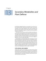
Example: The multiplet
3
P −
3
D. Here, we have S = 1, and L = 2.
There are six lines. In what follows I list them, together with the J value to be substituted in the
formulas, and the value of
S(L).
3
P
0
−
3
D
1
Main J = 1 S(L) = 1/9 = 0.11111
3
P
1
−
3
D
2
Main J = 2 S(L) = 1/4 = 0.25000
3
P
1
−
3
D
1
First satellite J = 1 S(L) = 1/12 = 0.08333
3
P
2
−
3
D
3
Main J = 3 S(L) = 7/15 = 0.46667
3
P
2
−
3
D
2
First satellite J = 2 S(L) = 1/12 = 0.08333
3
P
2
−
3
D
1
Second satellite J = 1 S(L) = 1/180 = 0.00556
The transitions and the positions and intensities of the lines are illustrated in figure IX.2. It was
mentioned in Chapter 7 that one of the tests for LS-coupling was Hund’s interval rule, which
governs the spacings of the levels within a term, and hence the wavelength spacings of the lines
within a multiplet. Another test is that the relative intensities of the lines within a multiplet follow
the line strength formulas for LS-coupling. The characteristic spacings and intensities form a
“fingerprint” by which LS-coupling can be recognized. It is seen in the present case (
3
P −
3
D)
that there are three main lines, the strongest of which has two satellites, and the second strongest
has one satellite.
21
.
Frequency
FIGURE IX.2
3
D
123
3
P
012
22
The second type of multiplet is the symmetric multiplet, in which there is no change in L − for
example,
3
P −
3
P. The strongest lines (main lines) are those in which there is no change in J.
The formulas for the relative line strengths within a symmetric multiplet are:
Main lines, no change in J:
)12)(12)(1()1(4
)]1()1()1()[12(
)L(
2
++++
+−++++
=
SLLLJJ
SSLLJJJ
S 9.6.6
Satellite lines, J changes by ±1; in the following formula, J is the larger of the two J-values:
)12)(12)(1(4
)1)(1)()(()1(
)L(
2
+++
+++−++++−−+−
=
SLLJL
SLJSLJSLJSLJ
S
9.6.7
Example:
3
D −
3
D:
3
D
1
−
3
D
1
Main J = 1 S(L) = 0.150000
3
D
2
−
3
D
2
Main J = 2 S(L) = 0.231481
3
D
3
−
3
D
3
Main J = 3 S(L) = 0.414815
3
D
2
−
3
D
3
Satellite J = 3 S(L) = 0.051852
3
D
1
−
3
D
2
Satellite J = 2
S(L) = 0.050000
3
D
3
−
3
D
2
Satellite J = 3 S(L) = 0.051852
3
D
2
−
3
D
1
Satellite J = 2 S(L) = 0.050000
I leave it to the reader to draw a figure analogous to figure IX.2 for a symmetric multiplet.
Remember that the spacings of the levels within a term are given by equation 7.17.1, and you can
use different coupling coefficients for the two terms. It should be easier for you to draw the levels
and the transitions with pencil and ruler than for me to struggle to draw it with a computer.
Tabulations of these formulae are available in several places. Today, however, it is often quicker to
calculate them with either a computer or hand calculator than to find one of the tabulations and
figure out how to read it. (Interesting thought: It is quicker to draw an energy level diagram with
pencil and paper than with a computer, but it is quicker to calculate line strengths by computer than
to look them up in tables.)
23
The relative strengths of hyperfine components within a line can be calculated with the same
formulae by substituting JIF for LSJ, since JI-coupling is usual.
9.7
Atomic hydrogen
What is meant by the oscillator strength of Hα? This question may well be asked, recalling that
Hα technically is not a single line, but consists of three transition arrays, three multiplets, seven
lines, and I don’t think we ever worked out quite how many Zeeman and hyperfine components.
The hydrogen atom is a two-body system, and for such a system the wavefunction and its
eigenvalues (energy levels) can be worked out explicitly in algebraic terms. The same is true of the
transition moments and hence the strengths of each Zeeman and hyperfine component. The
strength of the entire “line” of Hα is then merely the sum of the strengths of all the Zeeman and
hyperfine components of which it is composed. Then the weighted oscillator strength of Hα is
merely calculated from equation 9.5.6. As for the question: What is ϖ? – the question need not
arise, since all one is likely to need is the product ϖf. However if this has been worked out by
adding the strengths of all the Zeeman and hyperfine components, it would be 4n
2
, which, for the
lower level of Hα, is 8.
For the record, here are the weighted oscillator strengths, ϖf, for the first four “lines” of the Lyman
and Balmer series for H.
Lyman Balmer
α 0.555 3.139
β 0.105 0.588
γ 0.0387 0.220
δ 0.0186 0.103
9.8
Zeeman components
In this section I give
S(C), the relative strengths of Zeeman components within a line.
I consider first lines for which J changes by 1, and then lines for which J does not change.
Lines connecting J to J − 1.
Components connecting M to M − 1:
()
(
)
<>
+
+= MJMJ)C(S 9.8.1
24
Components connecting M to M+1:
()
(
)
.)C(
><
−
−= MJMJS 9.8.2
Components in which M does not change:
).)((4)C( MJMJ
−
+=S 9.8.3
In these equations J is the larger of the two J-values involved in the line;
>
M and
<
M are,
respectively, the larger and the smaller of the two M-values involved in the component. Note that
these formulas are not normalized to a sum of unity. In order to do so, the strength of each
component should be divided by the sum of the strengths of all the components – i.e. by the
strength of the line.
Example. Consider the Zeeman pattern of figure VII.1. The strength factors for each of the nine
components, reading from left to right in the figure, will be found to be
0 2 6 12 16 12 6 2 0
Normalized to unity, these are
0.0000 0.0357 0.1071 0.2143 0.2857 0.2143 0.1071 0.0357 0.0000
As described in section 7.27 in connection with figure VII.1, the components within each group of
three are unresolved, so the relative strengths of the three groups are
7
1
7
5
7
1
.
Consider also the Zeeman pattern of figure VII.2. The strength factors for each of the six
components, reading from left to right in the figure, will be found to be
2 6 8 8 6 2,
or, normalized to unity,
.
16
1
16
3
16
4
16
4
16
3
16
1
Lines for which J does not change.
Components for which M changes by ±1
(
)
(
)
.)C(
><
−
+
= MJMJS 9.8.4
Components for which M does not change:
25
.4)C(
2
M=S 9.8.5
Example. For a line J − J = 2 − 2, the relative strengths of the components are
M′ M″
S(C)
-2 -2 16
-2 -1 4
-1 -2 4
-1 -1 4
-1 0 6
0 -1 6
0 0 0
0 1 6
1 0 6
1 1 4
1 2 4
2 1 4
2 2 16
9.9
Summary of Relations Between f, A and S.
In this section I use ϖf to mean either ϖ
1
f
12
or ϖ
2
f
21
, since these are equal; likewise I use ϖB to
mean either ϖ
1
B
12
or ϖ
2
B
21
. The Einstein A coefficient is used exclusively in connection with
emission spectroscopy. The B coefficient is defined here in terms of radiation energy density per
unit wavelength interval; that is, it is the B
a
of section 9.4. The relations between the possible
definitions of B are given in equations 9.4.1-4.
The following relations for electric dipole radiation may be useful. In these, ε
0
is the “rationalized”
definition of free space permittivity, and the formulas are suitable for use with SI units.
;
3
1628
3
0
3
2
0
2
5
212
S
h
f
mc
e
B
hc
A
λε
π
=ϖ
λε
π
=ϖ
λ
π
=ϖ 9.9.1
;
83
2
4
212
5
0
2
22
2
0
32
A
hc
S
ch
f
mch
e
B ϖ
π
λ
=
ε
λπ
=ϖ
ε
λ
=ϖ 9.9.2
;
4
23
8
32
2
0
212
2
2
0
2
2
B
e
mch
A
e
mc
S
he
mc
f ϖ
λ
ε
=ϖ
π
λε
=
λ
π
=ϖ 9.9.3