Modern Physical Metallurgy and Materials Engineering Part 7 pptx
Bạn đang xem bản rút gọn của tài liệu. Xem và tải ngay bản đầy đủ của tài liệu tại đây (535.42 KB, 30 trang )
The physical properties of materials 171
where
D
is Debye’s maximum frequency. Figure 6.3b
shows the atomic heat curves of Figure 6.3a plotted
against T/
D
; in most metals for low temperatures
T/
D
− 1 a T
3
law is obeyed, but at high temper-
atures the free electrons make a contribution to the
atomic heat which is proportional to T and this causes
ariseofC above the classical value.
6.3.3 The specific heat curve and
transformations
The specific heat of a metal varies smoothly with tem-
perature, as shown in Figure 6.3a, provided that no
phase change occurs. On the other hand, if the metal
undergoes a structural transformation the specific heat
curve exhibits a discontinuity, as shown in Figure 6.4.
If the phase change occurs at a fixed temperature, the
metal undergoes what is known as a first-order trans-
formation; for example, the ˛ to , to υ and υ to liq-
uid phase changes in iron shown in Figure 6.4a. At the
transformation temperature the latent heat is absorbed
without a rise in temperature, so that the specific heat
dQ/dT at the transformation temperature is infinite.
In some cases, known as transformations of the sec-
ond order, the phase transition occurs over a range
of temperature (e.g. the order–disorder transformation
in alloys), and is associated with a specific heat peak
of the form shown in Figure 6.4b. Obviously the nar-
rower the temperature range T
1
T
c
,thesharperis
the specific heat peak, and in the limit when the total
change occurs at a single temperature, i.e. T
1
D T
c
,the
specific heat becomes infinite and equal to the latent
heat of transformation. A second-order transformation
also occurs in iron (see Figure 6.4a), and in this case
is due to a change in ferromagnetic properties with
temperature.
6.3.4 Free energy of transformation
In Section 3.2.3.2 it was shown that any structural
changes of a phase could be accounted for in terms
of the variation of free energy with temperature. The
Figure 6.3 The variation of atomic heat with temperature.
Figure 6.4 The effect of solid state transformations on the specific heat–temperature curve.
172 Modern Physical Metallurgy and Materials Engineering
relative magnitude of the free energy value governs the
stability of any phase, and from Figure 3.9a it can be
seen that the free energy G at any temperature is in turn
governed by two factors: (1) the value of G at 0 K,
G
0
, and (2) the slope of the G versus T curve, i.e. the
temperature-dependence of free energy. Both of these
terms are influenced by the vibrational frequency, and
consequently the specific heat of the atoms, as can be
shown mathematically. For example, if the temperature
of the system is raised from T to T C dT the change
in free energy of the system dG is
dG D dH TdS SdT
D C
p
dT TC
p
dT/T SdT
DSdT
so that the free energy of the system at a temperature
T is
G D G
0
T
0
SdT
At the absolute zero of temperature, the free energy
G
0
is equal to H
0
,andthen
G D H
0
T
0
SdT
which if S is replaced by
T
0
C
p
/TdT becomes
G D H
0
T
0
T
0
C
p
/TdT
dT (6.1)
Equation (6.1) indicates that the free energy of a given
phase decreases more rapidly with rise in tempera-
ture the larger its specific heat. The intersection of the
free energy–temperature curves, shown in Figure 3.9a,
therefore takes place because the low-temperature
phase has a smaller specific heat than the higher-
temperature phase.
At low temperatures the second term in equation
(6.1) is relatively unimportant, and the phase that
is stable is the one which has the lowest value
of H
0
, i.e. the most close-packed phase which is
associated with a strong bonding of the atoms.
However, the more strongly bound the phase, the
higher is its elastic constant, the higher the vibrational
frequency, and consequently the smaller the specific
heat (see Figure 6.3a). Thus, the more weakly bound
structure, i.e. the phase with the higher H
0
at low
temperature, is likely to appear as the stable phase
at higher temperatures. This is because the second
term in equation (6.1) now becomes important and G
decreases more rapidly with increasing temperature,
for the phase with the largest value of
C
p
/TdT.
From Figure 6.3b it is clear that a large
C
p
/TdT
is associated with a low characteristic temperature
and hence, with a low vibrational frequency such as
is displayed by a metal with a more open structure
and small elastic strength. In general, therefore, when
phase changes occur the more close-packed structure
usually exists at the low temperatures and the more
open structures at the high temperatures. From this
viewpoint a liquid, which possesses no long-range
structure, has a higher entropy than any solid phase
so that ultimately all metals must melt at a sufficiently
high temperature, i.e. when the TS term outweighs the
H term in the free energy equation.
The sequence of phase changes in such metals as
titanium, zirconium, etc. is in agreement with this pre-
diction and, moreover, the alkali metals, lithium and
sodium, which are normally bcc at ordinary temper-
atures, can be transformed to fcc at sub-zero temper-
atures. It is interesting to note that iron, being bcc
(˛-iron) even at low temperatures and fcc (-iron) at
high temperatures, is an exception to this rule. In this
case, the stability of the bcc structure is thought to be
associated with its ferromagnetic properties. By hav-
ing a bcc structure the interatomic distances are of the
correct value for the exchange interaction to allow the
electrons to adopt parallel spins (this is a condition for
magnetism). While this state is one of low entropy it is
also one of minimum internal energy, and in the lower
temperature ranges this is the factor which governs the
phase stability, so that the bcc structure is preferred.
Iron is also of interest because the bcc structure,
which is replaced by the fcc structure at temperatures
above 910
°
C, reappears as the υ-phase above 1400
°
C.
This behaviour is attributed to the large electronic spe-
cific heat of iron which is a characteristic feature of
most transition metals. Thus, the Debye characteristic
temperature of -iron is lower than that of ˛-iron and
this is mainly responsible for the ˛ to transformation.
However, the electronic specific heat of the ˛-phase
becomes greater than that of the -phase above about
300
°
C and eventually at higher temperatures becomes
sufficient to bring about the return to the bcc structure
at 1400
°
C.
6.4 Diffusion
6.4.1 Diffusion laws
Some knowledge of diffusion is essential in
understanding the behaviour of materials, particularly
at elevated temperatures. A few examples include
such commercially important processes as annealing,
heat-treatment, the age-hardening of alloys, sintering,
surface-hardening, oxidation and creep. Apart from
the specialized diffusion processes, such as grain
boundary diffusion and diffusion down dislocation
channels, a distinction is frequently drawn between
diffusion in pure metals, homogeneous alloys and
inhomogeneous alloys. In a pure material self-diffusion
can be observed by using radioactive tracer atoms.
In a homogeneous alloy diffusion of each component
can also be measured by a tracer method, but in an
inhomogeneous alloy, diffusion can be determined by
chemical analysis merely from the broadening of the
interface between the two metals as a function of time.
The physical properties of materials 173
Figure 6.5 Effect of diffusion on the distribution of solute in
an alloy.
Inhomogeneous alloys are common in metallurgical
practice (e.g. cored solid solutions) and in such
cases diffusion always occurs in such a way as to
produce a macroscopic flow of solute atoms down the
concentration gradient. Thus, if a bar of an alloy, along
which there is a concentration gradient (Figure 6.5) is
heated for a few hours at a temperature where atomic
migration is fast, i.e. near the melting point, the solute
atoms are redistributed until the bar becomes uniform
in composition. This occurs even though the individual
atomic movements are random, simply because there
are more solute atoms to move down the concentration
gradient than there are to move up. This fact forms the
basis of Fick’s law of diffusion, which is
dn/dt DDdc/dx (6.2)
Here the number of atoms diffusing in unit time
across unit area through a unit concentration gradient
is known as the diffusivity or diffusion coefficient,
1
D.
It is usually expressed as units of cm
2
s
1
or m
2
s
1
and
depends on the concentration and temperature of the
alloy.
To illustrate, we may consider the flow of atoms
in one direction x, by taking two atomic planes A
and B of unit area separated by a distance b,as
shown in Figure 6.6. If c
1
and c
2
are the concentrations
of diffusing atoms in these two planes c
1
>c
2
the
corresponding number of such atoms in the respective
planes is n
1
D c
1
b and n
2
D c
2
b. If the probability
that any one jump in the Cx direction is p
x
,then
the number of jumps per unit time made by one atom
is p
x
,where is the mean frequency with which
an atom leaves a site irrespective of directions. The
number of diffusing atoms leaving A and arriving at
B in unit time is p
x
c
1
b and the number making the
reverse transition is p
x
c
2
b so that the net gain of
atoms at B is
p
x
bc
1
c
2
D J
x
1
The conduction of heat in a still medium also follows the
same laws as diffusion.
Figure 6.6 Diffusion of atoms down a concentration
gradient.
with J
x
the flux of diffusing atoms. Setting c
1
c
2
D
bdc/dx this flux becomes
J
x
Dp
x
v
v
b
2
dc/dx D
1
2
vb
2
dc/dx
DDdc/dx 6.3
In cubic lattices, diffusion is isotropic and hence all six
orthogonal directions are equally likely so that p
x
D
1
6
.
For simple cubic structures b D a and thus
D
x
D D
y
D D
z
D
1
6
va
2
D D (6.4)
whereas in fcc structures b D a/
p
2andD D
1
12
va
2
,
and in bcc structures D D
1
24
va
2
.
Fick’s first law only applies if a steady state exists
in which the concentration at every point is invariant,
i.e. dc/dt D 0forallx. To deal with nonstationary
flow in which the concentration at a point changes
with time, we take two planes A and B, as before,
separated by unit distance and consider the rate of
increase of the number of atoms dc/dt in a unit
volume of the specimen; this is equal to the difference
between the flux into and that out of the volume
element. The flux across one plane is J
x
and across the
other J
x
C 1 dJ/dx the difference being dJ/dx.
We thus obtain Fick’s second law of diffusion
dc
dt
D
dJ
x
dx
D
d
dx
D
x
dc
dx
(6.5)
When D is independent of concentration this reduces
to
dc
x
dt
D D
x
d
2
c
dx
2
(6.6)
174 Modern Physical Metallurgy and Materials Engineering
and in three dimensions becomes
dc
dt
D
d
dx
D
x
dc
dx
C
d
dy
D
y
dc
dy
C
d
dz
D
z
dc
dz
An illustration of the use of the diffusion equations
is the behaviour of a diffusion couple, where there
is a sharp interface between pure metal and an alloy.
Figure 6.5 can be used for this example and as the
solute moves from alloy to the pure metal the way in
which the concentration varies is shown by the dotted
lines. The solution to Fick’s second law is given by
c D
c
0
2
1
2
p
x/[2
p
Dt]
0
exp y
2
dy
(6.7)
where c
0
is the initial solute concentration in the alloy
and c is the concentration at a time t at a distance
x from the interface. The integral term is known as
the Gauss error function (erf (y)) and as y !1,
erf y ! 1. It will be noted that at the interface where
x D 0, then c D c
0
/2, and in those regions where the
curvature ∂
2
c/∂x
2
is positive the concentration rises,
in those regions where the curvature is negative the
concentration falls, and where the curvature is zero
the concentration remains constant.
This particular example is important because it can
be used to model the depth of diffusion after time
t, e.g. in the case-hardening of steel, providing the
concentration profile of the carbon after a carburizing
time t, or dopant in silicon. Starting with a constant
composition at the surface, the value of x where
the concentration falls to half the initial value, i.e.
1 erfy D
1
2
,isgivenbyx D
p
Dt. Thus knowing
D at a given temperature the time to produce a given
depth of diffusion can be estimated.
The diffusion equations developed above can also be
transformed to apply to particular diffusion geometries.
If the concentration gradient has spherical symmetry
about a point, c varies with the radial distance r and,
for constant D,
dc
dt
D D
d
2
c
dr
2
C
2
r
dc
dr
(6.8)
When the diffusion field has radial symmetry about a
cylindrical axis, the equation becomes
dc
dt
D D
d
2
c
dr
2
C
1
r
dc
dr
(6.9)
and the steady-state condition dc/dt D 0isgivenby
d
2
c
dr
2
C
1
r
dc
dr
D 0 (6.10)
which has a solution c D Alnr CB. The constants A
and B may be found by introducing the appropriate
boundary conditions and for c D c
0
at r D r
0
and
c D c
1
at r D r
1
the solution becomes
c D
c
0
lnr
1
/r C c
1
lnr/r
0
lnr
1
/r
0
The flux through any shell of radius r is 2rDdc/dr
or
J D
2D
lnr
1
/r
0
c
1
c
0
(6.11)
Diffusion equations are of importance in many diverse
problems and in Chapter 4 are applied to the diffusion
of vacancies from dislocation loops and the sintering
of voids.
6.4.2 Mechanisms of diffusion
The transport of atoms through the lattice may conceiv-
ably occur in many ways. The term ‘interstitial diffu-
sion’ describes the situation when the moving atom
does not lie on the crystal lattice, but instead occu-
pies an interstitial position. Such a process is likely
in interstitial alloys where the migrating atom is very
small (e.g. carbon, nitrogen or hydrogen in iron). In
this case, the diffusion process for the atoms to move
from one interstitial position to the next in a perfect
lattice is not defect-controlled. A possible variant of
this type of diffusion has been suggested for substitu-
tional solutions in which the diffusing atoms are only
temporarily interstitial and are in dynamic equilibrium
with others in substitutional positions. However, the
energy to form such an interstitial is many times that to
produce a vacancy and, consequently, the most likely
mechanism is that of the continual migration of vacan-
cies. With vacancy diffusion, the probability that an
atom may jump to the next site will depend on: (1) the
probability that the site is vacant (which in turn is pro-
portional to the fraction of vacancies in the crystal),
and (2) the probability that it has the required activa-
tion energy to make the transition. For self-diffusion
where no complications exist, the diffusion coefficient
is therefore given by
D D
1
6
a
2
f exp [S
f
C S
m
/k]
ð exp [E
f
/kT]exp[E
m
/kT]
D D
0
exp [E
f
C E
m
/kT] 6.12
The factor f appearing in D
0
is known as a correla-
tion factor and arises from the fact that any particular
diffusion jump is influenced by the direction of the
previous jump. Thus when an atom and a vacancy
exchange places in the lattice there is a greater prob-
ability of the atom returning to its original site than
moving to another site, because of the presence there
of a vacancy; f is 0.80 and 0.78 for fcc and bcc
lattices, respectively. Values for E
f
and E
m
are dis-
cussed in Chapter 4, E
f
is the energy of formation of
a vacancy, E
m
the energy of migration, and the sum
of the two energies, Q D E
f
C E
m
, is the activation
energy for self-diffusion
1
E
d
.
1
The entropy factor exp [S
f
C S
m
/k] is usually taken to be
unity.
The physical properties of materials 175
In alloys, the problem is not so simple and it is
found that the self-diffusion energy is smaller than in
pure metals. This observation has led to the sugges-
tion that in alloys the vacancies associate preferentially
with solute atoms in solution; the binding of vacancies
to the impurity atoms increases the effective vacancy
concentration near those atoms so that the mean jump
rate of the solute atoms is much increased. This asso-
ciation helps the solute atom on its way through the
lattice, but, conversely, the speed of vacancy migration
is reduced because it lingers in the neighbourhood of
the solute atoms, as shown in Figure 6.7. The phe-
nomenon of association is of fundamental importance
in all kinetic studies since the mobility of a vacancy
through the lattice to a vacancy sink will be governed
by its ability to escape from the impurity atoms which
trap it. This problem has been mentioned in Chapter 4.
When considering diffusion in alloys it is impor-
tant to realize that in a binary solution of A and B
the diffusion coefficients D
A
and D
B
are generally not
equal. This inequality of diffusion was first demon-
strated by Kirkendall using an ˛-brass/copper couple
(Figure 6.8). He noted that if the position of the inter-
faces of the couple were marked (e.g. with fine W or
Mo wires), during diffusion the markers move towards
each other, showing that the zinc atoms diffuse out of
the alloy more rapidly than copper atoms diffuse in.
This being the case, it is not surprising that several
workers have shown that porosity develops in such
systems on that side of the interface from which there
is a net loss of atoms.
The Kirkendall effect is of considerable theoretical
importance since it confirms the vacancy mechanism
of diffusion. This is because the observations cannot
easily be accounted for by any other postulated
mechanisms of diffusion, such as direct place-
exchange, i.e. where neighbouring atoms merely
change place with each other. The Kirkendall effect
is readily explained in terms of vacancies since the
lattice defect may interchange places more frequently
with one atom than the other. The effect is also of
Figure 6.7 Solute atom–vacancy association during
diffusion.
Figure 6.8 ˛-brass–copper couple for demonstrating the
Kirkendall effect.
some practical importance, especially in the fields of
metal-to-metal bonding, sintering and creep.
6.4.3 Factors affecting diffusion
The two most important factors affecting the diffu-
sion coefficient D are temperature and composition.
Because of the activation energy term the rate of diffu-
sion increases with temperature according to equation
(6.12), while each of the quantities D, D
0
and Q
varies with concentration; for a metal at high temper-
atures Q ³ 20RT
m
, D
0
is 10
5
to 10
3
m
2
s
1
,and
D ' 10
12
m
2
s
1
. Because of this variation of diffu-
sion coefficient with concentration, the most reliable
investigations into the effect of other variables neces-
sarily concern self-diffusion in pure metals.
Diffusion is a structure-sensitive property and,
therefore, D is expected to increase with increasing
lattice irregularity. In general, this is found experi-
mentally. In metals quenched from a high temper-
ature the excess vacancy concentration ³10
9
leads
to enhanced diffusion at low temperatures since D D
D
0
c
v
exp E
m
/kT. Grain boundaries and disloca-
tions are particularly important in this respect and
produce enhanced diffusion. Diffusion is faster in the
cold-worked state than in the annealed state, although
recrystallization may take place and tend to mask the
effect. The enhanced transport of material along dislo-
cation channels has been demonstrated in aluminium
where voids connected to a free surface by dislo-
cations anneal out at appreciably higher rates than
isolated voids. Measurements show that surface and
grain boundary forms of diffusion also obey Arrhe-
nius equations, with lower activation energies than
for volume diffusion, i.e. Q
vol
½ 2Q
g.b
½ 2Q
surface
.This
behaviour is understandable in view of the progres-
sively more open atomic structure found at grain
boundaries and external surfaces. It will be remem-
bered, however, that the relative importance of the
various forms of diffusion does not entirely depend on
the relative activation energy or diffusion coefficient
values. The amount of material transported by any dif-
fusion process is given by Fick’s law and for a given
composition gradient also depends on the effective area
through which the atoms diffuse. Consequently, since
the surface area (or grain boundary area) to volume
176 Modern Physical Metallurgy and Materials Engineering
ratio of any polycrystalline solid is usually very small,
it is only in particular phenomena (e.g. sintering, oxi-
dation, etc.) that grain boundaries and surfaces become
important. It is also apparent that grain boundary diffu-
sion becomes more competitive, the finer the grain and
the lower the temperature. The lattice feature follows
from the lower activation energy which makes it less
sensitive to temperature change. As the temperature
is lowered, the diffusion rate along grain boundaries
(and also surfaces) decreases less rapidly than the dif-
fusion rate through the lattice. The importance of grain
boundary diffusion and dislocation pipe diffusion is
discussed again in Chapter 7 in relation to deformation
at elevated temperatures, and is demonstrated con-
vincingly on the deformation maps (see Figure 7.68),
where the creep field is extended to lower temperatures
when grain boundary (Coble creep) rather than lattice
diffusion (Herring–Nabarro creep) operates.
Because of the strong binding between atoms, pres-
sure has little or no effect but it is observed that with
extremely high pressure on soft metals (e.g. sodium)
an increase in Q may result. The rate of diffusion
also increases with decreasing density of atomic pack-
ing. For example, self-diffusion is slower in fcc iron
or thallium than in bcc iron or thallium when the
results are compared by extrapolation to the transfor-
mation temperature. This is further emphasized by the
anisotropic nature of D in metals of open structure.
Bismuth (rhombohedral) is an example of a metal in
which D varies by 10
6
for different directions in the
lattice; in cubic crystals D is isotropic.
6.5 Anelasticity and internal friction
For an elastic solid it is generally assumed that stress
and strain are directly proportional to one another, but
in practice the elastic strain is usually dependent on
time as well as stress so that the strain lags behind the
stress; this is an anelastic effect. On applying a stress at
a level below the conventional elastic limit, a specimen
will show an initial elastic strain ε
e
followed by a
gradual increase in strain until it reaches an essentially
constant value, ε
e
C ε
an
as shown in Figure 6.9. When
the stress is removed the strain will decrease, but a
small amount remains which decreases slowly with
time. At any time t the decreasing anelastic strain is
given by the relation ε D ε
an
exp t/ where is
known as the relaxation time, and is the time taken
for the anelastic strain to decrease to 1/e ' 36.79% of
its initial value. Clearly, if is large, the strain relaxes
very slowly, while if small the strain relaxes quickly.
In materials under cyclic loading this anelastic effect
leads to a decay in amplitude of vibration and therefore
a dissipation of energy by internal friction. Internal
friction is defined in several different but related ways.
Perhaps the most common uses the logarithmic decre-
ment υ D lnA
n
/A
nC1
, the natural logarithm of suc-
cessive amplitudes of vibration. In a forced vibration
experiment near a resonance, the factor ω
2
ω
1
/ω
0
Figure 6.9 Anelastic behaviour.
is often used, where ω
1
and ω
2
are the frequencies on
the two sides of the resonant frequency ω
0
at which
the amplitude of oscillation is 1/
p
2 of the resonant
amplitude. Also used is the specific damping capacity
E/E,whereE is the energy dissipated per cycle
of vibrational energy E, i.e. the area contained in a
stress–strain loop. Yet another method uses the phase
angle ˛ by which the strain lags behind the stress, and
if the damping is small it can be shown that
tan ˛ D
υ
D
1
2
E
E
D
ω
2
ω
1
ω
0
D Q
1
(6.13)
By analogy with damping in electrical systems tan ˛
is often written equal to Q
1
.
There are many causes of internal friction arising
from the fact that the migration of atoms, lattice
defects and thermal energy are all time-dependent
processes. The latter gives rise to thermoelasticity and
occurs when an elastic stress is applied to a specimen
too fast for the specimen to exchange heat with its
surroundings and so cools slightly. As the sample
warms back to the surrounding temperature it expands
thermally, and hence the dilatation strain continues to
increase after the stress has become constant.
The diffusion of atoms can also give rise to
anelastic effects in an analogous way to the diffusion
of thermal energy giving thermoelastic effects. A
particular example is the stress-induced diffusion of
carbon or nitrogen in iron. A carbon atom occupies
the interstitial site along one of the cell edges slightly
distorting the lattice tetragonally. Thus when iron
is stretched by a mechanical stress, the crystal axis
oriented in the direction of the stress develops favoured
sites for the occupation of the interstitial atoms
relative to the other two axes. Then if the stress is
oscillated, such that first one axis and then another is
stretched, the carbon atoms will want to jump from
one favoured site to the other. Mechanical work is
therefore done repeatedly, dissipating the vibrational
energy and damping out the mechanical oscillations.
The maximum energy is dissipated when the time per
cycle is of the same order as the time required for the
diffusional jump of the carbon atom.
The physical properties of materials 177
Figure 6.10 Schematic diagram of a KOe torsion pendulum.
The simplest and most convenient way of studying
this form of internal friction is by means of a KOe
torsion pendulum, shown schematically in Figure 6.10.
The specimen can be oscillated at a given frequency
by adjusting the moment of inertia of the torsion bar.
The energy loss per cycle E/E varies smoothly with
the frequency according to the relation
E
E
D 2
E
E
max
ω
1 C ω
2
and has a maximum value when the angular frequency
of the pendulum equals the relaxation time of the
process; at low temperatures around room temperature
this is interstitial diffusion. In practice, it is difficult to
vary the angular frequency over a wide range and thus
it is easier to keep ω constant and vary the relaxation
time. Since the migration of atoms depends strongly on
temperature according to an Arrhenius-type equation,
the relaxation time
1
D 1/ω
1
and the peak occurs
at a temperature T
1
. For a different frequency value
ω
2
the peak occurs at a different temperature T
2
,and
so on (see Figure 6.11). It is thus possible to ascribe
an activation energy H for the internal process
producing the damping by plotting ln versus 1/T,
or from the relation
H D R
lnω
2
/ω
1
1/T
1
1/T
2
In the case of iron the activation energy is found to
coincide with that for the diffusion of carbon in iron.
Similar studies have been made for other metals. In
addition, if the relaxation time is the mean time
an atom stays in an interstitial position is
3
2
,and
from the relation D D
1
24
a
2
v for bcc lattices derived
previously the diffusion coefficient may be calculated
directly from
D D
1
36
a
2
Many other forms of internal friction exist in met-
als arising from different relaxation processes to those
Figure 6.11 Internal friction as a function of temperature
for Fe with C in solid solution at five different pendulum
frequencies (from Wert and Zener, 1949; by permission of
the American Institute of Physics).
discussed above, and hence occurring in different fre-
quency and temperature regions. One important source
of internal friction is that due to stress relaxation across
grain boundaries. The occurrence of a strong internal
friction peak due to grain boundary relaxation was first
demonstrated on polycrystalline aluminium at 300
°
C
by K
ˆ
e and has since been found in numerous other
metals. It indicates that grain boundaries behave in
a somewhat viscous manner at elevated temperatures
and grain boundary sliding can be detected at very low
stresses by internal friction studies. The grain boundary
sliding velocity produced by a shear stress is given
by D d/Á and its measurement gives values of the
viscosity Á which extrapolate to that of the liquid at
the melting point, assuming the boundary thickness to
be d ' 0.5nm.
Movement of low-energy twin boundaries in crys-
tals, domain boundaries in ferromagnetic materials and
dislocation bowing and unpinning all give rise to inter-
nal friction and damping.
6.6 Ordering in alloys
6.6.1 Long-range and short-range order
An ordered alloy may be regarded as being made up
of two or more interpenetrating sub-lattices, each con-
taining different arrangements of atoms. Moreover, the
term ‘superlattice’ would imply that such a coher-
ent atomic scheme extends over large distances, i.e.
the crystal possesses long-range order. Such a perfect
arrangement can exist only at low temperatures, since
the entropy of an ordered structure is much lower than
that of a disordered one, and with increasing tempera-
ture the degree of long-range order, S, decreases until
178 Modern Physical Metallurgy and Materials Engineering
at a critical temperature T
c
it becomes zero; the general
form of the curve is shown in Figure 6.12. Partially-
ordered structures are achieved by the formation of
small regions (domains) of order, each of which are
separated from each other by domain or anti-phase
domain boundaries, across which the order changes
phase (Figure 6.13). However, even when long-range
order is destroyed, the tendency for unlike atoms to be
neighbours still exists, and short-range order results
above T
c
. The transition from complete disorder to
complete order is a nucleation and growth process and
may be likened to the annealing of a cold-worked
structure. At high temperatures well above T
c
,there
are more than the random number of AB atom pairs,
and with the lowering of temperature small nuclei
of order continually form and disperse in an other-
wise disordered matrix. As the temperature, and hence
thermal agitation, is lowered these regions of order
become more extensive, until at T
c
they begin to link
together and the alloy consists of an interlocking mesh
of small ordered regions. Below T
c
these domains
absorb each other (cf. grain growth) as a result of
antiphase domain boundary mobility until long-range
order is established.
Some order–disorder alloys can be retained in a
state of disorder by quenching to room temperature
while in others (e.g. ˇ-brass) the ordering process
occurs almost instantaneously. Clearly, changes in the
degree of order will depend on atomic migration, so
that the rate of approach to the equilibrium configu-
ration will be governed by an exponential factor of
the usual form, i.e. Rate D Ae
Q/RT
. However, Bragg
Figure 6.12 Influence of temperature on the degree of order.
Figure 6.13 An antiphase domain boundary.
has pointed out that the ease with which interlocking
domains can absorb each other to develop a scheme
of long-range order will also depend on the number of
possible ordered schemes the alloy possesses. Thus, in
ˇ-brass only two different schemes of order are possi-
ble, while in fcc lattices such as Cu
3
Au four different
schemes are possible and the approach to complete
order is less rapid.
6.6.2 Detection of ordering
The determination of an ordered superlattice is usu-
ally done by means of the X-ray powder technique. In
a disordered solution every plane of atoms is statisti-
cally identical and, as discussed in Chapter 5, there are
reflections missing in the powder pattern of the mate-
rial. In an ordered lattice, on the other hand, alternate
planes become A-rich and B-rich, respectively, so that
these ‘absent’ reflections are no longer missing but
appear as extra superlattice lines. This can be seen
from Figure 6.14: while the diffracted rays from the
A planes are completely out of phase with those from
the B planes their intensities are not identical, so that
a weak reflection results.
Application of the structure factor equation indicates
that the intensity of the superlattice lines is
proportional to jF
2
jDS
2
f
A
f
B
2
, from which
it can be seen that in the fully-disordered alloy,
where S D 0, the superlattice lines must vanish. In
some alloys such as copper–gold, the scattering
factor difference f
A
f
B
is appreciable and the
superlattice lines are, therefore, quite intense and
easily detectable. In other alloys, however, such
as iron–cobalt, nickel–manganese, copper–zinc, the
term f
A
f
B
is negligible for X-rays and the
super-lattice lines are very weak; in copper–zinc, for
Figure 6.14 Formation of a weak 100 reflection from an ordered lattice by the interference of diffracted rays of unequal
amplitude.
The physical properties of materials 179
example, the ratio of the intensity of the superlattice
lines to that of the main lines is only about 1:3500.
In some cases special X-ray techniques can enhance
this intensity ratio; one method is to use an X-
ray wavelength near to the absorption edge when
an anomalous depression of the f-factor occurs
which is greater for one element than for the other.
As a result, the difference between f
A
and f
B
is
increased. A more general technique, however, is to
use neutron diffraction since the scattering factors
for neighbouring elements in the Periodic Table can
be substantially different. Conversely, as Table 5.4
indicates, neutron diffraction is unable to show the
existence of superlattice lines in Cu
3
Au, because the
scattering amplitudes of copper and gold for neutrons
are approximately the same, although X-rays show
them up quite clearly.
Sharp superlattice lines are observed as long as
order persists over lattice regions of about 10
3
mm,
large enough to give coherent X-ray reflections. When
long-range order is not complete the superlattice lines
become broadened, and an estimate of the domain
Figure 6.15 Degree of order ð and domain size (O)
during isothermal annealing at 350
°
C after quenching from
465
°
C (after Morris, Besag and Smallman, 1974; courtesy
of Taylor and Francis).
size can be obtained from a measurement of the line
breadth, as discussed in Chapter 5. Figure 6.15 shows
variation of order S and domain size as determined
from the intensity and breadth of powder diffraction
lines. The domain sizes determined from the Scherrer
line-broadening formula are in very good agreement
with those observed by TEM. Short-range order is
much more difficult to detect but nowadays direct
measuring devices allow weak X-ray intensities to be
measured more accurately, and as a result considerable
information on the nature of short-range order has
been obtained by studying the intensity of the diffuse
background between the main lattice lines.
High-resolution transmission microscopy of thin
metal foils allows the structure of domains to be exam-
ined directly. The alloy CuAu is of particular interest,
since it has a face-centred tetragonal structure, often
referred to as CuAu 1 below 380
°
C, but between 380
°
C
and the disordering temperature of 410
°
Cithasthe
CuAu 11 structures shown in Figure 6.16. The 002
planes are again alternately gold and copper, but half-
way along the a-axis of the unit cell the copper atoms
switch to gold planes and vice versa. The spacing
between such periodic anti-phase domain boundaries
is 5 unit cells or about 2 nm, so that the domains are
easily resolvable in TEM, as seen in Figure 6.17a. The
isolated domain boundaries in the simpler superlat-
tice structures such as CuAu 1, although not in this
case periodic, can also be revealed by electron micro-
scope, and an example is shown in Figure 6.17b. Apart
from static observations of these superlattice struc-
tures, annealing experiments inside the microscope
also allow the effect of temperature on the structure to
be examined directly. Such observations have shown
that the transition from CuAu 1 to CuAu 11 takes
place, as predicted, by the nucleation and growth of
anti-phase domains.
6.6.3 Influence of ordering on properties
Specific heat The order–disorder transformation has
a marked effect on the specific heat, since energy
is necessary to change atoms from one configuration
to another. However, because the change in lattice
arrangement takes place over a range of temperature,
the specific heat versus temperature curve will be of the
form shown in Figure 6.4b. In practice the excess spe-
cific heat, above that given by Dulong and Petit’s law,
does not fall sharply to zero at T
c
owing to the exis-
tence of short-range order, which also requires extra
energy to destroy it as the temperature is increased
above T
c
.
Figure 6.16 One unit cell of the orthorhombic superlattice of CuAu, i.e. CuAu 11 (from J. Inst. Metals, 1958–9, courtesy of
the Institute of Metals).
180 Modern Physical Metallurgy and Materials Engineering
0.05µ
0.05µ
(a)
(b)
Figure 6.17 Electron micrographs of (a) CuAu 11 and
(b) CuAu 1 (from Pashley and Presland, 1958–9; courtesy
of the Institute of Metals).
Electrical resistivity As discussed in Chapter 4, any
form of disorder in a metallic structure (e.g. impuri-
ties, dislocations or point defects) will make a large
contribution to the electrical resistance. Accordingly,
superlattices below T
c
have a low electrical resistance,
but on raising the temperature the resistivity increases,
as shown in Figure 6.18a for ordered Cu
3
Au. The
influence of order on resistivity is further demonstrated
by the measurement of resistivity as a function of com-
position in the copper–gold alloy system. As shown in
Figure 6.18b, at composition near Cu
3
Au and CuAu,
where ordering is most complete, the resistivity is
extremely low, while away from these stoichiomet-
ric compositions the resistivity increases; the quenched
(disordered) alloys given by the dotted curve also have
high resistivity values.
Mechanical properties The mechanical properties
are altered when ordering occurs. The change in yield
stress is not directly related to the degree of ordering,
however, and in fact Cu
3
Au crystals have a lower yield
stress when well-ordered than when only partially-
ordered. Experiments show that such effects can be
accounted for if the maximum strength as a result of
ordering is associated with critical domain size. In the
alloy Cu
3
Au, the maximum yield strength is exhibited
by quenched samples after an annealing treatment of 5
min at 350
°
C which gives a domain size of 6 nm (see
Figure 6.15). However, if the alloy is well-ordered and
the domain size larger, the hardening is insignificant. In
some alloys such as CuAu or CuPt, ordering produces
a change of crystal structure and the resultant lattice
strains can also lead to hardening. Thermal agitation
is the most common means of destroying long-range
order, but other methods (e.g. deformation) are equally
effective. Figure 6.18c shows that cold work has a
negligible effect upon the resistivity of the quenched
(disordered) alloy but considerable influence on the
well-annealed (ordered) alloy. Irradiation by neutrons
or electrons also markedly affects the ordering (see
Chapter 4).
Magnetic properties The order–disorder pheno-
menon is of considerable importance in the application
of magnetic materials. The kind and degree of order
Figure 6.18 Effect of (a) temperature, (b) composition, and (c) deformation on the resistivity of copper–gold alloys (after
Barrett, 1952; courtesy of McGraw-Hill).
The physical properties of materials 181
affects the magnetic hardness, since small ordered
regions in an otherwise disordered lattice induce
strains which affect the mobility of magnetic domain
boundaries (see Section 6.8.4).
6.7 Electrical properties
6.7.1 Electrical conductivity
One of the most important electronic properties of met-
als is the electrical conductivity, Ä, and the reciprocal
of the conductivity (known as the resistivity, )is
defined by the relation R D l/A,whereR is the resis-
tance of the specimen, l is the length and A is the
cross-sectional area.
A characteristic feature of a metal is its high electri-
cal conductivity which arises from the ease with which
the electrons can migrate through the lattice. The high
thermal conduction of metals also has a similar expla-
nation, and the Wiedmann–Franz law shows that the
ratio of the electrical and thermal conductivities is
nearly the same for all metals at the same temperature.
Since conductivity arises from the motion of con-
duction electrons through the lattice, resistance must be
caused by the scattering of electron waves by any kind
of irregularity in the lattice arrangement. Irregularities
can arise from any one of several sources, such as tem-
perature, alloying, deformation or nuclear irradiation,
since all will disturb, to some extent, the periodicity
of the lattice. The effect of temperature is particularly
important and, as shown in Figure 6.19, the resistance
increases linearly with temperature above about 100 K
up to the melting point. On melting, the resistance
increases markedly because of the exceptional disor-
der of the liquid state. However, for some metals such
as bismuth, the resistance actually decreases, owing
to the fact that the special zone structure which makes
Figure 6.19 Variation of resistivity with temperature.
bismuth a poor conductor in the solid state is destroyed
on melting.
In most metals the resistance approaches zero at
absolute zero, but in some (e.g. lead, tin and mer-
cury) the resistance suddenly drops to zero at some
finite critical temperature above 0 K. Such metals are
called superconductors. The critical temperature is dif-
ferent for each metal but is always close to absolute
zero; the highest critical temperature known for an ele-
ment is 8 K for niobium. Superconductivity is now
observed at much higher temperatures in some inter-
metallic compounds and in some ceramic oxides (see
Section 6.7.4).
An explanation of electrical and magnetic properties
requires a more detailed consideration of electronic
structure than that briefly outlined in Chapter 1. There
the concept of band structure was introduced and the
electron can be thought of as moving continuously
through the structure with an energy depending on the
energy level of the band it occupies. The wave-like
properties of the electron were also mentioned. For the
electrons the regular array of atoms on the metallic
lattice can behave as a three-dimensional diffraction
grating since the atoms are positively-charged and
interact with moving electrons. At certain wavelengths,
governed by the spacing of the atoms on the metallic
lattice, the electrons will experience strong diffraction
effects, the results of which are that electrons having
energies corresponding to such wavelengths will be
unable to move freely through the structure. As a
consequence, in the bands of electrons, certain energy
levels cannot be occupied and therefore there will be
energy gaps in the otherwise effectively continuous
energy spectrum within a band.
The interaction of moving electrons with the metal
ions distributed on a lattice depends on the wavelength
of the electrons and the spacing of the ions in the
direction of movement of the electrons. Since the ionic
spacing will depend on the direction in the lattice, the
wavelength of the electrons suffering diffraction by the
ions will depend on their direction. The kinetic energy
of a moving electron is a function of the wavelength
according to the relationship
E D h
2
/2m
2
(6.14)
Since we are concerned with electron energies, it is
more convenient to discuss interaction effects in terms
of the reciprocal of the wavelength. This quantity is
called the wave number and is denoted by k.
In describing electron–lattice interactions it is usual
to make use of a vector diagram in which the direction
of the vector is the direction of motion of the moving
electron and its magnitude is the wave number of
the electron. The vectors representing electrons having
energies which, because of diffraction effects, cannot
penetrate the lattice, trace out a three-dimensional
surface known as a Brillouin zone. Figure 6.20a shows
such a zone for a face-centred cubic lattice. It is made
up of plane faces which are, in fact, parallel to the most
182 Modern Physical Metallurgy and Materials Engineering
Figure 6.20 Schematic representation of a Brillouin zone in a metal.
widely-spaced planes in the lattice, i.e. in this case the
f111g and f200g planes. This is a general feature of
Brillouin zones in all lattices.
For a given direction in the lattice, it is possible to
consider the form of the electron energies as a function
of wave number. The relationship between the two
quantities as given from equation (6.14) is
E D h
2
k
2
/2m (6.15)
which leads to the parabolic relationship shown as a
broken line in Figure 6.20b. Because of the existence
of a Brillouin zone at a certain value of k, depending
on the lattice direction, there exists a range of energy
values which the electrons cannot assume. This pro-
duces a distortion in the form of the E-k curve in the
neighbourhood of the critical value of k and leads to
the existence of a series of energy gaps, which cannot
be occupied by electrons. The E-k curve showing this
effect is given as a continuous line in Figure 6.20b.
The existence of this distortion in the E-k curve,
due to a Brillouin zone, is reflected in the density
of states versus energy curve for the free electrons.
As previously stated, the density of states–energy
curve is parabolic in shape, but it departs from this
form at energies for which Brillouin zone interactions
occur. The result of such interactions is shown in
Figure 6.21a in which the broken line represents the
N(E)-E curve for free electrons in the absence of
zone effects and the full line is the curve where a
zone exists. The total number of electrons needed to
fill the zone of electrons delineated by the full line
in Figure 6.21a is 2N,whereN is the total number
of atoms in the metal. Thus, a Brillouin zone would
be filled if the metal atoms each contributed two
electrons to the band. If the metal atoms contribute
more than two per atom, the excess electrons must be
accommodated in the second or higher zones.
Figure 6.21 Schematic representation of Brillouin zones.
In Figure 6.21a the two zones are separated by an
energy gap, but in real metals this is not necessarily
the case, and two zones can overlap in energy in the
N(E)-E curves so that no such energy gaps appear.
This overlap arises from the fact that the energy of
the forbidden region varies with direction in the lattice
and often the energy level at the top of the first zone
has a higher value in one direction than the lowest
energy level at the bottom of the next zone in some
other direction. The energy gap in the N(E)-E curves,
which represent the summation of electronic levels in
all directions, is then closed (Figure 6.21b).
For electrical conduction to occur, it is necessary
that the electrons at the top of a band should be
able to increase their energy when an electric field is
applied to materials so that a net flow of electrons in
the direction of the applied potential, which manifests
The physical properties of materials 183
itself as an electric current, can take place. If an
energy gap between two zones of the type shown
in Figure 6.21a occurs, and if the lower zone is just
filled with electrons, then it is impossible for any
electrons to increase their energy by jumping into
vacant levels under the influence of an applied electric
field, unless the field strength is sufficiently great to
supply the electrons at the top of the filled band with
enough energy to jump the energy gap. Thus metallic
conduction is due to the fact that in metals the number
of electrons per atom is insufficient to fill the band up
to the point where an energy gap occurs. In copper, for
example, the 4s valency electrons fill only one half of
the outer s-band. In other metals (e.g. Mg) the valency
band overlaps a higher energy band and the electrons
near the Fermi level are thus free to move into the
empty states of a higher band. When the valency band
is completely filled and the next higher band, separated
by an energy gap, is completely empty, the material is
either an insulator or a semiconductor. If the gap is
several electron volts wide, such as in diamond where
it is 7 eV, extremely high electric fields would be
necessary to raise electrons to the higher band and the
material is an insulator. If the gap is small enough,
such as 1–2 eV as in silicon, then thermal energy
may be sufficient to excite some electrons into the
higher band and also create vacancies in the valency
band, the material is a semiconductor. In general, the
lowest energy band which is not completely filled with
electrons is called a conduction band, and the band
containing the valency electrons the valency band. For
a conductor the valency band is also the conduction
band. The electronic state of a selection of materials
of different valencies is presented in Figure 6.21c.
Although all metals are relatively good conductors of
electricity, they exhibit among themselves a range
of values for their resistivities. There are a number of
reasons for this variability. The resistivity of a metal
depends on the density of states of the most energetic
electrons at the top of the band, and the shape of the
N(E)-E curve at this point.
In the transition metals, for example, apart from pro-
ducing the strong magnetic properties, great strength
and high melting point, the d-band is also responsi-
ble for the poor electrical conductivity and high elec-
tronic specific heat. When an electron is scattered by
a lattice irregularity it jumps into a different quan-
tum state, and it will be evident that the more vacant
quantum states there are available in the same energy
range, the more likely will be the electron to deflect
at the irregularity. The high resistivities of the transi-
tion metals may, therefore, be explained by the ease
with which electrons can be deflected into vacant d-
states. Phonon-assisted s-d scattering gives rise to the
non-linear variation of with temperature observed at
high temperatures. The high electronic specific heat is
also due to the high density of states in the unfilled d-
band, since this gives rise to a considerable number of
electrons at the top of the Fermi distribution which can
be excited by thermal activation. In copper, of course,
there are no unfilled levels at the top of the d-band
into which electrons can go, and consequently both
the electronic specific heat and electrical resistance is
low. The conductivity also depends on the degree to
which the electrons are scattered by the ions of the
metal which are thermally vibrating, and by impurity
atoms or other defects present in the metal.
Insulators can also be modified either by the applica-
tion of high temperatures or by the addition of impu-
rities. Clearly, insulators may become conductors at
elevated temperatures if the thermal agitation is suffi-
cient to enable electrons to jump the energy gap into
the unfilled zone above.
6.7.2 Semiconductors
Some materials have an energy gap small enough
to be surmounted by thermal excitation. In such
intrinsic semiconductors, as they are called, the current
carriers are electrons in the conduction band and
holes in the valency band in equal numbers. The
relative position of the two bands is as shown in
Figure 6.22. The motion of a hole in the valency
band is equivalent to the motion of an electron in
the opposite direction. Alternatively, conduction may
be produced by the presence of impurities which
either add a few electrons to an empty zone or
remove a few from a full one. Materials which
have their conductivity developed in this way are
commonly known as semiconductors. Silicon and
germanium containing small amounts of impurity have
semiconducting properties at ambient temperatures
and, as a consequence, they are frequently used in
electronic transistor devices. Silicon normally has
completely filled zones, but becomes conducting if
some of the silicon atoms, which have four valency
electrons, are replaced by phosphorus, arsenic or
antimony atoms which have five valency electrons.
The extra electrons go into empty zones, and as a
Figure 6.22 Schematic diagram of an intrinsic
semiconductor showing the relative positions of the
conduction and valency bands.
184 Modern Physical Metallurgy and Materials Engineering
result silicon becomes an n-type semiconductor, since
conduction occurs by negative carriers. On the other
hand, the addition of elements of lower valency than
silicon, such as aluminium, removes electrons from
the filled zones leaving behind ‘holes’ in the valency
band structure. In this case silicon becomes a p-type
semiconductor, since the movement of electrons in one
direction of the zone is accompanied by a movement
of ‘holes’ in the other, and consequently they act
as if they were positive carriers. The conductivity
may be expressed as the product of (1) the number
of charge carriers, n, (2) the charge carried by each
(i.e. e D 1.6 ð 10
19
C) and (3) the mobility of the
carrier, .
A pentavalent impurity which donates conduction
electrons without producing holes in the valency band
is called a donor. The spare electrons of the impurity
atoms are bound in the vicinity of the impurity atoms
in energy levels known as the donor levels, which
are near the conduction band. If the impurity exists
in an otherwise intrinsic semiconductor the number of
electrons in the conduction band become greater than
the number of holes in the valency band and, hence,
the electrons are the majority carriers and the holes the
minority carriers. Such a material is an n-type extrinsic
semiconductor (see Figure 6.23a).
Figure 6.23 Schematic energy band structure of (a) n-type
and (b) p-type semiconductor.
Trivalent impurities in Si or Ge show the opposite
behaviour leaving an empty electron state, or hole,
in the valency band. If the hole separates from the
so-called acceptor atom an electron is excited from
the valency band to an acceptor level E ³ 0.01 eV.
Thus, with impurity elements such as Al, Ga or In
creating holes in the valency band in addition to those
created thermally, the majority carriers are holes and
the semiconductor is of the p-type extrinsic form
(see Figure 6.23b). For a semiconductor where both
electrons and holes carry current the conductivity is
given by
Ä D n
e
e
e
C n
h
e
h
(6.16)
where n
e
and n
h
are, respectively, the volume con-
centration of electrons and holes, and
e
and
h
the
mobilities of the carriers, i.e. electrons and holes.
Semiconductor materials are extensively used in
electronic devices such as the p–n rectifying junction,
transistor (a double-junction device) and the tunnel
diode. Semiconductor regions of either p-orn-type
can be produced by carefully controlling the distribu-
tion and impurity content of Si or Ge single crystals,
and the boundary between p-andn-type extrinsic
semiconductor materials is called a p–n junction. Such
a junction conducts a large current when the voltage is
applied in one direction, but only a very small cur-
rent when the voltage is reversed. The action of a
p–n junction as a rectifier is shown schematically in
Figure 6.24. The junction presents no barrier to the
flow of minority carriers from either side, but since the
concentration of minority carriers is low, it is the flow
of majority carriers which must be considered. When
the junction is biased in the forward direction, i.e. n-
type made negative and the p-type positive, the energy
barrier opposing the flow of majority carriers from both
sides of the junction is reduced. Excess majority car-
riers enter the p and n regions, and these recombine
continuously at or near the junction to allow large cur-
rents to flow. When the junction is reverse-biased, the
energy barrier opposing the flow of majority carriers
is raised, few carriers move and little current flows.
A transistor is essentially a single crystal with two
p–n junctions arranged back to back to give either a
p–n–p or n–p–n two-junction device. For a p–n–p
device the main current flow is provided by the positive
holes, while for a n–p–n device the electrons carry
the current. Connections are made to the individual
regions of the p–n–p device, designated emitter, base
Figure 6.24 Schematic illustration of p–n junction rectification with (a) forward bias and (b) reverse bias.
The physical properties of materials 185
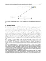
Figure 6.25 Schematic diagram of a p–n–p transistor.
and collector respectively, as shown in Figure 6.25,
and the base is made slightly negative and the collector
more negative relative to the emitter. The emitter-
base junction is therefore forward-biased and a strong
current of holes passes through the junction into the
n-layer which, because it is thin (10
2
mm), largely
reach the collector base junction without recombining
with electrons. The collector-base junction is reverse-
biased and the junction is no barrier to the passage of
holes; the current through the second junction is thus
controlled by the current through the first junction.
A small increase in voltage across the emitter-base
junction produces a large injection of holes into the
base and a large increase in current in the collector, to
give the amplifying action of the transistor.
Many varied semiconductor materials such as InSb
and GaAs have been developed apart from Si and Ge.
However, in all cases very high purity and crystal
perfection is necessary for efficient semiconducting
operations and to produce the material, zone-refining
techniques are used. Semiconductor integrated circuits
are extensively used in micro-electronic equipment
and these are produced by vapour deposition through
masks on to a single Si-slice, followed by diffusion of
the deposits into the base crystal.
Doped ceramic materials are used in the construc-
tion of thermistors, which are semiconductor devices
with a marked dependence of electrical resistivity upon
temperature. The change in resistance can be quite
significant at the critical temperature. Positive temper-
ature coefficient (PTC) thermistors are used as switch-
ing devices, operating when a control temperature is
reached during a heating process. PTC thermistors are
commonly based on barium titanate. Conversely, NTC
thermistors are based on oxide ceramics and can be
used to signal a desired temperature change during
cooling; the change in resistance is much more gradual
and does not have the step-characteristic of the PTC
types.
Doped zinc oxide does not exhibit the linear volt-
age/current relation that one expects from Ohm’s Law.
At low voltage, the resistivity is high and only a small
current flows. When the voltage increases there is a
sudden decrease in resistance, allowing a heavier cur-
rent to flow. This principle is adopted in the varistor,
a voltage-sensitive on/off switch. It is wired in parallel
with high-voltage equipment and can protect it from
transient voltage ‘spikes’ or overload.
6.7.3 Superconductivity
At low temperatures (<20 K) some metals have zero
electrical resistivity and become superconductors. This
superconductivity disappears if the temperature of
the metal is raised above a critical temperature T
c
,
if a sufficiently strong magnetic field is applied or
when a high current density flows. The critical field
strength H
c
, current density J
c
and temperature T
c
are
interdependent. Figure 6.26 shows the dependence of
H
c
on temperature for a number of metals; metals with
high T
c
and H
c
values, which include the transition
elements, are known as hard superconductors, those
with low values such as Al, Zn, Cd, Hg, white-Sn are
soft superconductors. The curves are roughly parabolic
and approximate to the relation H
c
D H
0
[1 T/T
c
2
]
where H
0
is the critical field at 0 K; H
0
is about
1.6 ð 10
5
A/m for Nb.
Superconductivity arises from conduction elec-
tron–electron attraction resulting from a distortion of
the lattice through which the electrons are travelling;
this is clearly a weak interaction since for most metals
it is destroyed by thermal activation at very low tem-
peratures. As the electron moves through the lattice
it attracts nearby positive ions thereby locally caus-
ing a slightly higher positive charge density. A nearby
electron may in turn be attracted by the net positive
charge, the magnitude of the attraction depending on
the electron density, ionic charge and lattice vibrational
frequencies such that under favourable conditions the
effect is slightly stronger than the electrostatic repul-
sion between electrons. The importance of the lattice
ions in superconductivity is supported by the obser-
vation that different isotopes of the same metal (e.g.
Sn and Hg) have different T
c
values proportional to
M
1/2
,whereM is the atomic mass of the isotope.
Since both the frequency of atomic vibrations and
the velocity of elastic waves also varies as M
1/2
,
the interaction between electrons and lattice vibrations
Figure 6.26 Variation of critical field H
c
as a function of
temperature for several pure metal superconductors.
186 Modern Physical Metallurgy and Materials Engineering
(i.e. electron–phonon interaction) must be at least one
cause of superconductivity.
The theory of superconductivity indicates that the
electron–electron attraction is strongest between elec-
trons in pairs, such that the resultant momentum of
each pair is exactly the same and the individual elec-
trons of each pair have opposite spin. With this partic-
ular form of ordering the total electron energy (i.e.
kinetic and interaction) is lowered and effectively
introduces a finite energy gap between this organized
state and the usual more excited state of motion. The
gap corresponds to a thin shell at the Fermi surface,
but does not produce an insulator or semiconductor,
because the application of an electric field causes the
whole Fermi distribution, together with gap, to drift
to an unsymmetrical position, so causing a current to
flow. This current remains even when the electric field
is removed, since the scattering which is necessary to
alter the displaced Fermi distribution is suppressed.
At 0 K all the electrons are in paired states but as
the temperature is raised, pairs are broken by thermal
activation giving rise to a number of normal electrons
in equilibrium with the superconducting pairs. With
increasing temperature the number of broken pairs
increases until at T
c
they are finally eliminated together
with the energy gap; the superconducting state then
reverts to the normal conducting state. The supercon-
ductivity transition is a second-order transformation
and a plot of C/T as a function of T
2
deviates from
the linear behaviour exhibited by normal conducting
metals, the electronic contribution being zero at 0 K.
The main theory of superconductivity, due to Bardeen,
Cooper and Schrieffer (BCS) attempts to relate T
c
to
the strength of the interaction potential, the density
of states at the Fermi surface and to the average fre-
quency of lattice vibration involved in the scattering,
and provides some explanation for the variation of T
c
with the e/a ratio for a wide range of alloys, as shown
in Figure 6.27. The main effect is attributable to the
Figure 6.27 The variation of T
c
with position in the
periodic table (from Mathias, 1959, p. 138; courtesy of
North-Holland Publishing Co.).
change in density of states with e/a ratio. Supercon-
ductivity is thus favoured in compounds of polyvalent
atoms with crystal structures having a high density of
states at the Fermi surface. Compounds with high T
c
values, such as Nb
3
Sn (18.1 K), Nb
3
Al (17.5 K), V
3
Si
(17.0 K), V
3
Ga (16.8 K), all crystallize with the ˇ-
tungsten structure and have an e/a ratio close to 4.7;
T
c
is very sensitive to the degree of order and to devi-
ation from the stoichiometric ratio, so values probably
correspond to the non-stoichiometric condition.
The magnetic behaviour of superconductivity is as
remarkable as the corresponding electrical behaviour,
as shown in Figure 6.28 by the Meissner effect for
an ideal (structurally perfect) superconductor. It is
observed for a specimen placed in a magnetic field
H < H
c
, which is then cooled down below T
c
,that
magnetic lines of force are pushed out. The specimen
is a perfect diamagnetic material with zero inductance
as well as zero resistance. Such a material is termed
an ideal type I superconductor. An ideal type II super-
conductor behaves similarly at low field strengths, with
H<H
cl
<H
c
, but then allows a gradual penetration
of the field returning to the normal state when pen-
etration is complete at H>H
c2
>H
c
. In detail, the
field actually penetrates to a small extent in type I
superconductors when it is below H
c
and in type II
superconductors when H is below H
cl
, and decays
away at a penetration depth ³100–10 nm.
The observation of the Meissner effect in type I
superconductors implies that the surface between the
normal and superconducting phases has an effective
positive energy. In the absence of this surface energy,
the specimen would break up into separate fine regions
of superconducting and normal material to reduce the
work done in the expulsion of the magnetic flux. A
negative surface energy exists between the normal
and superconducting phases in a type II superconduc-
tor and hence the superconductor exists naturally in
a state of finely-separated superconducting and nor-
mal regions. By adopting a ‘mixed state’ of normal
and superconducting regions the volume of interface is
maximized while at the same time keeping the volume
Figure 6.28 The Meissner effect; shown by the expulsion of
magnetic flux when the specimen becomes superconducting.
The physical properties of materials 187
of normal conduction as small as possible. The struc-
ture of the mixed state is believed to consist of lines
of normal phases parallel to the applied field through
which the field lines run, embedded in a supercon-
ducting matrix. The field falls off with distances from
the centre of each line over the characteristic distance
, and vortices or whirlpools of supercurrents flow
around each line; the flux line, together with its cur-
rent vortex, is called a fluxoid. At H
c1
, fluxoids appear
in the specimen and increase in number as the mag-
netic field is raised. At H
c2
, the fluxoids completely fill
the cross-section of the sample and type II supercon-
ductivity disappears. Type II superconductors are of
particular interest because of their high critical fields
which makes them potentially useful for the construc-
tion of high-field electromagnetics and solenoids. To
produce a magnetic field of ³10 T with a conven-
tional solenoid would cost more than ten times that of
a superconducting solenoid wound with Nb
3
Sn wire.
By embedding Nb wire in a bronze matrix it is pos-
sible to form channels of Nb
3
Sn by interdiffusion.
The conventional installation would require consid-
erable power, cooling water and space, whereas the
superconducting solenoid occupies little space, has no
steady-state power consumption and uses relatively
little liquid helium. It is necessary, however, for the
material to carry useful currents without resistance
in such high fields, which is not usually the case in
annealed homogeneous type II superconductors. For-
tunately, the critical current density is extremely sen-
sitive to microstructure and is markedly increased by
precipitation-hardening, cold work, radiation damage,
etc., because the lattice defects introduced pin the flux-
oids and tend to immobilize them. Figure 6.29 shows
the influence of metallurgical treatment on the critical
current density.
Figure 6.29 The effect of processing on the J
c
versus H
curve of an Nb–25% Zr alloy wire which produces a fine
precipitate and raises J
c
(from Rose, Shepard and Wulff,
1966; courtesy of John Wiley and Sons).
6.7.4 Oxide superconductors
In 1986 a new class of ‘warm’ superconductors, based
on mixed ceramic oxides, was discovered by J. G.
Bednorz and K. A. M
¨
uller. These lanthanum–copper
oxide superconductors had a T
c
around 35 K, well
above liquid hydrogen temperature. Since then, three
mixed oxide families have been developed with much
higher T
c
values, all around 100 K. Such materials
give rise to optimism for superconductor technology;
first, in the use of liquid nitrogen rather than liquid
hydrogen and second, in the prospect of producing a
room temperature superconductor.
The first oxide family was developed by mixing
and heating the three oxides Y
2
O
3
, BaO and CuO.
This gives rise to the mixed oxide YBa
2
Cu
3
O
7x
,
sometimes referred to as 1–2–3 compound or YBCO.
The structure is shown in Figure 6.30 and is basically
made by stacking three perovskite-type unit cells one
above the other; the top and bottom cells have barium
ions at the centre and copper ions at the corners, the
middle cell has yttrium at the centre. Oxygen ions sit
half-way along the cell edges but planes, other than
those containing barium, have some missing oxygen
ions (i.e. vacancies denoted by x in the oxide formula).
This structure therefore has planes of copper and
oxygen ions containing vacancies, and copper–oxygen
ion chains perpendicular to them. YBCO has a T
c
value of about 90 K which is virtually unchanged
when yttrium is replaced by other rare earth elements.
The second family of oxides are Bi–Ca–Sr–Cu–O
x
materials with the metal ions in the ratio of 2111,
2122 or 2223, respectively. The 2111 oxide has only
one copper–oxygen layer between the bismuth-oxygen
layers, the 2122 two and the 2223 three giving rise to
an increasing T
c
up to about 105 K. The third family
is based on Tl–Ca–Ba–Cu–O with a 2223 structure
having three copper–oxygen layers and a T
c
of about
125 K.
While these oxide superconductors have high T
c
values and high critical magnetic field (H
c
)-values,
they unfortunately have very low values of J
c
,the
critical current density. A high J
c
is required if they
are to be used for powerful superconducting magnets.
Electrical applications are therefore unlikely until the
J
c
value can be raised by several orders of magni-
tude comparable to those of conventional supercon-
ductors, i.e. 10
6
Acm
2
. The reason for the low J
c
is thought to be largely due to the grain boundaries
in polycrystalline materials, together with dislocations,
voids and impurity particles. Single crystals show J
c
values around 10
5
Acm
2
and textured materials, pro-
duced by melt growth techniques, about 10
4
Acm
2
,
but both processes have limited commercial applica-
tion. Electronic applications appear to be more promis-
ing since it is in the area of thin (1
µm) films that
high J
c
values have been obtained. By careful deposi-
tion control, epitaxial and single-crystal films having
J
c
× 10
6
Acm
2
with low magnetic field dependence
have been produced.
188 Modern Physical Metallurgy and Materials Engineering
Figure 6.30 Structure of 1–2–3 compound; the unit cell of the 90 K superconducting perovskite, YBa
2
Cu
3
O
7x
,where
x ¾ 0 (by courtesy of P. J. Hirst, Superconductivity Research Group, University of Birmingham, UK).
6.8 Magnetic properties
6.8.1 Magnetic susceptibility
When a metal is placed in a magnetic field of strength
H, the field induced in the metal is given by
B D H C 4I (6.17)
where I is the intensity of magnetization. The quantity
I is a characteristic property of the metal, and is related
to the susceptibility per unit volume of the metal which
is defined as
Ä D I/H (6.18)
The susceptibility is usually measured by a method
which depends upon the fact that when a metal
specimen is suspended in a non-uniform transverse
magnetic field, a force proportional to ÄV.H.dH/dx,
where V is the volume of the specimen and dH/dx
is the field gradient measured transversely to the lines
of force, is exerted upon it. This force is easily mea-
sured by attaching the specimen to a sensitive bal-
ance, and one type commonly used is that designed
by Sucksmith. In this balance the distortion of a
copper–beryllium ring, caused by the force on the
specimen, is measured by means of an optical or
electro-mechanical system. Those metals for which Ä is
negative, such as copper, silver, gold and bismuth, are
repelled by the field and are termed diamagnetic mate-
rials. Most metals, however, have positive Ä values
(i.e. they are attracted by the field) and are either para-
magnetic (when Ä is small) or ferromagnetic (when Ä
is very large). Only four pure metals–iron, cobalt and
nickel from the transition series, and gadolinium from
the rare earth series–are ferromagnetic Ä ³ 1000
at room temperature, but there are several ferromag-
netic alloys and some contain no metals which are
themselves ferromagnetic. The Heusler alloy, which
contains manganese, copper and aluminium, is one
example; ferromagnetism is due to the presence of one
of the transition metals.
The ability of a ferromagnetic metal to concen-
trate the lines of force of the applied field is of great
practical importance, and while all such materials can
be both magnetized and demagnetized, the ease with
which this can be achieved usually governs their appli-
cation in the various branches of engineering. Materi-
als may be generally classified either as magnetically
soft (temporary magnets) or as magnetically hard (per-
manent magnets), and the difference between the two
The physical properties of materials 189
Figure 6.31 B–H curves for (a) soft and (b) hard magnets.
types of magnet may be inferred from Figure 6.31.
Here, H is the magnetic field necessary to induce a
field of strength B inside the material. Upon removal
of the field H, a certain residual magnetism B
r
, known
as the remanence residual, is left in the specimen, and
afieldH
c
, called the coercive force, must be applied
in the opposite direction to remove it. A soft magnet
is one which is easy both to magnetize and to demag-
netize and, as shown in Figure 6.31a, a low value of
H is sufficient to induce a large field B in the metal,
while only a small field H
c
is required to remove it;
a hard magnet is a material that is magnetized and
demagnetized with difficulty (Figure 6.31b).
6.8.2 Diamagnetism and paramagnetism
Diagmagnetism is a universal property of the atom
since it arises from the motion of electrons in their
orbits around the nucleus. Electrons moving in this
way represent electrical circuits and it follows from
Lenz’s law that this motion is altered by an applied
field in such a manner as to set up a repulsive force.
The diamagnetic contribution from the valency elec-
trons is small, but from a closed shell it is proportional
to the number of electrons in it and to the square of the
radius of the ‘orbit’. In many metals this diamagnetic
effect is outweighed by a paramagnetic contribution,
the origin of which is to be found in the electron
spin. Each electron behaves like a small magnet and
in a magnetic field can take up one of two orienta-
tions, either along the field or in the other opposite
direction, depending on the direction of the electron
spin. Accordingly, the energy of the electron is either
decreased or increased and may be represented conve-
niently by the band theory. Thus, if we regard the band
of energy levels as split into two halves (Figure 6.32a),
each half associated with electrons of opposite spin, it
follows that in the presence of the field, some of the
electrons will transfer their allegiance from one band
to the other until the Fermi energy level is the same in
both. It is clear, therefore, that in this state there will be
a larger number of electrons which have their energy
lowered by the field than have their energy raised. This
condition defines paramagnetism, since there will be an
excess of unpaired spins which give rise to a resultant
magnetic moment.
It is evident that an insulator will not be paramag-
netic since the bands are full and the lowered half-band
cannot accommodate those electrons which wish to
‘spill over’ from the raised half-band. On the other
hand, it is not true, as one might expect, that conduc-
tors are always paramagnetic. This follows because
in some elements the natural diamagnetic contribution
outweighs the paramagnetic contribution; in copper,
for example, the newly filled d-shell gives rise to a
larger diamagnetic contribution.
6.8.3 Ferromagnetism
The theory of ferromagnetism is difficult and at present
not completely understood. Nevertheless, from the
electron theory of metals it is possible to build up
a band picture of ferromagnetic materials which goes
a long way to explain not only their ferromagnetic
properties but also the associated high resistivity and
electronic specific heat of these metals compared to
copper. In recent years considerable experimental work
has been done on the electronic behaviour of the tran-
sition elements, and this suggests that the electronic
structure of iron is somewhat different to that of cobalt
and nickel.
Ferromagnetism, like paramagnetism, has its ori-
gin in the electron spin. In ferromagnetic materials,
however, permanent magnetism is obtained and this
indicates that there is a tendency for electron spins to
remain aligned in one direction even when the field
has been removed. In terms of the band structure this
means that the half-band associated with one spin is
automatically lowered when the vacant levels at its
top are filled by electrons from the top of the other
Figure 6.32 Schematic representation of (a) paramagnetic
nickel and (b) ferromagnetic nickel (after Raynor, 1958; by
courtesy of Inst. of Materials).
190 Modern Physical Metallurgy and Materials Engineering
(Figure 6.32b); the change in potential energy asso-
ciated with this transfer is known as the exchange
energy. Thus, while it is energetically favourable for
a condition in which all the spins are in the same
direction, an opposing factor is the Pauli exclusion
principle, because if the spins are aligned in a single
direction many of the electrons will have to go into
higher quantum states with a resultant increase in
kinetic energy. In consequence, the conditions for
ferro-magnetism are stringent, and only electrons from
partially filled d or f levels can take part. This con-
dition arises because only these levels have (1) vacant
levels available for occupation, and (2) a high density
of states which is necessary if the increase in kinetic
energy accompanying the alignment of spins is to be
smaller than the decrease in exchange energy. Both of
these conditions are fulfilled in the transition and rare-
earth metals, but of all the metals in the long periods
only the elements iron, cobalt and nickel are ferromag-
netic at room temperature, gadolinium just above RT
T
c
³ 16
°
C and the majority are in fact strongly para-
magnetic. This observation has led to the conclusion
that the exchange interactions are most favourable, at
least for the iron group of metals, when the ratio of
the atomic radius to the radius of the unfilled shell, i.e.
the d-shell, is somewhat greater than 3 (see Table 6.1).
As a result of this condition it is hardly surprising that
there are a relatively large number of ferromagnetic
alloys and compounds, even though the base elements
themselves are not ferromagnetic.
In ferromagnetic metals the strong interaction results
in the electron spins being spontaneously aligned, even
in the absence of an applied field. However, a specimen
of iron can exist in an unmagnetized condition because
such an alignment is limited to small regions, or
domains, which statistically oppose each other. These
domains are distinct from the grains of a polycrys-
talline metal and in general there are many domains
in a single grain, as shown in Figure 6.33. Under
the application of a magnetic field the favourably-
oriented domains grow at the expense of the others
by the migration of the domain boundaries until the
whole specimen appears fully magnetized. At high
Table 6.1 Radii (nm) of electronic orbits of atoms of tran-
sition metals of first long period (after Slater, Quantum
Theory of Matter)
Element 3d 4s Atomic radius
in metal (nm)
Sc 0.061 0.180 0.160
Ti 0.055 0.166 0.147
V 0.049 0.152 0.136
Cr 0.045 0.141 0.128
Mn 0.042 0.131 0.128
Fe 0.039 0.122 0.128
Co 0.036 0.114 0.125
Ni 0.034 0.107 0.125
Cu 0.032 0.103 0.128
Figure 6.33 Simple domain structure in a ferromagnetic
material. The arrows indicate the direction of magnetization
in the domains.
field strengths it is also possible for unfavourably-
oriented domains to ‘snap-over’ into more favourable
orientations quite suddenly, and this process, which
can often be heard using sensitive equipment, is known
as the Barkhausen effect.
The state in which all the electron spins are in com-
plete alignment is possible only at low temperatures.
As the temperature is raised the saturation magnetiza-
tion is reduced, falling slowly at first and then increas-
ingly rapidly, until a critical temperature, known as
the Curie temperature, is reached. Above this temper-
ature, T
c
, the specimen is no longer ferromagnetic, but
becomes paramagnetic, and for the metals iron, cobalt,
and nickel this transition occurs at 780
°
C, 1075
°
C
and 365
°
C. respectively. Such a cooperative process
may be readily understood from thermodynamic rea-
soning, since the additional entropy associated with
the disorder of the electron spins makes the disordered
(paramagnetic) state thermodynamically more stable at
high temperatures. This behaviour is similar to that
shown by materials which undergo the order–disorder
transformation and, as a consequence, ferromagnetic
metals exhibit a specific heat peak of the form previ-
ously shown (see Figure 6.4b).
A ferromagnetic crystal in its natural state has a
domain structure. From Figure 6.33 it is clear that
by dividing itself into domains the crystal is able to
eliminate those magnetic poles which would otherwise
occur at the surface. The width of the domain boundary
or Bloch wall is not necessarily small, however, and
in most materials is of the order of 100 atoms in
thickness. By having a wide boundary the electron
spins in neighbouring atoms are more nearly parallel,
which is a condition required to minimize the exchange
energy. On the other hand, within any one domain
the direction of magnetization is parallel to a direction
of easy magnetization (i.e. h100i in iron, h111i in
nickel and h001i in cobalt) and as one passes across a
boundary the direction of magnetization rotates away
from one direction of easy magnetization to another.
To minimize this magnetically-disturbed region the
crystal will try to adopt a boundary which is as thin as
possible. Consequently, the boundary width adopted is
The physical properties of materials 191
one of compromise between the two opposing effects,
and the material may be considered to possess a
magnetic interfacial or surface energy.
6.8.4 Magnetic alloys
The work done in moving a domain boundary depends
on the energy of the boundary, which in turn depends
on the magnetic anisotropy. The ease of magnetiza-
tion also depends on the state of internal strain in the
material and the presence of impurities. Both these
latter factors affect the magnetic ‘hardness’ through
the phenomenon of magnetostriction, i.e. the lattice
constants are slightly altered by the magnetization so
that a directive influence is put upon the orientation of
magnetization of the domains. Materials with inter-
nal stresses are hard to magnetize or demagnetize,
while materials free from stresses are magnetically
soft. Hence, since internal stresses are also responsible
for mechanical hardness, the principle which governs
the design of magnetic alloys is to make permanent
magnetic materials as mechanically hard and soft mag-
nets as mechanically soft as possible.
Magnetically soft materials are used for trans-
former laminations and armature stampings where a
high permeability and a low hysteresis are desirable:
iron–silicon or iron–nickel alloys are commonly used
for this purpose. In the development of magnetically
soft materials it is found that those elements which
form interstitial solid solutions with iron are those
which broaden the hysteresis loop most markedly. For
this reason, it is common to remove such impurities
from transformer iron by vacuum melting or hydrogen
annealing. However, such processes are expensive and,
consequently, alloys are frequently used as ‘soft’ mag-
nets, particularly iron–silicon and iron–nickel alloys
(because silicon and nickel both reduce the amount
of carbon in solution). The role of Si is to form a
-loop and hence remove transformation strains and
also improve orientation control. In the production of
iron–silicon alloys the factors which are controlled
include the grain size, the orientation difference from
one grain to the next, and the presence of non-magnetic
inclusions, since all are major sources of coercive
force. The coercive force increases with decreasing
grain size because the domain pattern in the neigh-
bourhood of a grain boundary is complicated owing to
the orientation difference between two adjacent grains.
Complex domain patterns can also arise at the free
surface of the metal unless these are parallel to a direc-
tion of easy magnetization. Accordingly, to minimize
the coercive force, rolling and annealing schedules are
adopted to produce a preferred oriented material with
a strong ‘cube-texture’, i.e. one with two h100i direc-
tions in the plane of the sheet (see Chapter 7). This
procedure is extremely important, since transformer
material is used in the form of thin sheets to mini-
mize eddy-current losses. Fe–Si–B in the amorphous
state is finding increasing application in transformers.
The iron–nickel series, Permalloys, present many
interesting alloys and are used chiefly in communica-
tion engineering where a high permeability is a neces-
sary condition. The alloys in the range 40–55% nickel
are characterized by a high permeability and at low
field strengths this may be as high as 15000 compared
with 500 for annealed iron. The 50% alloy, Hyper-
nik, may have a permeability which reaches a value
of 70000, but the highest initial and maximum perme-
ability occurs in the composition range of the FeNi
3
superlattice, provided the ordering phenomenon is sup-
pressed. An interesting development in this field is in
the heat treatment of the alloys while in a strong mag-
netic field. By such a treatment the permeability of
Permalloy 65 has been increased to about 260 000.
This effect is thought to be due to the fact that dur-
ing alignment of the domains, plastic deformation is
possible and magnetostrictive strains may be relieved.
Magnetically hard materials are used for applica-
tions where a ‘permanent magnetic field is required,
but where electromagnets cannot be used, such as
in electric clocks, meters, etc. Materials commonly
used for this purpose include Alnico (Al–Ni–Co)
alloys, Cunico (Cu–Ni–Co) alloys, ferrites (barium
and strontium), samarium–cobalt alloys (SmCo
5
and
Sm
2
Co, Fe, Cu, Zr
17
)andNeomax Nd
2
Fe
14
B.The
Alnico alloys have high remanence but poor coerciv-
ities, the ferrites have rather low remanence but good
coercivities together with very cheap raw material
costs. The rare-earth magnets have a high performance
but are rather costly although the Nd-based alloys are
cheaper than the Sm-based ones.
In the development of magnetically hard materials,
the principle is to obtain, by alloying and heat treat-
ment, a matrix containing finely divided particles of
a second phase. These fine precipitates, usually dif-
fering in lattice parameter from the matrix, set up
coherency strains in the lattice which affect the domain
boundary movement. Alloys of copper–nickel–iron,
copper–nickel–cobalt and aluminium–nickel–cobalt
are of this type. An important advance in this field
is to make the particle size of the alloy so small, i.e.
less than a hundred nanometres diameter, that each
grain contains only a single domain. Then magneti-
zation can occur only by the rotation of the direc-
tion of magnetization en bloc. Alnico alloys con-
taining 6–12% Al, 14–25% Ni, 0–35% Co, 0–8%
Ti, 0–6% Cu in 40–70% Fe depend on this fea-
ture and are the most commercially important perma-
nent magnet materials. They are precipitation-hardened
alloys and are heat-treated to produce rod-like pre-
cipitates (30 nm ð 100 nm) lying along h100i in the
bcc matrix. During magnetic annealing the rods form
along the h100i axis nearest to the direction of the
field, when the remanence and coercivity are markedly
increased, Sm
2
Co, Fe, Cu, Zr
17
alloys also rely on
the pinning of magnetic domains by fine precipitates.
Clear correlation exists between mechanical hardness
and intrinsic coercivity. SmCo
5
magnets depend on
the very high magnetocrystalline anisotropy of this
192 Modern Physical Metallurgy and Materials Engineering
compound and the individual grains are single-domain
particles. The big advantage of these magnets over the
Alnico alloys is their much higher coercivities.
The Heusler alloys, copper–manganese–aluminium,
are of particular interest because they are made up
from non-ferromagnetic metals and yet exhibit ferro-
magnetic properties. The magnetism in this group of
alloys is associated with the compound Cu
2
MnAl, evi-
dently because of the presence of manganese atoms.
The compound has the Fe
3
Al-type superlattice when
quenched from 800
°
C, and in this state is ferromag-
netic, but when the alloy is slowly cooled it has
a -brass structure and is non-magnetic, presumably
because the correct exchange forces arise from the lat-
tice rearrangement on ordering. A similar behaviour is
found in both the copper–manganese–gallium and the
copper–manganese–indium systems.
The order–disorder phenomenon is also of magnetic
importance in many other systems. As discussed pre-
viously, when ordering is accompanied by a structural
change, i.e. cubic to tetragonal, coherency strains are
set up which often lead to magnetic hardness. In FePt,
for example, extremely high coercive forces are pro-
duced by rapid cooling. However, because the change
in mechanical properties accompanying the transfor-
mation is found to be small, it has been suggested that
the hard magnetic properties in this alloy are due to the
small particle-size effect, which arises from the finely
laminated state of the structure.
6.8.5 Anti-ferromagnetism and
ferrimagnetism
Apart from the more usual dia-, para- and
ferromagnetic materials, there are certain substances
which are termed anti-ferromagnetic; in these, the
net moments of neighbouring atoms are aligned in
opposite directions, i.e. anti-parallel. Many oxides
and chlorides of the transition metals are examples
including both chromium and ˛-manganese, and
also manganese–copper alloys. Some of the relevant
features of anti-ferromagnetism are similar in many
respects to ferromagnetism, and are summarized as
follows:
1. In general, the magnetization directions are aligned
parallel or anti-parallel to crystallographic axes, e.g.
in MnI and CoO the moment of the Mn
2C
and Co
2C
ions are aligned along a cube edge of the unit cell.
The common directions are termed directions of
anti-ferromagnetism.
2. The degree of long-range anti-ferromagnetic order-
ing progressively decreases with increasing temper-
ature and becomes zero at a critical temperature,
T
n
, known as the N
´
eel temperature; this is the anti-
ferromagnetic equivalent of the Curie temperature.
3. An anti-ferromagnetic domain is a region in which
there is only one common direction of anti-
ferromagnetism; this is probably affected by lattice
defects and strain.
The most characteristic property of an anti-
ferromagnetic material is that its susceptibility shows
a maximum as a function of temperature, as shown in
Figure 6.34a. As the temperature is raised from 0 K the
interaction which leads to anti-parallel spin alignment
becomes less effective until at T
n
the spins are free.
Similar characteristic features are shown in the resis-
tivity curves due to scattering as a result of spin dis-
order. However, the application of neutron diffraction
techniques provides a more direct method of study-
ing anti-ferromagnetic structures, as well as giving
the magnetic moments associated with the ions of the
metal. There is a magnetic scattering of neutrons in
the case of certain magnetic atoms, and owing to the
different scattering amplitude of the parallel and anti-
parallel atoms, the possibility arises of the existence
of superlattice lines in the anti-ferromagnetic state.
In manganese oxide MnO, for example, the param-
eter of the magnetic unit cell is 0.885 nm, whereas the
chemical unit cell (NaCl structure) is half this value,
0.443 nm. This atomic arrangement is analogous to the
Figure 6.34 (a) Variation of magnetic susceptibility with temperature for an anti-ferromagnetic material, (b) neutron
diffraction pattern from the anti-ferromagnetic powder MnO above and below the critical temperature for ordering (after Shull
and Smart, 1949).
The physical properties of materials 193
structure of an ordered alloy and the existence of mag-
netic superlattice lines below the N
´
eel point (122 K)
has been observed, as shown in Figure 6.34b.
Some magnetic materials have properties which
are intermediate between those of anti-ferromagnetic
and ferromagnetic. This arises if the moments in one
direction are unequal in magnitude to those in the
other, as, for example, in magnetite, Fe
3
O
4
,wherethe
ferrous and ferric ions of the FeO.Fe
2
O
3
compound
occupy their own particular sites. N
´
eel has called this
state ferrimagnetism and the corresponding materials
are termed ferrites. Such materials are of importance
in the field of electrical engineering because they are
ferromagnetic without being appreciably conducting;
eddy current troubles in transformers are, therefore,
not so great. Strontium ferrite is extensively used in
applications such as electric motors, because of these
properties and low material costs.
6.9 Dielectric materials
6.9.1 Polarization
Dielectric materials, usually those which are covalent
or ionic, possess a large energy gap between the
valence band and the conduction band. These materials
exhibit high electrical resistivity and have important
applications as insulators, which prevent the transfer of
electrical charge, and capacitors which store electrical
charge. Dielectric materials also exhibit piezoelectric
and ferroelectric properties.
Application of an electric field to a material induces
the formation of dipoles (i.e. atoms or groups of
atoms with an unbalanced charge or moment) which
become aligned with the direction of the applied field.
The material is then polarized. This state can arise
from several possible mechanisms–electronic, ionic
or molecular, as shown in Figure 6.35a-c. With elec-
tronic polarization, the electron clouds of an atom are
displaced with respect to the positively-charged ion
core setting up an electric dipole with moment
e
.For
ionic solids in an electric field, the bonds between the
ions are elastically deformed and the anion–cation dis-
tances become closer or further apart, depending on the
direction of the field. These induced dipoles produce
polarization and may lead to dimensional changes.
Molecular polarization occurs in molecular materials,
some of which contain natural dipoles. Such materials
are described as polar and for these the influence of an
applied field will change the polarization by displacing
the atoms and thus changing the dipole moment (i.e.
atomic polarizability) or by causing the molecule as a
whole to rotate to line up with the imposed field (i.e.
orientation polarizability). When the field is removed
these dipoles may remain aligned, leading to perma-
nent polarization. Permanent dipoles exist in asymmet-
rical molecules such as H
2
O, organic polymers with
asymmetric structure and ceramic crystals without a
centre of symmetry.
6.9.2 Capacitors and insulators
In a capacitor the charge is stored in a dielectric mate-
rial which is easily polarized and has a high electrical
resistivity ¾10
11
VA
1
m to prevent the charge flow-
ing between conductor plates. The ability of the mate-
rial to polarize is expressed by the permittivity ε and
the relative permittivity or dielectric constant Ä is the
ratio of the permittivity of the material and the permit-
tivity of a vacuum ε
0
. While a high Ä is important for a
capacitor, a high dielectric strength or breakdown volt-
age is also essential. The dielectric constant Ä values
for vacuum, water, polyethylene, Pyrex glass, alumina
and barium titanate are 1, 78.3, 2.3, 4, 6.5 and 3000,
respectively.
Structure is an important feature of dielectric
behaviour. Glassy polymers and crystalline materials
have a lower Ä than their amorphous counterparts.
Polymers with asymmetric chains have a high Ä
because of the strength of the associated molecular
dipole; thus polyvinyl chloride (PVC) and polystyrene
(PS) have larger Ä’s than polyethylene (PE). BaTiO
3
has an extremely high Ä value because of its
asymmetrical structure. Frequency response is also
important in dielectric application, and depends on
the mechanism of polarization. Materials which rely
on electronic and ionic dipoles respond rapidly
to frequencies of 10
13
–10
16
Hz but molecular
polarization solids, which require groups of atoms
to rearrange, respond less rapidly. Frequency is also
important in governing dielectric loss due to heat and
Figure 6.35 Application of field to produce polarization by (a) electronic, (b) ionic and (c) molecular mechanisms.
194 Modern Physical Metallurgy and Materials Engineering
usually increases when one of the contributions to
polarization is prevented. This behaviour is common in
microwave heating of polymer adhesives; preferential
heating in the adhesive due to dielectric losses starts
the thermosetting reaction. For moderate increases,
raising the voltage and temperature increases the
polarizability and leads to a higher dielectric constant.
Nowadays, capacitor dielectrics combine materials
with different temperature dependence to yield a final
product with a small linear temperature variation.
These materials are usually titanates of Ba, Ca, Mg,
Sr and rare-earth metals.
For an insulator, the material must possess a high
electrical resistivity, a high dielectric strength to pre-
vent breakdown of the insulator at high voltages, a
low dielectric loss to prevent heating and small dielec-
tric constant to hinder polarization and hence charge
storage. Materials increasingly used are alumina, alu-
minium nitride, glass-ceramics, steatite porcelain and
glasses.
6.9.3 Piezoelectric materials
When stress is applied to certain materials an elec-
tric polarization is produced proportional to the stress
applied. This is the well-known piezoelectric effect.
Conversely, dilatation occurs on application of an
electric field. Common materials displaying this prop-
erty are quartz, BaTiO
3
, Pb(Ti, Zr)O
3
or PZT and
Na or LiNbO
3
. For quartz, the piezoelectric con-
stant d relating strain ε to field strength Fε D
d ð F is 2.3 ð 10
12
mV
1
, whereas for PZT it
is 250 ð10
12
mV
1
. The piezoelectric effect is
used in transducers which convert sound waves to
electric fields, or vice versa. Applications range
from microphones, where a few millivolts are gen-
erated, to military devices creating several kilo-
volts and from small sub-nanometre displacements in
piezoelectrically-deformed mirrors to large deforma-
tions in power transducers.
6.9.4 Pyroelectric and ferroelectric materials
Some materials, associated with low crystal symmetry,
are observed to acquire an electric charge when
heated; this is known as pyroelectricity. Because
of the low symmetry, the centre of gravity of the
positive and negative charges in the unit cell are
separated producing a permanent dipole moment.
Moreover, alignment of individual dipoles leads to
an overall dipole moment which is non-zero for the
crystal. Pyroelectric materials are used as detectors
of electromagnetic radiation in a wide band from
ultraviolet to microwave, in radiometers and in
thermometers sensitive to changes of temperature as
small as 6 ð10
6
°
C. Pyroelectric TV camera tubes
have also been developed for long-wavelength infrared
imaging and are useful in providing visibility through
smoke. Typical materials are strontium barium niobate
and PZT with Pb
2
FeNbO
6
additions to broaden the
temperature range of operation.
Ferroelectric materials are those which retain a
net polarization when the field is removed and is
explained in terms of the residual alignment of per-
manent dipoles. Not all materials that have perma-
nent dipoles exhibit ferroelectric behaviour because
these dipoles become randomly-arranged as the field
is removed so that no net polarization remains. Ferro-
electrics are related to the pyroelectrics; for the former
materials the direction of spontaneous polarization can
be reversed by an electric field (Figure 6.36) whereas
for the latter this is not possible. This effect can be
demonstrated by a polarization versus field hysteresis
loop similar in form and explanation to the B–H mag-
netic hysteresis loop (see Figure 6.31). With increasing
positive field all the dipoles align to produce a satura-
tion polarization. As the field is removed a remanent
polarization P
r
remains due to a coupled interaction
between dipoles. The material is permanently polarized
and a coercive field E
c
has to be applied to randomize
the dipoles and remove the polarization.
Like ferromagnetism, ferroelectricity depends on
temperature and disappears above an equivalent Curie
temperature. For BaTiO
3
, ferroelectricity is lost at
120
°
C when the material changes crystal structure. By
analogy with magnetism there is also a ferroelectric
analogue of anti-ferromagnetism and ferrimagnetism.
NaNbO
3
, for example, has a T
c
, of 640
°
C and anti-
parallel electric dipoles of unequal moments charac-
teristic of a ferrielectric material.
Figure 6.36 Hysteresis loop for ferroelectric materials,
showing the influence of electric field E on polarization P.
The physical properties of materials 195
6.10 Optical properties
6.10.1 Reflection, absorption and
transmission effects
The optical properties of a material are related to the
interaction of the material with electromagnetic radi-
ation, particularly visible light. The electromagnetic
spectrum is shown in Figure 5.1 from which it can be
seen that the wavelength varies from 10
4
m for radio
waves down to 10
14
mfor-rays and the correspond-
ing photon energies vary from 10
10
eV to 10
8
eV.
Photons incident on a material may be reflected,
absorbed or transmitted. Whether a photon is absorbed
or transmitted by a material depends on the energy gap
between the valency and conduction bands and the
energy of the photon. The band structure for metals
has no gap and so photons of almost any energy are
absorbed by exciting electrons from the valency band
into a higher energy level in the conduction band.
Metals are thus opaque to all electromagnetic radiation
from radio waves, through the infrared, the visible to
the ultraviolet, but are transparent to high-energy X-
rays and -rays. Much of the absorbed radiation is
reemitted as radiation of the same wavelength (i.e.
reflected). Metals are both opaque and reflective and
it is the wavelength distribution of the reflected light,
which we see, that determines the colour of the metal.
Thus copper and gold reflect only a certain range of
wavelengths and absorb the remaining photons, i.e.
copper reflects the longer-wavelength red light and
absorbs the shorter-wavelength blue. Aluminium and
silver are highly reflective over the complete range of
the visible spectrum and appear silvery.
Because of the gaps in their band structure non-
metals may be transparent. Thus if the photons have
insufficient energy to excite electrons in the mate-
rial to a higher energy level, they may be transmitted
rather than absorbed and the material is transparent.
In high-purity ceramics and polymers, the energy gap
is large and these materials are transparent to visible
light. In semiconductors, electrons can be excited into
acceptor levels or out of donor levels and phonons hav-
ing sufficient energy to produce these transitions will
be absorbed. Semiconductors are therefore opaque to
short wavelengths and transparent to long.
1
The band
structure is influenced by crystallinity and hence mate-
rials such as glasses and polymers may be transparent
in the amorphous state but opaque when crystalline.
High-purity non-metallics such as glasses, diamond
or sapphire Al
2
O
3
are colourless but are changed by
impurities. For example, small additions of Cr
3C
ions
Cr
2
O
3
to Al
2
O
3
produces a ruby colour by introduc-
ing impurity levels within the band-gap of sapphire
which give rise to absorption of specific wavelengths in
1
Figure 5.37b shows a dislocation source in the interior of a
silicon crystal observed using infrared light.
the visible spectrum. Colouring of glasses and ceram-
ics is produced by addition of transition metal impu-
rities which have unfilled d-shells. The photons easily
interact with these ions and are absorbed; Cr
3C
gives
green, Mn
2C
yellow and Co
2C
blue-violet colouring.
In photochromic sunglasses the energy of light
quanta is used to produce changes in the ionic structure
of the glass. The glass contains silver Ag
C
ions as a
dopant which are trapped in the disordered glass net-
work of silicon and oxygen ions: these are excited by
high-energy quanta (photons) and change to metallic
silver, causing the glass to darken (i.e. light energy is
absorbed). With a reduction in light intensity, the silver
atoms re-ionize. These processes take a small period of
time relying on absorption and non-absorption of light.
6.10.2 Optical fibres
Modern communication systems make use of the abil-
ity of optical fibres to transmit light signals over large
distances. Optical guidance by a fibre is produced (see
Figure 6.37) if a core fibre of refractive index n
1
is
surrounded by a cladding of slightly lower index n
2
such that total internal reflection occurs confining the
rays to the core; typically the core is about 100
µm
and n
1
n
2
³ 10
2
. With such a simple optical fibre,
interference occurs between different modes leading
to a smearing of the signals. Later designs use a
core in which the refractive index is graded, parabol-
ically, between the core axis and the interface with
the cladding. This design enables modulated signals to
maintain their coherency. In vitreous silica, the refrac-
tive index can be modified by additions of dopants such
as P
2
O
5
,GeO
2
which raise it and B
2
O
5
and F which
lower it. Cables are sheathed to give strength and envi-
ronmental protection; PE and PVC are commonly used
for limited fire-hazard conditions.
6.10.3 Lasers
A laser (Light Amplification by Stimulated Emission
of Radiation) is a powerful source of coherent light
(i.e. monochromatic and all in phase). The original
laser material, still used, is a single crystal rod of
ruby, i.e. Al
2
O
3
containing dopant Cr
3C
ions in solid
solution. Nowadays, lasers can be solid, liquid or
gaseous materials and ceramics, glasses and semicon-
ductors. In all cases, electrons of the laser material
are excited into a higher energy state by some suitable
stimulus (see Figure 6.38). In a device this is produced
by the photons from a flash tube, to give an intense
Figure 6.37 Optical guidance in a multimode fibre.