Heat Transfer Theoretical Analysis Experimental Investigations and Industrial Systems part 7 pptx
Bạn đang xem bản rút gọn của tài liệu. Xem và tải ngay bản đầy đủ của tài liệu tại đây (4.45 MB, 40 trang )
Heat Transfer - Theoretical Analysis, Experimental Investigations and Industrial Systems
230
Just as the case of smooth chip, the bubbles generate and departure continuously from the
heating surface caused by buoyancy forces in normal gravity before the release of the drop
capsule (Fig. 14a). However, the bubble number are much larger than that for the smooth
chip, indicating that the micro-pin-finned surface can provide larger number of nucleation
sites for enhancing boiling heat transfer performance. At about 0.12 s after entering the
microgravity condition, the vapour bubbles begin to coalesce with each other to form
several large bubbles attaching on the chip surface (Fig. 14b). Some small bubbles are in the
departure state when entering the microgravity condition, so we can still see them departing
from the heater surface at this time. With increasing time, the bubbles coalesce to form a
large spherical bubble (Fig. 14c). However, the large bubble covering on the heater surface
does not cause obvious increase of wall temperature (Fig. 15).
Fig. 16. Bulk liquid supply and micro-convection caused by capillary force (Wei et al., 2009).
The capillary force generated by the interface between the large bubble and the liquid of the
micro-layer beneath the bubble drives plenty of fresh liquid to contact with the superheated
wall for vaporization through the regular interconnected structures formed by the micro-
pin-fins, as well as improves the micro-convection heat transfer by the motion of liquid
around the micro-pin-fins, as shown schematically in Fig. 16. The sufficient supply of bulk
liquid to the heater surface guarantees the continuous growth of the large bubble. Therefore,
contrary to boiling on chip S, there is no deterioration of boiling heat transfer performance
for the micro-pin-finned surface in microgravity, and the heater surface temperature can
keep almost constant in both gravity and microgravity conditions.
In summary, the micro-pin-fined surface structure can provide large capillary force and
small flow resistance, driving a plenty of bulk liquid to access the heater surface for
evaporation in high heat flux region, which results in large boiling heat transfer
enhancement. Since the capillary force is no relevant to the gravity level, the micro-pin-fined
surface appears to be one promising enhanced surface for efficient electronic components
cooling schemes not only in normal gravity but also in microgravity conditions, which is
very helpful to reduce the cooling system weight in space and in planetary neighbors.
Nucleate Pool Boiling in Microgravity
231
5. Future researches on boiling in microgravity in china
A new project DEPA-SJ10 has been planned to be flown aboard the Chinese recoverable
satellite SJ-10 in the near future (Wan & Zhao, 2008). In the project, boiling at a single
artifical cavity will be used as a model for studying subsystems in nucleate pool boiling of
pure substances. Transient processes of bubble formation, growth and detachment will be
observed, while the temperature distribution near the active nucleation site will be
measured at subcooling and saturated conditions. The main aim is to describe bubble
behavior and convection around the growing vapor bubble in microgravity, to understand
small scale heat transfer mechanisms, and to reveal the physical phenomena governing
nucleate boiling.
Numerical simulation on single bubble boiling has also been proposed, in which the single
bubble boiling is set as a physical model for studying the thermo-dynamical behaviors of
bubbles, the heat transfer and the corresponding gravity effect in the phenomenon of
nucleate pool boiling (Zhao et al., 2010). According to some preliminary results, it was
indicated that the growing bubble diameter is approximately
proportional to the 0.4-th
power of the growing time. The detach diameter of bubble is proportional to the -1/3-th
power of the gravity, while the growing period to the -4/5-th power of the gravity. The heat
flux is
approximately proportional to the 1.5-th power of wall superheat with a fixed
number density of active nucleation sites in all the studied gravity levels. The heat transfer
through the micro-wedge region has a very important contribution to the whole
performance of boiling.
Further experimental investigation on the performance of micro-pin-finned surface has also
planned to be conducted in the drop tower Beijing, which aims to study the behaviour at
very high heat flux around the critical heat flux phenomenon, as well as to determine the
optimal structure of the micro-pin-fins.
These projects will be helpful for the improvement of understanding of such phenomena
themselves, as well as for the development of space systems involving boiling phenomenon.
6. Conclusion
Nucleate pool boiling is a daily phenomenon transferring effectively high heat flux. It is,
however, a very complex and illusive process. Among many sub-processes in boiling
phenomenon, gravity can be involved and play much important roles, even enshroud the
real mechanism underlying the phenomenon. Microgravity experiments offer a unique
opportunity to study the complex interactions without external forces, such as buoyancy,
which can affect the bubble dynamics and the related heat transfer. Furthermore, they can
also provide a means to study the actual influence of gravity on the boiling. On the other
hand, since many potential applications exist in space and in planetary neighbors due to its
high efficiency in heat transfer, pool boiling in microgravity has become an increasing
significant subject for investigation.
In the past decade, two research projects on nucleate pool boiling in microgravity have been
conducted aboard the Chinese recoverable satellites. Ground-based experiments both in
normal gravity and in short-term microgravity in the drop tower Beijing and numerical
simulations have also been performed. The major findings are summarized in the present
chapter.
Steady boiling of R113 on thin platinum wires was studied with a temperature-controlled
heating method, while quasi-steady boiling of FC-72 on a plane plate was investigated with
Heat Transfer - Theoretical Analysis, Experimental Investigations and Industrial Systems
232
an exponentially increasing heating voltage. It was found that the bubble dynamics in
microgravity has a distinct difference from that in normal gravity, and that the heat transfer
characteristic is depended upon the bubble dynamics. Lateral motions of bubbles on the
heaters were observed before their departure in microgravity. The surface oscillation of the
merged bubbles due to lateral coalescence between adjacent bubbles drove it to detach from
the heaters. Considering the influence of the Marangoni effects, the different characteristics
of bubble behaviors in microgravity have been explained. A new bubble departure model
has also been proposed, which can predict the whole observation both in microgravity and
in normal gravity.
Slight enhancement of heat transfer on wires is observed in microgravity, while diminution
is evident for high heat flux in the plate case. These different characteristics may be caused
by the difference of liquid supply underneath the growing bubbles in the above two
different cases. It is then suggested that a high performance of heat transfer will be obtained
in nucleate pool boiling in microgravity if effective supply of liquid is provided to the
bottom of growing bubbles. A series of experiments of pool boiling on a micro-pin-finned
surface have been carried out utilizing the drop tower Beijing. Although bubbles cannot
detach in microgravity but stay on the top of the micro-pin-fins, the fresh liquid may still
access to the heater surface through interconnect tunnels formed between micro-pin-fins
due to the capillary forces, which is independent of the gravity level. Therefore, no
deterioration of heat transfer in microgravity is observed even at much high heat flux close
to CHF observed in normal gravity.
The value of CHF on wires in microgravity is lower than that in normal gravity, but it can
still be predicted well by the correlation of Lienhard & Dhir (1973), although the
dimensionless radius in the present case is far beyond its initial application range. The
scaling of CHF with gravity is thus much different from the traditional viewpoint, and a
possible mechanism is suggested based on the experimental observations.
7. Acknowledgement
The studies presented here were supported financially by the National Natural Science
Foundation of China (10972225, 50806057, 10432060), the Chinese Academy of Sciences
(KJCX2-SW-L05, KACX2-SW-02-03), the Chinese National Space Agency, and the support
from the Key Laboratory of Microgravity/CAS for experiments utilizing the drop tower
Beijing. The author really appreciates Prof. W. R. Hu, Mr. S. X. Wan, Mr. M. G. Wei, and all
research fellows who have contributed to the success of these studies. The author also
wishes to acknowledge the fruitful discussion and collaboration with Prof. H. Ohta (Kyushu
University, Japan), Prof. J. J. Wei (Xi’an Jiaotong University, China).
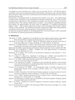
8. References
Di Marco, P., 2003. Review of reduced gravity boiling heat transfer: European research. J.
Jpn. Soc. Microgravity Appl., 20(4), 252–263.
Di Marco, P., Grassi, W., 1999. About the scaling of critical heat flux with gravity
acceleration in pool boiling. In: Proc. XVII UIT Nat. Heat Transfer Conf., Ferrara,
pp.139-149.
Di Marco, P., Grassi, W., 2009. Effect of force fields on pool boiling flow patterns in normal
and reduced gravity. Heat Mass Transfer, 45: 959-966.
Nucleate Pool Boiling in Microgravity
233
Johnson, H.A., 1971. Transient boiling heat transfer to water. Int. J. Heat Mass Transfer, 14,
67–82.
Kim, J., 2003. Review of reduced gravity boiling heat transfer: US research. J. Jpn. Soc.
Microgravity Appl., 20(4), 264–271.
Kim, J., Benton, J., Wisniewski, D., 2002. Pool boiling heat transfer on small heaters: effect of
gravity and subcooling. Int. J. Heat and Mass Transfer, 45: 3919-3932.
Lee, H.S., Merte, H., Jr., Chiaramonte, F., 1997. Pool boiling curve in microgravity. J.
Thermophy. Heat Transfer, 11(2), 216–222.
Lienhard, J.H., Dhir, V.K., 1973. Hydrodynamic prediction of peak pool boiling heat fluxes
from finite bodies. J. Heat Transfer, 95, 152–158.
Liu, G., 2006. Study of subcooled pool boiling heat transfer on thin platinum wires in
different gravity conditions. M. Sc. Thesis, Institute of Mechanics, Chinese
Academy of Sciences, Beijing, China.
Oka, T., Abe, Y., Mori, Y.H., Nagashima, A., 1995. Pool boiling of n-pentane, CFC-113 and
water under reduced gravity: parabolic flight experiments with a transparent
heater. J. Heat Transfer Trans. ASME, 117: 408-417.
Ohta, H., Kawasaki, K., Azuma, H., Yoda, S., and Nakamura, T., 1999. On the heat transfer
mechanisms in microgravity nucleate boiling. Adv. Space Res., 24(10): 1325-1330.
Ohta, H., 2003a. Review of reduced gravity boiling heat transfer: Japanese research. J. Jpn.
Soc. Microgravity Appl., 20(4), 272–285.
Ohta, H., 2003b. Microgravity heat transfer in flow boiling. Adv. Heat Transfer, 37, 1–76.
Ohta, H., Kawasaki, K., Azuma, H., Yoda, S., Nakamura, T., 1999. On the heat transfer
mechanisms in microgravity nucleate boiling. Adv. Space Res., 24(10), 1325–1330.
Straub, J., 2001. Boiling heat transfer and bubble dynamics in microgravity. Adv. Heat
Transfer, 35, 57–172.
Sun, K.H., Lienhard, J.H., 1970. The Peak Pool Boiling Heat Flux on Horizontal Cylinders,
Int. J. Heat Mass Transfer, 13: 1425-1439.
Wan, S.X., Zhao, J.F., 2008. Pool boiling in microgravity: recent results and perspectives for
the project DEPA-SJ10. Microgravity Sci. Tech., 20(3-4), 219-224.
Wan, S.X., Zhao, J.F., Liu, G., Li, B., Hu, W.R., 2003. TCPB device: description and
preliminary ground experimental results. In: 54th Int. Astronautical Cong., Sep. 29–
Oct 3, Bremen, Germany.
Xue, Y.F., Zhao, J.F., Wei, J.J., Li, J., Guo, G., Wan, S.X., 2010. Experimental Study of FC-72
Pool Boiling on Smooth Silicon Chip in Short-Term Microgravity. Submitted to J.
Heat Transfer Trans. ASME.
Yan, N., 2007. Experimental study on pool boiling heat transfer in microgravity. M. Sc.
Thesis, Institute of Mechanics, Chinese Academy of Sciences, Beijing, China.
You, S.M., Hong, Y.S., O’Connor, J.P., 1994. The Onset of Film Boiling on Small Cylinders:
Local Dryout and Hydrodynamic Critical Heat Flux Mechanisms, Int. J. Heat Mass
Transfer, 37: 2561-2569.
Wei, J.J., Zhao, J.F., Yuan, M.Z., Xue, Y.F., 2009. Boiling heat transfer enhancement by using
micro-pin-finned surface for electronics cooling. Microgravity Sci. Tech., 21(Suppl.
1): S159 – S173.
Wei, J.J., Xue, Y.F., Zhao, J.F., Li, J., 2010. High efficiency of heat transfer of nucleate pool
boiling on micro-pin-finned surface in microgravity. submitted to Chin. Phys. Lett.
Heat Transfer - Theoretical Analysis, Experimental Investigations and Industrial Systems
234
Zhao, J.F., Wan, S.X., Liu, G., Hu, W.R., 2004. Subcooled pool boiling in microgravity: results
of drop tower testing. In: 7th Drop Tower Days, Sep. 12–25, Bremen, Germany.
Zhao, J.F., Liu, G., Li, Z.D., Wan, S.X., 2007. Bubble behaviors in nucleate pool boiling on
thin wires in microgravity. In: 6th Int. Conf. Multiphase Flow, July 9–13, Leipzig,
Germany.
Zhao, J.F., Liu, G., Wan, S.X., Yan, N., 2008. Bubble dynamics in nucleate pool boiling on
thin wires in microgravity. Microgravity Sci. Tech., 20(2), 81-89.
Zhao, J.F., Li, J., Yan, N., Wang, S.F., 2009a. Bubble behavior and heat transfer in quasi-
steady pool boiling in microgravity. Microgravity Sci. Tech., 21(Suppl. 1): S175 –
S183.
Zhao, J.F., Lu, Y.H., Li, J., 2009b. CHF of pool boiling on microwires. ASME 2009 2nd
Micro/Nanoscale Heat Mass Transfer Int. Conf., December 18-21, 2009, Shanghai,
China.
Zhao, J.F., Lu, Y.H., Li, J.,2009c. CHF on cylinders– revisit of influences of subcooling and
cylinder diameter. ECI Int. Conf. on Boiling Heat Transfer, May 3-7, 2009,
Florianópolis, Brazil.
Zhao, J.F., Wan, S.X., Liu, G., Yan, N., Hu, W.R., 2009d. Subcooled pool boiling on thin wire
in microgravity. Acta Astronautica, 64(2-3): 188 – 194.
Zhao, J.F., 2010. Two-phase flow and pool boiling heat transfer in microgravity. Int. J.
Multiphase flow, 36(2): 135-143.
Zhao, J.F, Li, Z.D, Li, J. 2010. Numerical simulation of single bubble boiling in different
gravity conditions. In: 8th Japan-China-Korea Workshop on Microgravity Sciences
for Asian Microgravity Pre-Symposium, September 22 – 24, 2010, Akiu, Sendai,
Japan.
9
Heat Transfer in Film Boiling of Flowing Water
Yuzhou Chen
China Institute of Atomic Energy
China
1. Introduction
Film boiling is a post critical heat flux (CHF) regime with such a high surface temperature,
that the wall can not contact with the liquid, but is covered by the vapor and thus has
relatively low heat transfer efficiency due to poor heat conductivity of the vapor. The film
boiling is encountered in various practices, e.g., the metallurgy, the refrigeration, the
chemical and power engineering, etc In a postulated break loss of coolant accident of
nuclear reactors the uncovered core would experience this regime, and the maximum fuel
temperature would be primarily dominated by the heat transfer of film boiling. Due to its
significant importance to the applications the film boiling has received extensive
investigations both experimentally and theoretically. It was one of three subjects in a
coordinated research program on Thermal-hydraulic relationships for advanced water-
cooled reactors, which was organized by the International Atomic Energy Agency (1994 –
1999). A comprehensive review on these investigations has been presented in the technical
document (IAEA-TECDOC-1203, 2001)
In film boiling the heat is transferred from the wall to the vapor, then from the vapor to the
liquid, characterized by non-equilibrium. The interaction between two phases dominates the
vapor generation rate and the superheat, associated with extremely complicated
characteristics. This presents a major challenge for the estimation of heat transfer because of
less knowledge on the interfacial processes. In particular, due to the peculiar feature of the
boiling curve it is difficult to establish the film boiling regime at stable condition in a heat
flux controlled system by using a conventional experimental technique. As shown in Fig.1,
the stable film boiling regime can only be maintained at a heat flux beyond the CHF, which
associates with an excessively high surface temperature for water. But for a heat flux, q,
below the CHF, the regime can not be maintained stably at the post-CHF region (F or T), but
at the pre-CHF region (N).
The experimental data on film boiling were mostly obtained with refrigerant or cryogenic
fluids, and the data of water were generally obtained in a temperature-controlled system or
at transient condition with less accuracy. Since a so-called hot patch technique was
developed for establishment of the stable film boiling regime (Groeneveld, 1974, Plummer,
1974, Groeneveld & Gardiner, 1978), a large number of experimental data have been
obtained (Stawart & Groeneveld, 1981, Swinnerton et al., 1988, Mossad, 1988). Based on the
data base various physical models have been proposed (Groeneveld & Snoek, 1984,
Groeneveld, 1988, Mossad & Johannsen, 1989), and the tabular prediction methods have
been developed for fully-developed film boiling heat transfer coefficients (Leung et al., 1997,
Kirillov et al., 1996).
Heat Transfer - Theoretical Analysis, Experimental Investigations and Industrial Systems
236
Fig. 1. Typical boiling curve
In 1984 a directly heated hot patch technique was applied by the authors to reach higher
heat flux, enabling the steady-state experiment to cover extended range of conditions (Chen
& Li, 1984). The results fill the gaps of data base, especially in the region of lower flow,
where thermal non-equilibrium is significant, associated with much complicated parametric
trends and strongly history-dependent features of the heat transfer coefficient (Chen, 1987,
Chen et al., 1989, Chen & Chen, 1994). With these unique data the film boiling has been
studied systematically and the prediction methods have been suggested, as will be shown in
the following paragraphs.
2. Steady-state experimental technique
The hot patch technique is to supply separate power to a short section just ahead of the test
section to reach CHF, preventing the rewetting front from moving forward. It was first used
in freon and nitrogen experiments (Groeneveld, 1974, Plummer, 1974). To increase the
power of hot patch for the experiment of water, it was improved by Groeneveld & Gardiner
(1978), using a big copper cylinder equipped with a number of cartridge heaters.
To reach further high heat flux, a directly heated hot patch technique was applied by the
authors (Chen & Li, 1984). As shown schematically in Fig.2, the test section included two
portions, AB and BC, with each heated by a separate supply. The length of section AB was
10 – 25 mm. Near the end (B) the wall thickness was reduced locally, so that a heat flux peak
can be created there by electric supply due to higher electric resistance.
During experiment, at first the inlet valve of the test section was closed, and the water
circulation was established in a bypass at desired pressure, flow rate and temperature. The
test section was then heated by switching on two supplies with it in empty of water. When
the wall temperature reached above 500 °C, the flow was switched from the bypass to the
test section. As the rewetting front moved upward the power to the upstream section was
increased to reach CHF at the end (B), where the rewetting front was arrested without an
excessive increase in the wall temperature as a result of axial heat conduction. In the same
way, another rewetting front was arrested at the end of section BC by the upper hot patch.
Therefore, the stable film boiling regime was maintained on the section BC with heat flux
below the CHF
.
Shown in Fig.3 are the pictures of stable film boiling in an annulus for
different water temperatures with the hot patch on and a reflooding transient with the hot
patch off.
Heat Transfer in Film Boiling of Flowing Water
237
Fig. 2. Schematic of the test section with measurements of both the wall and vapor
temperatures
(a) (b) (c)
Fig. 3. Inverted annular film boiling in an annulus with water flowing upward (a) and (b):
Stable regime (with the hot patch on), T
l,a
<T
l,b
, (c): Reflooding transient (with the hot patch off)
Heat Transfer - Theoretical Analysis, Experimental Investigations and Industrial Systems
238
The steady-state film boiling experiments have been performed with water flowing upward
in tubes of 6.7 – 20 mm in diameter and 0.15 – 2.6 m in length, covering the ranges of
pressure of 0.1 – 6 MPa, mass flux of 23 – 1462 kg/m
2
s and inlet quality of -0.15 – 1.0.
3. Characteristics of the heat transfer in film boiling
The term “film boiling” was originally used for a post-CHF regime in a pool, characterized
by the wall separated from the stagnant liquid by a continuous vapor film. It was then used
in forced flow, though the flow pattern varied with the enthalpy in the channel. It includes
two major regimes: 1) the inverted annular film boiling (IAFB), which occurs at subcooled or
low quality condition, and 2) the dispersed flow film boiling (DFFB), which occurs at
saturated condition with the void fraction larger than around 0.8. In IAFB the vapor film
separates the wall from the continuous liquid core, in which some bubbles might be
entrained for saturated condition. The DFFB is characterized by liquid droplets entrained in
the continuous vapor flow. It can be resulted from break-up of the IAFB or from dryout of
the liquid film in an annular flow. Fig.4 shows the film boiling regimes in a bottom
reflooding transient at different flooding rates.
(a) lower inject rate (b) higher inject rate
Fig. 4. Film boiling regimes during reflooding with different flooding rates (Arrieta &
Yadigaroglu, 1978)
Heat Transfer in Film Boiling of Flowing Water
239
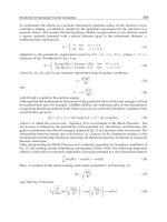
Typical experimental results are exemplified in Fig.5, where the heat transfer coefficient
distributions in a tube for different inlet qualities are displayed by h (= q
w
/(T
w
-T
s
)) versus
x
E
. For subcooled (run no.1) and low quality (run no. 2) inlet condition the post-CHF region
initiates with IAFB followed by DFFB. While for relatively high inlet quality (run no. 3 and
4) the DFFB covers the whole post-CHF region. As seen, lower heat transfer coefficients are
attained in the transition region.
-0.10.00.10.20.30.40.50.60.70.8
0
100
200
300
400
500
EQ model
(D = 12mm, L = 2.6m)
G = 98 kg/m
2
s
P = 0.12 - 0.18 MPa
run q
w
(W/cm
2
)
h = q
w
/(T
w
-T
s
) (W/m
2
K)
X
E
1 4.7
2 4.2
3 5.6
4 7.9
Fig. 5. Distributions of the heat transfer coefficients along the length for different inlet
qualities
3.1 Inverted annular film boiling
In IAFB the heat is transferred by convection and radiation from the wall to the vapor,
subsequently from the vapor to the interface with liquid. For subcooled condition it is then
partially transferred to the liquid core. At the interface the vaporization takes place and the
vapor generation rate is determined by the heat flux to the interface minus that to the liquid
core. As the increase of vapor generation the vapor flow in the film may transit from
laminar to turbulent. Furthermore, the interaction between two phases could result in
interface oscillation, having enhancement effect on the heat exchange in both the vapor film
and the liquid core.
3.1.1 Effects of the pressure, mass flux and subcooling
Fig.6 shows the distributions of heat transfer coefficients (h = q
w
/(T
w
-T
s
)) under different
conditions. For lower flow with higher subcooling the h decreases rapidly with distance,
while as subcooling decreasing the h decreases, and the trend becomes mild (Fig.6(a)). For
higher flow with higher subcooling a maximum h is attained at a few centimeters from the
dryout point (Fig.6(b,c)). In this case the thickness of vapor film is very small, so the
interface oscillation could lead to dry-collision between liquid and wall, resulting in a
substantial increase in the h. For low inlet subcooling the variation of h along the length is
not substantial (Fig.6(f)). This suggests that as the distance increases the negative effect of
the increase in thickness and the positive effect of disturbance in the vapor film are
comparable on the heat transfer.
Heat Transfer - Theoretical Analysis, Experimental Investigations and Industrial Systems
240
At higher pressure the heat transfer coefficients are generally higher than those at lower
pressure for low subcooling or saturation condition (Fig. 6(e, f). An opposite effect is
observed for higher flow and higher subcooling (Fig. 6(d)). This can be explained in terms
of the thickness of vapor film and the interface oscillation. Higher pressure corresponds
to smaller volumetric vapor generation and thus smaller thickness of the film.
(a) (b) (c)
(d) (e) (f)
Fig. 6. Variation of the heat transfer coefficient in IAFB under different conditions (Chen, 1987)
Heat Transfer in Film Boiling of Flowing Water
241
It results in higher h for low subcooling or saturated condition. Nevertheless at higher flow
and higher subcooling the film is very thin, and for lower pressure there could exist stronger
interface oscillation, even dry-collision of liquid to wall, which has predominant effect on
the heat exchange in both the vapor film and the liquid core. While for higher pressure this
effect is less important due to less interface oscillation.
3.1.2 Effect of the preceding heating
To clarify the effect of preceding heating, an additional power supply was provided to a
section of L = 225 mm immediately ahead of AB (with heat flux q
0
). When the q
0
exceeded a
value for the onset of boiling a substantial fall in the T
w
was attained over the first about 100
mm for fixed p, G and ∆T
s
at the dryout point, as shown in Fig.7 (Chen, 1987). In this case a
bubble layer was produced upstream, which was determinant for the vapor flow rate and
the interfacial oscillation over a certain length near the dryout point. For high subcooling the
vapor film was very thing, and this effect could be more substantial. Nevertheless, at a q
0
without boiling the T
w
near the dryout point was increased slightly. In this case a
temperature profile was developed in the subcooled liquid core, which would result in
lower heat transfer coefficient from the interface to liquid core, compared to that with
uniform core temperature for the same average temperature.
Fig. 7. Effect of the preceding heating power on the wall temperature (Chen, 1987)
3.2 Dispersed flow film boiling
In DFFB the heat is transferred from the wall to the vapor, then from the vapor to the liquid
droplets entrained in the continuous vapor flow. The wall temperature is mainly dominated
by the vapor convection heat transfer and the vapor temperature. The liquid droplets would
induce some disturbance for the vapor convection, and the vapor-droplet interfacial heat
Heat Transfer - Theoretical Analysis, Experimental Investigations and Industrial Systems
242
transfer determines the vapor temperature. This effect is closely relative with the flow
conditions, associated with complicated parametric trends of the wall temperature.
3.2.1 Effects of the pressure, mass flux and inlet quality
Typical distributions of the h (= q
w
/(T
w
-T
s
)) along the length are shown in Fig.8. In general,
as distance increases from the dryout point, at first the h decreases rapidly. For lower flow it
decreases monotonously over the whole length, though the trend becomes milder
downstream. For higher flow the h turns to increase after a certain distance. This behavior
varies distinctly with pressure. At p < 0.2 MPa , for instance, the increase trend in the h is
observed at mass flux below 300 kg/m
2
s, while for higher pressure it is attained at higher
mass flux.
In addition to the local parameters, p, G and x
e
, the inlet quality (at the dryout point) has a
significant effect on the h. As seen, for the same pressure and mass flux with different inlet
quality, different h may be attained at a fixed local x
e
, and higher h corresponds to higher
inlet quality, exhibiting a strongly history-dependent feature. This is understandable due to
the fact that to reach a same x
e
the flow with higher inlet quality subjects to less heat transfer
and thus less superheat of vapor. At low flow this effect is so significant, that the fully-
developed condition can not be reached even at L > 2 m or L/D > 200.
(a) (b)
(c) (d)
Heat Transfer in Film Boiling of Flowing Water
243
(e) (f)
(g) (h)
Fig. 8. Variations of heat transfer coefficient for different conditions in DFFB (— mechanistic
model), (a-f): DFFB covering the whole post-CHF region; (g,h): DFFB preceded by IAFB
(Chen et al., 1991, 1992, 1994b)
0.05 0.10 0.15 0.20 0.25 0.30
450
500
550
600
650
700
(D = 12 mm, L = 2.2 m)
G = 420 kg/m
2
s
p = 5.2 - 5.5 MPa
q (W/cm
2
)
h = q
w
/(T
w
-T
s
) (W/m
2
K)
X
E
19.8
16.7
12.9
0.10 0.12 0.14 0.16 0.18 0.20 0.22 0.2
4
0
20
40
60
80
100
120
140
160
(D = 12 mm), L = 2.2 m
G = 103 kg/m
2
s
p = 0.57 MPa
q (W/cm
2
)
h = q
w
/(T
w
- T
s
) (W/m
2
K)
X
E
4.1
3.1
(a) (b)
Fig. 9. Effect of heat flux on the heat transfer coefficients in DFFB
Heat Transfer - Theoretical Analysis, Experimental Investigations and Industrial Systems
244
3.2.2 Effects of other factors
The effect of heat flux on the h is shown in Fig.9. Higher heat flux corresponds to higher h.
This is mainly attributed to the increase in the radiation heat transfer due to higher wall
temperature at higher heat flux. Fig.10 shows the effect of diameter on the h. In general,
smaller diameter corresponds to lower heat transfer coefficients over the downstream. It is
expectable that for same heat flux and mass flux smaller diameter corresponds to greater
increase rate of the enthalpy along the length, leading to stronger thermal non-equilibrium
and thus lower h.
0.20 0.25 0.30 0.35 0.40 0.45 0.50 0.55 0.60
0
40
80
120
160
200
240
q
w
= 6.8 W/cm
2
x
DO
= 0.23
p = 0.15 MPa
G (kg/m
2
s)
92.7
98.2
h = q
w
/(T
w
-T
s
) (W/m
2
K)
X
E
D = 12 mm
D = 6.7 mm
0.05 0.10 0.15 0.20 0.25 0.30 0.3
5
200
300
400
500
600
700
5.7
5.4
p (MPa)
q
w
= 17 W/cm
2
G = 421 kg/m
2
s
h = q
w
/(T
w
-T
s
) (W/m
2
K)
X
E
D = 12 mm
D = 6.7 mm
(a) (b)
Fig. 10. Effect of diameter on the heat transfer coefficients in DFFB
3.2.3 Thermal non-equilibrium
The complicated parametric trends of the heat transfer in DFFB are closely related to the
thermal non-equilibrium, which is determined by the fraction of total heat to the vapor for
superheating. The following thermal non-equilibrium parameter was defined by Plummer
et al. (1977),
0
0e
xx
K
xx
−
=
−
(1)
with
1
()
1
pg v s
e
fg
CTT
xx
h
−
⎛⎞
−
⎜⎟
=+
⎜⎟
⎝⎠
where the
v
T
and
s
T
are the vapor temperature and saturation temperature, respectively, the
x
0
is the quality at the dryout point, and the x and x
e
are the local actual quality and
equilibrium quality, respectively.
Heat Transfer in Film Boiling of Flowing Water
245
The case of K = 1 represents the thermal equilibrium, in which all the heat from the wall
goes to liquid for evaporation and the vapor temperature keeps at constant (T
s
), so the h
increases along the length as the vapor flow rate increasing. The case of K = 0 represents that
all the heat goes to the vapor for superheating without vapor generation, so the
w
T increases
as the
v
T increasing and thus the h decreases monotonously. Fig.11 illustrates the substantial
effect of the K on both the values and the trends of the heat transfer coefficient.
Using a technique to prevent the probe from striking by the liquid droplets and from the
effect of radiation, the data of vapor superheat were successfully obtained in steady-state
film boiling experiments near the exit of test section (Chen, 1992, Chen & Chen, 1994a). The
values of K and ratio of (T
v
-T
s
)/(T
w
-T
s
) were then evaluated from the vapor superheats
measured at 2 m from the dryout point, as shown in Fig.12. For low X
0
, the K decreases as X
0
increasing. At certain increased X
0
the trend becomes milder. It varies distinctly with
pressure, and higher K is attained at lower pressure. The ratio (T
v
-T
s
)/(T
w
-T
s
) decreases with
mass flux. For G < 100 kg/m
2
s, the (T
v
-T
s
)/(T
w
-T
s
) is larger than 0.5, suggesting a major
contribution of the vapor superheat to the wall superheat. For G < 50 kg/m
2
s the thermal
non-equilibrium is much significant, so that the T
v
and T
w
increase significantly along the
length, and the h (= q
w
/(T
w
-T
s
)) exhibits sharp decrease trend. The effects of various
parameters on the thermal non-equilibrium can be explained in terms of droplet size and
concentration, the vapor-droplet relative velocity and heat transfer coefficient, the
properties, etc This is made clear in the analysis with the two-fluid mechanistic model.
Fig. 11. Variations of the heat transfer coefficient along the length for different K (p = 5.8
MPa, G = 417 kg/m
2
s, x
DO
=0.383, D=6.8mm) (Chen, et al., 1992)
Heat Transfer - Theoretical Analysis, Experimental Investigations and Industrial Systems
246
Fig. 12. Variations of the K with x
0
and (T
v
-T
s
)/(T
w
-T
s
) with G for different conditions
(Chen & Chen, 1994a, Chen, et al., 1992)
3.3 Minimum film boiling temperature
The minimum film boiling temperature, T
min
, defines the boundary between the film boiling
and the transition boiling, in which the wall contacts with the liquid intermittently and thus
has much higher heat transfer coefficient than the film boiling. The collapse of film boiling
could be resulted from the thermodynamic limit or the hydrodynamic instability. During a
fast transient it could be thermodynamically controlled, while for low flow and low pressure
it is likely to be hydraudynamically controlled. Six types of the film boiling termination
mechanisms have been identified: (1) collapse of vapor film, (2) top flooding, (3) bottom
flooding, (4) droplet cooling, (5) Leidenfrost boiling and (6) pool boiling. Significant
discrepancies were found among the existing correlations of the T
min
, and were attributed to
the different types of the mechanism and scarcity of reliable data (Groeneveld & Snoek, 1984).
With the hot patch technique the minimum film boiling temperatures were measured in
steady-state film boiling experiments by decreasing the power to the test section slowly with
small steps until the collapse of film boiling occurred. The following empiric correlation was
formulated from an experiment over the ranges of p = 115 – 6050 kPa, G = 53 – 1209 kg/m
2
s,
x = -0.055 – 0.08 and ∆T
s
= -35 – 25.1 K (Chen, 1989),
Heat Transfer in Film Boiling of Flowing Water
247
62
min
363,6 38.37ln 0.02844 3.86 10T
pp p
aTs
Δ
−
=+ + −× + (2)
with
17.1 /(3.3 0.0013 )ap
=
+ for 0Ts
Δ
>
and 0a
=
for 0Ts
Δ
≤
where the
p
is in kPa and the
min
T and △T
s
in K.
This correlation is in reasonable agreement with that derived from a similar experiment by
Groeneveld and Steward (1982). It can be recommended for type (1-4) of film boiling
termination.
4. Predictions for the heat transfer coefficients
As described above, the film boiling is characterized by non-equilibrium in both the velocity
and temperature between phases, associated with extremely complicated parametric trends.
The steady-state experimental data obtained in tube with flowing water were compared with
the existing correlations, and significant discrepancies were observed between them, as shown
in Fig.13. This result revealed the suspect of the correlations, and it was attributed to the lack
of reliable data base and the difficulty in accounting for various physical mechanisms in a
simple correlation (Stewart and Groeneveld, 1982, Groeneveld & Snoek, 1984). With steady-
state technique the accuracy of the experimental data was improved substantially. As shown
in Fig.14, the present steady-state data are in well agreement with those obtained by
Swinnerton et al (1988) using indirectly heated hot patch technique for similar conditions.
(a) (b)
Fig. 13. Comparison of the steady-state experimental data of water with existing correlations
(Stewart and Groeneveld, 1982)
Heat Transfer - Theoretical Analysis, Experimental Investigations and Industrial Systems
248
To predict the non-equilibrium characteristics in film boiling the two-fluid models are
favorable, and have been proposed by many investigators (Groeneveld, 1988, 1992, Mossad
& Johannsen, 1989). The major challenge for these models is to simulate the interfacial heat
and momentum exchanges. Due to less knowledge on these processes they were generally
accounted by empiric or semi-empiric correlations. Therefore, the suitability of this kind of
models is heavily determined by the ranges and the accuracy of data base. The following
two-fluid models are developed based on the present experimental data.
0.02 0.04 0.06 0.08 0.10 0.12
200
250
300
350
p G q
w
MPa kg/m
2
s W/cm
2
h = (q
w
/(T
w
-T
s
) (W/m
2
K))
X
E
1.0 219 9.3
1.0 190 9.5
0.02 0.04 0.06 0.08 0.10 0.12 0.14 0.16
80
120
160
200
240
h = (q
w
/(T
w
-T
s
) (W/m
2
K))
0.49 96 5.5
0.48 102 6.0
p G q
w
MPa kg/m
2
s W/cm
2
X
E
(a) (b)
Fig. 14. Comparison of the results obtained in different steady-state experiments with water
flowing in tube (
— Swinnerton, et al.D=9.75mm, ● Present experiment, D=12mm)
4.1 IAFB model
The schematic of flow structure in IAFB is shown in Fig.15, in which the vapor film is
divided into two regions, A and B, bounded with the locus of the maximum velocity line.
Fig. 15. Inverted annular film boiling mode
Heat Transfer in Film Boiling of Flowing Water
249
The assumptions are as follows:
•
The pressure over a cross section is uniform.
•
The kinetic energy and viscous dissipation and pressure loss due to acceleration are
negligible.
•
The properties of vapor are evaluated at ()/2
ws
TT
+
.
•
The vapor-liquid interface is treated as smooth, and both the vapor and the liquid at the
interface are at saturation.
•
The velocity profile in the liquid core is uniform and equal to the vapor velocity at the
interface.
In vapor film the force balance gives
22
0
(1 ) ( ) 0
2
v
vv
v
dp
rr
du
g
dr r dz
ε
μρ
ν
−
+
++=
(3)
with boundary conditions as
0u
=
at
2
rr
=
and
il
uu u
=
= at
i
rr
=
where
l
u is the average velocity in the core.
Neglecting the weight of vapor, the integration of Eq.(3) gives,
for region A
222
02
2
11
ln ( )
2(1 /) 2
g
vvv
dp
r
urrr
dz r
μεν
⎡⎤
=+−
⎢⎥
+
⎣⎦
(4)
and for region B
222
01
1
11
ln ( )
2(1 /) 2
g
i
vvv
dp
r
urrru
dz r
μεν
⎡⎤
=
−−+
⎢⎥
+
⎣⎦
(5)
with
222
101
2
0
()
cv
d
p
r
g
rr
g
dz
r
ρ
ρ
+−
=
(6)
where
v
ε
is the eddy diffusivity in the vapor film, and the
c
ρ
is the average density of the
core. Some vapor may be entrained in the core, and
c
ρ
is evaluated by
(1 )
ccv cl
ρ
αρ α ρ
=
+−
where
c
α
is the void fraction of the core. The following expression is attempted with
adjustable factor c=40,
1
1//
c
vl
cx
α
ρρ
=
+
Assuming the momentum eddy diffusivity
v
ε
independent of r, by integrating Eq. (4) and (5)
the vapor flow rate in the film is as
Heat Transfer - Theoretical Analysis, Experimental Investigations and Industrial Systems
250
4
44 222 22
0
2
21 021 01
1
11
ln()() ()
(1 / ) 2 8 2
v
iv
vvv
dp
r
r
rr rrr u rr
dz r
πρ
Γπρ
μεν
⎡⎤
=+−−−+−
⎢⎥
+
⎢⎥
⎣⎦
(7)
The wall heat flux is expressed as
,,wic wir v
qq q q
−−
=
++ (8)
where
v
q is the heat for vapor superheating,
,wic
q
−
and
,wir
q
−
are the heat flux to the
interface by convection and by radiation, respectively, evaluated by,
,
()
wic c w s
q
hT T
−
=
− (9)
with
Pr
(1 )
Pr
vvv
c
vt
k
h
ε
δν
=+ (10)
and
44
,
0.75 ( )
(1/ 1/ 1)
SB
wir w s
lw
qTT
σ
εε
−
=−
+−
(11)
where
δ
is the thickness of film, and Pr
t
is the turbulent Prandtl number.
The energy balance equation at the interface can be written as,
,,wic wir
g
l
qqqq
−−
+
=+
where
l
q
is the heat flux from the interface to the core, and
g
q
is the heat flux for
evaporation, as
1
/2
gfg
d
qhr
dz
Γ
π
=
(12)
The mass equation is written as
22
12c
ru rG
Γπ ρ π
+= (13)
From the authors experiments with saturated and low subcooling condition, the following
empiric expression for
v
ε
is proposed with Pr
t
=1.0.
0.6 0.3
/ 0.011Re Re
vv v l
εν
= (14)
with
21
Re 2 ( ) /
vv
Gx r r
μ
=
−
and
1
Re (1 ) /
ll
GxD
μ
=−
For the heat transfer from interface to subcooled liquid core the following correlation is
available (Alalytis & Yadigaroglu 1987)
Heat Transfer in Film Boiling of Flowing Water
251
[]
0.15
0.6 0.3 0.6
0.06( / )Re Pr /( ) Pr ( )
llllvvllv
f
q
kD TsT
μρ μρ
−
=− (15)
It should be noted that for subcooled condition the h near the dryout point is related to the
condition at the dryout point, which is determined by the preceding heating, as described
above. It is not simulated in the model, therefore, the calculation result could have
appreciable uncertainty over a short length, especially for high subcooling.
For low subcooling and saturated condition, this model gives satisfactory calculations for
the experimental data of p = 0.1 – 6 MPa, and G = 90 – 1462 kg/m
2
s, as exemplified in
Fig.6(f).
4.2 DFFB model
The following two-fluid mechanistic model is based on the motion and energy equations,
involving various equations for the wall-vapor-droplet heat transfer (Chen & Chen, 1994b).
The heat from the wall, q
w
, is transferred to the vapor by convection, q
c
, and radiation, q
r
, as
wcr
qqq
=
+
(16)
with
()
ccwv
qhTT
=
− (17)
and
44
()
rSBwv
q
TT
εσ
=−
(18)
where
c
h is the convective heat transfer coefficient,
SB
σ
is the Boltzman’s constant, and
ε
the
emissivity.
The vapor temperature is evaluated by
(1)
fg
e
vs
p
v
h
x
TT
xC
=+ −
(19)
where x and x
e
are the actual quality and equilibrium quality, respectively.
From the heat balance equation, we have
"
6(1 )
d
lfgl
x
q
dx
dz u h
ρ
δ
−
=
(20)
where
l
u and
δ
are the droplet velocity and diameter, respectively. The heat flux to the
droplet,
"
d
q
, includes the convective and radiative components, i.e.,
"
,,ddcdr
qq q=+ (21)
with
44
,
()
dr SB w s
qETT
σ
=− (22)
and
2
3(1 )
E
D
δ
ε
α
=
−
Heat Transfer - Theoretical Analysis, Experimental Investigations and Industrial Systems
252
The vapor to droplet convective heat transfer is evaluated by Frossling correlation, as
" 0.5 0.33
,
()
(2 0.552( ) Pr )( )
vvvl
dc v v s
v
kuu
q
TT
ρδ
δμ
−
=+ − (23)
The motion equation for the droplet gives
2
()
3
()
22
ldvvl
ll l v
du C u u
u
g
dz
ρ
ρρρ
δ
−
=−− (24)
where the drag coefficient,
d
C , is evaluated by Ingebo’s correlation, as
0.75
24(1 0.1Re )
Re
d
d
d
C
+
= for Re 1000
d
<
with
()
Re
vv l
d
v
uu
ρ
δ
μ
−
=
and
0.45
d
C
=
for Re 1000
d
≥
The wall to vapor convective heat transfer is predicted by the correlation derived from an
author’s convection heat transfer experiment in pure steam, multiplying an enhancement
factor due to the disturbance induced by the droplets, as
0c
hhF
=
(25)
with
,,
0.812 0.33
0,
,
0.0175 ( ) Pr
vf vf v
v
f
vf
kuD
h
D
ρ
μ
=
The factor
F
would be related with pressure and quality. To fit the calculations with the
experimental results, the following expression for
F is proposed with p in MPa, as
12
2.32(1 0.1 ) 1
x
Fpe
−
=
++
For the DFFB occurring from the dryout of liquid film of annular flow, the initial droplet
diameter,
0
δ
, is evaluated by a modification of Nujiyama-Tanazawa equation, as
0.5
0
00
798 ( ) ( )
a
vv
l
Gx Gx D
ρμ
σ
δ
ρ
= (26)
where
0.63 0.1ap
=
− for 1.3
p
MPa
<
Heat Transfer in Film Boiling of Flowing Water
253
and
0.5a
=
for 1.3
p
MPa≥
in which p is in MPa,
δ
and
D
in m, G in kg/m
2
s,
μ
in kg/ms,
σ
in kg/m,
l
ρ
and
v
ρ
in
kg/m
3
.
The droplet has a maximum diameter, determined by the critical Weber number,
c
We , as
2
()
c
m
vv l
We
uu
σ
δ
ρ
=
−
(27)
with
c
We
= 5.0.
For the DFFB occurring from the break-up of the IAFB, the initial diameter
0
δ
is taken
as
m
δ
. The onset of DFFB is defined by the criterion of droplet carryover (Yanomoto et al.,
1987), as
1/4 1/6
3.57
(( ))
g
cl
gg
gd
JgN
C
μ
σρ ρ
ρ
=− (28)
with
1/2
()
g
g
g
lg
N
g
μ
μ
σ
ρσ
ρρ
=
⎡
⎤
⎢
⎥
−
⎢
⎥
⎣
⎦
where
g
c
J is critical volumetric flux and
g
N
μ
is viscosity number.
Assuming that the droplet break-up does not occur, so it varies with the actual quality, as
1/3
0
0
1
()
1
x
x
δδ
−
=
−
The present model gives satisfactory predictions for the DFFB data over the range of
pressure of 0.1 – 6 MPa, mass flux of 23 – 1020 kg/m
2
s, as exemplified in Fig.8.
4.3 Tabular method
The film boiling models and phenomenological equations are time consuming, because they
involve a large number of constitutive equations on the heat and momentum exchanges
between phases and the evaluations of many properties. Furthermore, they are only
applicable for the specific test condition of individual investigator. In recent years, the
tabular method has been widely accepted due to its advantages of high accuracy, wide
applicable range and convenience for application and updating.
4.3.1 fully-developed film boiling heat transfer coefficients
Based on over 15000 film boiling data points, Leung et al. (1997) have developed a look-up
table for the fully-developed film boiling heat transfer coefficients in tubes with vertical
upward flow. It contains a tabulation of normalized heat transfer coefficients at discrete
local parameters of pressure (0.1 – 20 MPa in 14 steps), mass flux (0 – 7000 kg/m
2
s in 12