ADVANCED ONSITE WASTEWATER SYSTEMS TECHNOLOGIES - CHAPTER 4 ppt
Bạn đang xem bản rút gọn của tài liệu. Xem và tải ngay bản đầy đủ của tài liệu tại đây (856.32 KB, 22 trang )
© 2006 by Taylor & Francis Group, LLC
115
chapter four
Aerobic treatment units
Introduction
Although aerated wastewater treatment has been used since the 1800s in the
form of media filters, suspended growth aerated treatment is relatively mod-
ern. The first activated sludge treatment plant began operation in 1916 in
San Marcos, Texas. A channel aeration treatment system was constructed in
Sheffield, England in 1921 (Dinges, 1982).
Naturally occurring microorganisms are the workhorses of wastewater
treatment. Sometimes mistakenly considered to be "merely bacteria," the
ecosystem of a suspended growth aerated treatment system includes bacte-
ria, fungi, protozoa, rotifers, and other microbes. These organisms thrive on
many of the complex compounds contained in domestic wastewater. Sec-
ondary-treatment activated sludge processes are highly engineered bioreac-
tors. These bioreactors are designed to provide microbes with the optimum
conditions to assist in the renovation of domestic wastewater. With the
mechanical addition of dissolved oxygen, aerobic and facultative microbes
can rapidly oxidize soluble, bioavailable organic and nitrogenous com-
pounds.
Onsite and decentralized wastewater management systems take advan-
tage of this technology. Aerobic treatment units can be an option when
insufficient soil is available for the proper installation of a traditional septic
tank and soil absorption area. Increasingly, homes and small commercial
establishments are being constructed in rural areas with no central sewer
and on sites with marginal soils. In these situations, wastewater must receive
a high level of pretreatment before being discharged into the soil environ-
ment. Depending on local regulations, the use of an aerobic treatment unit
may allow for a reduction in the required infiltration area or a reduction in
depth to a limiting soil layer. This ability to produce high-quality effluent
may open sites for development that were previously unsuitable because of
soil limitations (U.S. Environmental Protection Agency [EPA], 2000).
Although all wastewater treatment devices that are engineered to main-
tain aerobic conditions are considered "aerobic treatment units," the commu-
© 2006 by Taylor & Francis Group, LLC
116 Advanced onsite wastewater systems technologies
nity of onsite wastewater management professionals divide these devices
into two classifications: saturated (with wastewater) and nonsaturated.
Whether suspended-growth or attached-growth, any unit that maintains
saturated and aerobic conditions is generally referred to as an ATU — the
acronym for "aerobic treatment unit." In this chapter, the term ATUs refers
to an engineered, suspended growth, high-rate wastewater treatment pro-
cess. In nonsaturated, attached-growth systems, atmospheric oxygen is pas-
sively transferred into a dissolved state as the water moves around or
through the media. Trickling filters (such as those found at smaller municipal
wastewater treatment plants) and most packed-bed filters typify this type
of biological process.
The classical expectation of an ATU is to reduce the concentration of
soluble organic compounds and suspended solids. Like manufacturers of
media filters, manufacturers of ATUs are actively developing new treatment
systems that incorporate enhanced disinfection and nitrogen and phospho-
rus removal as parts of the treatment train.
Theory of biochemical wastewater treatment using aerobic treatment
processes
Most people consider bacteria and other microorganisms undesirable dis-
ease-causing components of wastewater. In fact, only a small fraction of the
microbes found in wastewater are truly pathogenic. Aerobic wastewater
treatment encourages the growth of naturally occurring aerobic microorgan-
isms as a means of renovating wastewater. Such microbes are the engines of
wastewater treatment plants. Organic compounds, high-energy forms of
carbon, are the fuel that powers these engines. The work of the engines is
to oxidize organic compounds to a low-energy form (carbon dioxide). The
final products of the process are carbon dioxide, water, and more microor-
ganisms. One way to represent this process is:
Organic carbon + oxygen + microbes →
carbon dioxide + water + more microbes (4.1)
Understanding how to mix aerobic microorganisms, soluble organic com-
pounds, and dissolved oxygen for high-rate oxidation of organic carbon is
one of the fundamental tasks of wastewater engineering.
Microorganisms responsible for the oxidation of complex organic com-
pounds are called decomposers. These organisms return simple forms of car-
bon back to the soil, water, and atmosphere. When high concentrations of
organic pollutants are available, these decomposers flourish. Because these
same microorganisms exist in natural water bodies, wastewater being dis-
charged back into surface water bodies must have a very low organic
strength. Natural aquatic systems must have an ample concentration of
dissolved oxygen to support advanced life forms, such as fish and macroin-
vertebrates. Most decomposing microbes prefer aerobic conditions to anaer-
© 2006 by Taylor & Francis Group, LLC
Chapter four: Aerobic treatment units 117
obic conditions. When dissolved oxygen is available, the aerobic decompo-
sition of organic compounds consumes dissolved oxygen out of the water.
If the rate of re-aeration is not equal to the rate of consumption, the dissolved
oxygen concentration falls below the level needed to sustain a viable aquatic
receiving environment. The level of treatment and the receiving environment
should be considered as a holistic system of evaluation when choosing an
appropriate treatment system to suit a site.
The concentration of soluble, bioavailable organic compounds in water
is often measured as biochemical oxygen demand, or BOD. As previously
described, oxygen demand is the result of aerobic microorganisms consum-
ing dissolved oxygen as they decompose organic carbon and nitrogen com-
pounds. In the engineered biochemical oxidation of wastewater, oxygen is
supplied to aerobic microorganisms so that they will consume the substrate
(organic carbon and nitrogen compounds) to fuel their metabolism. The
result is the conversion of organic pollutants into inorganic compounds and
new microbial cells as illustrated in Equation 4-1. The net production of cells
(creation of new cells versus the die off of old cells) forms an accumulation
of biological material.
Organic materials that are typically found in residential strength waste-
water include carbohydrates, fats, proteins, urea, soaps, and detergents. All
of these compounds contain carbon, hydrogen, and oxygen. Domestic waste-
water also includes organically bound nitrogen, sulfur, and phosphorus.
During biochemical degradation, these three elements are biologically trans-
formed from organic forms to mineralized forms (i.e., NH
3
, NH
4
, NO
3
, SO
4
,
and PO
4
).
Microbial metabolism
Metabolism is the sum of the biochemical processes that are employed in
the destruction of organic compounds (catabolism) and in the buildup of
cell protoplasm (anabolism). These processes convert chemically bound
energy into energy forms that can be used for life-sustaining processes.
Catabolism is an oxidative, exothermic, enzymatic degradation process that
results in the release of free energy from the structures of large organic
molecules. Some of the released energy is available for construction of new
cellular material. Anabolism is a synthesis process that results in an increase
in size and complexity of organic chemical structure (Benefield and Randall,
1985).
Fermentation and respiration
Aerobic and anaerobic heterotrophic microorganisms use the fermentation
process to reduce complex organic compounds to simple organic forms.
Heterotrophs are microorganisms that use organic carbon for the formation
of new biomass. These organisms are consumers and decomposers and
system. As mentioned in Chapter 2, this is another consideration of the
© 2006 by Taylor & Francis Group, LLC
118 Advanced onsite wastewater systems technologies
therefore depend on a readily available source of organic carbon for cellular
synthesis and chemical energy. They are the primary workhorses in the
oxidation of soluble BOD in wastewater treatment. In comparison,
autotrophic microorganisms can create cellular material from simple forms
of carbon (such as carbon dioxide). These organisms are at the bottom of the
food chain. They do not depend on other organisms for the creation of
complex organic compounds. Autotrophic microorganisms are important for
the removal of nitrogen from wastewater.
As shown in equation 4.2, fermentation is an exothermic, enzymatic
breakdown of soluble organic compounds and does not depend on the
presence of dissolved oxygen. Fermentation is often described in two stages:
acid fermentation and methane fermentation. End products of the acid fer-
mentation process include volatile fatty acids (VFAs) and alcohols. Little
reduction in BOD occurs because most of the carbon is still in organic form.
During methane fermentation, a portion of the acid-fermentation end prod-
ucts are converted to methane and carbon dioxide gases. The result of this
conversion is a reduction in BOD. Anaerobic microorganisms are limited to the
fermentation process. This is why methane can only be produced with anaer-
obic conditions.
(4.2)
Through the process of respiration, aerobic microorganisms can further
transform VFAs (and other bioavailable organic compounds) into carbon
dioxide, water, and additional energy (Lehninger, 1973). As shown in equa-
tion 4.3, respiration requires the presence of oxygen, typically dissolved
oxygen in the mixed liquor of a suspended-growth (activated sludge) system.
Oxygen acts as an electron acceptor for the catabolic degradation of VFAs.
Because aerobic microbes can readily convert bioavailable organic carbon
into inorganic carbon, aerobic systems can provide high-rate wastewater
treatment.
(4.3)
COHNS
organic compounds
heterotrophic
microbees
volatile
fatty
acids
+
⎯→⎯⎯⎯⎯⎯
⎡
⎣
⎢
⎢
⎢
⎤
⎦
⎥
⎥
⎥
CO + H O + CH + energy + residu
22 4
aals
volatile
fatty
acids
+O
aerobic
2
⎡
⎣
⎢
⎢
⎢
⎤
⎦
⎥
⎥
⎥
mmicrobes
energy + CO + H O +
22
⎯→⎯⎯⎯⎯ residuals
© 2006 by Taylor & Francis Group, LLC
Chapter four: Aerobic treatment units 119
Biosynthesis
According to Lehninger (1973), biosynthesis is the most complex and vital
energy-requiring activity of all living organisms. As shown in equation 4.4,
biosynthesis is the formation of characteristic chemical components of cells
from simple precursors and the assembly of these components into struc-
tures, such as membrane systems, contractile elements, mitochondria, nuclei,
and ribosomes. Two kinds of ingredients are required for the biosynthesis
of cell components: precursors that provide the carbon, hydrogen, nitrogen,
and other elements found in cellular structures and adenosine triphosphate
(ATP) and other forms of chemical energy, which are needed to assemble
the precursors into covalently bonded cellular structures.
(4.4)
As seen in equation 4.4, cell composition can be represented as
C
60
H
87
N
12
O
23
P. If phosphorus is not considered, basic cell composition is
often written C
5
H
7
NO
2
. It is important to reinforce the point that the cellular
components are being taken from a wastewater stream and thus, many
wastewater constituents are converted into new cells. Table 4.1 lists the
typical composition of bacterial cells.
Endogenous Respiration
Under substrate-limited conditions, microbes feed on each other at a higher
rate than new cells can be produced. The aerobic degradation of cellular
material is endogenous respiration (Equation 4.5). Endogenous respiration
is not 100% efficient and thus slowly degradable cellular material and other
residuals accumulates (Reynolds, 1982). ATUs employed in the decentralized
Table 4.1 Percent Elemental Composition of Cellular Material
Carbon 50.0 Potassium 1.0
Oxygen 22.0 Sodium 1.0
Nitrogen 12.0 Calcium 0.5
Hydrogen 9.0 Magnesium 0.5
Phosphorus 2.0 Chlorine 0.5
Sulfur 1.0 Iron 0.2
Other trace elements including
Zn, Mn, Mo, Se, Co, Cu, and Ni:
0.3
Source: Adapted from Metcalf & Eddy, Inc. (2003).
simple
precursors
microbes
energy
⎯→⎯⎯⎯⎯
CHNOP
new cells
60 87 12 23
© 2006 by Taylor & Francis Group, LLC
120 Advanced onsite wastewater systems technologies
wastewater management industry operate in the endogenous respiration
phase. Referred to as extended aeration, this process provides plenty of aera-
tion to ensure that microbes will start feeding on each other once food is
consumed. This effect minimizes the accumulated biomass that must be
removed by the maintenance provider.
(4.5)
Environmental factors
In order to provide high-rate oxidation of organic pollutants, microorgan-
isms must be provided with an environment that allows them to thrive.
Temperature, pH, dissolved oxygen and other factors affect the natural selec-
tion, survival, and growth of microorganisms and their rate of biochemical
oxidation.
Temperature
The rate of bio-oxidation is a function of temperature. Various microbial
species have optimal temperatures for survival and cell synthesis:
• Psychrophilic microorganisms thrive in a temperature range of -2°
to 30°C (28° to 86°F). Optimum temperature is 12° to 18°C (54° to
64°F).
• Mesophilic microorganisms thrive in a temperature range of 20° to
45°C (68° to 113°F). Optimum temperature is 25° to 40°C (77° to
104°F).
• Thermophilic microorganisms thrive in a temperature range of 45°
to 75°C (113° to 167°F). Optimum temperature is 55° to 65°C (131° to
149°F).
Overall, as temperature increases, so does microbial activity. Generally
speaking, decentralized ATUs are buried and the soil acts as a sink for the
heat generated by the exothermic activity within the treatment unit. The
microbial population in a buried ATU consists of a mixture of psychrophilic
and mesophilic organisms.
Food-to-microorganism ratio
The food-to-microorganism ratio (F/M) represents the mass of bioavailable
organic compounds (substrate) loaded into the aeration chamber each day
in relation to the mass of microorganisms contained within the aeration
CHNOP
cellular material
+O
aero
60 87 12 23
2
bbic
microbes
CO + H O + PO +
22 4
⎯→⎯⎯⎯⎯ NNH + residuals
3
© 2006 by Taylor & Francis Group, LLC
Chapter four: Aerobic treatment units 121
chamber. Typically, this ratio is expressed in terms of mass of soluble BOD
per day per mass of microbes in the treatment unit (Crites and Tchobano-
glous, 1998). Microbial populations are dynamic and respond to changes in
life-sustaining parameters. A time lag occurs between sudden changes in
organic loading and changes in the microbial population. However, if all
other factors are constant, the population can rapidly increase in response
to increased organic loading. To effectively treat an increased organic load,
the hydraulic retention time of the basin must correspond to the time
required for the population to increase. However, increased organic loading
is often associated with increased hydraulic loading. If a means of flow
equalization has not been provided, then effluent will not have the same
residence time or be exposed to the same concentration of microbes.
Acid concentration
The pH of influent has a significant impact on wastewater treatment. Bene-
field and Randall (1985) report that it is possible to treat organic wastewaters
over a wide pH range; however, the optimum pH for microbial growth is
between 6.5 and 7.5. It is interesting to note that bacteria grow best under
slightly alkaline conditions. Conversely, algae and fungi grow best under
slightly acidic conditions. The response to pH is largely due to changes in
enzymatic activity.
Aerobic treatment unit operation
ATUs are high-rate oxidizers of soluble organic and nitrogenous compounds.
From a biological perspective, ATUs used for individual homes and decen-
tralized systems do not employ any processes that are not currently utilized
in large-scale municipal wastewater treatment plants. The technology unique
to ATUs is the design and packaging of these systems for small-flow situa-
tions. These devices are essentially miniature wastewater treatment plants.
In addition to reducing of BOD via aerobic digestion and the conversion of
ammonia by nitrification, many commercially available ATUs have addi-
tional chambers that promote the removal of nutrients, suspended solids,
and pathogens from effluent. Other unique aspects to the design of ATUs
are the ease of installation at remote locations and the ease of maintenance
for semiskilled maintenance providers. ATUs installed at home sites and
small commercial locations must be dependable and maintenance-friendly.
Process description
Primary treated wastewater enters the aeration unit and is mixed with dis-
solved oxygen and suspended or attached microbes, or both. Primary treat-
ment is provided by a “trash tank,” which is essentially a septic tank that is
sized for a shorter detention time than a standard septic tank. Aerobic
microbes convert organic compounds into energy, new cells, and residual
© 2006 by Taylor & Francis Group, LLC
122 Advanced onsite wastewater systems technologies
matter. As the water moves through the clarifier, a portion of the biological
solids is separated out of the effluent and retained within the ATU. These
biological solids settle back into the aeration chamber, where they serve as
seed for new microbial growth. Settled biomass and residuals accumulate
in the bottom of the chamber and must be periodically removed.
Because biomass creates an oxygen demand, clarification is an important
part of generating high-quality effluent. The soluble BOD of effluent is gen-
erally below 5 mg/L, but the biomass solids that carry over may produce
an effluent BOD of 20 mg/L or greater (Benefield and Randall, 1985). Many
ATUs have a cone-shaped clarifier to promote separation of the biomass. As
the cross-sectional area of upflow increases, fluid velocity decreases. Once
the settling velocity of the biomass is greater than the fluid velocity, the
biomass will no longer move upward (Eikum and Bennett, 1992). During
periods of no flow, the biomass will settle back into the aeration chamber.
Other ATUs may incorporate inline filters to separate the biomass from the
effluent. Such filters require periodic maintenance to remove the buildup of
solids.
In the aerobic process, organic nitrogen and ammonia are converted to
nitrate. Under anoxic conditions (no molecular oxygen), this nitrate is den-
itrified to nitrogen gas. Some ATUs are designed to provide denitrification
as part of their operation. Design modifications include intermittently sup-
plying air and recirculating the nitrified wastewater into the anoxic regions
within the treatment unit.
Typical ATU configurations
Most ATUs operate as intermittent-flow, complete mix tank, constant volume
reactors. The flow is intermittent because influent flow is not continuous.
The contents of the aeration chamber are thoroughly mixed to maximize
contact with dissolved oxygen, microbes, and wastewater. Effluent moves
out of the aeration chamber and into a clarifier. The rate of discharge is
directly related to the rate of inflow. The exception to this generalization is
sequencing batch reactors. As described later in this section, this treatment
device operates in batch mode.
Extended aeration
Most commercially available ATUs operate as extended aeration units.
Extended aeration is characterized by long-term aeration, long detention
matter, the microbes will be forced into the endogenous phase of growth
and will readily consume bioavailable organic carbon, including biomass.
The goal is to balance the mass of new cells synthesized each day with the
mass of cells endogenously biochemically degraded each day. The American
Society of Civil Engineers (ASCE, 1977) suggests that, for a treatment unit
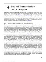
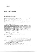
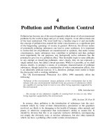
times, low F/M ratio, and low biomass accumulation. As shown in Figure
4.1, by providing plenty of dissolved oxygen and minimal soluble organic
© 2006 by Taylor & Francis Group, LLC
Chapter four: Aerobic treatment units 123
to operate in extended aeration, 2000 cubic ft of air should be injected in the
water per pound of BOD
5
removed.
As shown in Figure 4.1, kinetics of aerobic digestion, as substrate
increases, biomass increases. These curves represent a batch-style application
of substrate, in which biomass concentration changes in response to changes
in substrate concentration. Intermittent-flow, complete mix systems only
operate over a small range on these curves because the concentration of
substrate tends to be relatively constant.
Suspended-growth bioreactors
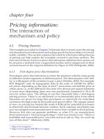
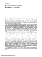
As shown in Figure 4.2, suspended-growth ATUs are scaled-down activated
sludge plants. Activated sludge is a heterogeneous microbial culture com-
posed mostly of bacteria, protozoa, rotifers, and fungi. The bacteria are
responsible for assimilating most of the organic material, whereas the pro-
tozoa and rotifers (serving as predators) are important in removing the
dispersed bacteria that would otherwise escape in ATU effluent (Benefield
and Randall, 1985). The biomass is thoroughly mixed with biodegradable
organic compounds. Individual organisms clump together (flocculate) to
form an active mass of microbes called biological floc (Davis and Cornwell,
Figure 4.1 Kinetics of aerobic digestion.
Figure 4.2 Schematic diagram of a suspended-growth ATU.
Lag
Phase
Growth
Phase
Stationary
Phase
Endogenous
Phase
Time
Biomass Concentration
Concentration
Substrate Concentration
Chamber
Settling
Baffle
Baffle
Sludge
Return
EffluentInfluent
(from Primary Tank)
Maintenance Access
Aeration
Device
(clarifier)
Suspended-Growth
Chamber
© 2006 by Taylor & Francis Group, LLC
124 Advanced onsite wastewater systems technologies
1991). This slurry of biological floc and wastewater is called mixed liquor
(Reynolds, 1982). The concentration of microorganisms in mixed liquor is
measured as mg/L of mixed liquor volatile suspended solids (MLVSS). That
is the volatile suspended solids concentration in the aeration
basin contents.
Reynolds (1982) wrote that the term activated is used to describe the
reactive nature of biological solids. As wastewater enters the aeration cham-
ber, suspended floc adsorbs organic solids and absorbs soluble organic com-
pounds. Through enzymatic activity, the organic solids are solubilized. Once
in solution, the soluble organics are oxidized by biochemical oxidation. At
the inflow of the ATU, the capacity of the biological solids to adsorb and
absorb substrate is rapidly filled. As the mixture moves into the clarification
zone, the biological solids (or "activated" sludge) are re-activated as the
oxidation process proceeds. Near the downstream end of the ATU, the bio-
logical solids are substrate limited and are therefore highly reactive to the
remaining suspended and dissolved organic solids. The extended aeration
process has been shown to run properly at a F/M ratio of 0.042 to 0.153 Lb
of BOD per Lb of MLVSS. Functionally, MLVSS should not fall below 2500
mg/L or exceed 6000 mg/L. Organic loading is typically about 15 Lb BOD
per 1000 cubic feet of volume per day.
Attached-growth bioreactors
Another broad category of ATUs is attached-growth systems. Often called
fixed-film reactors, these systems contain an inert medium for microbial attach-
suspended, colloidal and dissolved organic solids are absorbed by the bio-
logical film. Wastewater and dissolved oxygen are brought in contact with
the attached microorganisms by either pumping the liquid past the media
or by moving the media through the liquid.
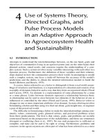
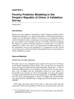
Coupled contact aeration
Treatment units are available that combine attached growth in the same basin
as suspended growth. Referred to as coupled-contact aeration, the combination
of attached-growth and suspended-growth processes enhances the perfor-
mance and capacity of aeration units (U.S. EPA, 2002). This dual-system
approach provides a higher degree of microbial population stability, and
lower effluent suspended solids and BOD. Attached-growth areas are sub-
merged and large channels are provided for turbulent water to flow over
the surfaces. These large channels allow suspended-growth microbes to
flourish. Aeration is provided by directly injecting air or by circulating the
water to the air-liquid interface. Excessive attached growth sloughs off and
settles to the bottom of the chamber. These solids accumulate and must be
removed as part of periodic maintenance procedures.
ment (Figure 4.3). As wastewater flows through or across the media, fine,
© 2006 by Taylor & Francis Group, LLC
Chapter four: Aerobic treatment units 125
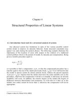
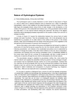
Rotating biological contactor
Rotating biological contactors (RBCs) combine suspended-growth and
attached-growth bioprocesses. In RBCs, a series of closely spaced circular
The shaft is located either just above or just below the water surface. This
location allows the surface of the disks to be exposed to both air and waste-
water while rotating. A typical disk is made of an inert material such as
polystyrene or polyvinyl chloride. A fixed-film biological growth attaches to
the disks and, when submerged, the organisms are exposed to food. In
rotation, the reactor carries the fixed film into the air, where it absorbs
oxygen. Excess dissolved oxygen mixes with the bulk liquid as the contactor
surface moves back through the wastewater (ASCE, 1977). As the thickness
of attached biomass on the disk increases, some of excess biomass is sheared
off the disk. This biomass is kept in suspension by the rotation of the disks.
Ultimately, the flow of wastewater carries the solids out of the reactor cham-
ber and into the clarifier.
Figure 4.3 Coupled contact aeration system.
Photo 4.1 Rotating biological contactor.
Chamber
Settling
Baffle
Baffle
Sludge
Return
EffluentInfluent
(from Primary Tank)
Maintenance Access
Aeration
Device
(clarifier)
disks are mounted on a common shaft and are slowly rotated (Photo 4.1).
© 2006 by Taylor & Francis Group, LLC
126 Advanced onsite wastewater systems technologies
Generally, about 35 to 45% of a disk's surface is submerged in a RBC
that is designed with the shaft just above the water surface. A system that
has the shaft submerged in the water produces about 70% to 90% submer-
gence (Crites and Tchobanoglous, 1998). A higher degree of organic removal
and nitrification may be obtained by arranging sets of disks (or other inert
media) in series, because each subsequent stage receives an influent with a
lower organic concentration than the previous stage. The tank construction
usually consists of reinforced concrete or steel and is enclosed to maintain
environmental controls and to confine any nuisance odors. RBCs can be
scaled down for single-family homes or scaled up to provide secondary
treatment at municipal wastewater treatment plants (Metcalf & Eddy, Inc.,
2003).
Sequencing batch reactor systems or periodic processes
In sequencing batch reactor (SBR) systems, flow equalization, aeration, clar-
ification, and biomass wasting processes are carried out sequentially in the
same tank (U.S. EPA, 1986, 1992). Because most SBRs require the system to
be closed to influent during the treatment cycles, two reactors operating in
parallel are required in order to maintain continuous flow. However, with
new inlet designs, single-tank reactors can be used to maintain continuous
flow. The SBR process can provide flow equalization and tends to modulate
the quantity and strength of wastewater inflow.
SBR process description
One cycle of SBR operation has five basic modes:
• Fill — Raw wastewater that has been through primary treatment is
added to the reactor. During this phase, aeration may or may not be
supplied to provide alternating periods of high and low dissolved
oxygen. This mode may occupy 25% of the total cycle time.
• React — Aeration is provided in an effort to obtain rapid biodegra-
dation of organic and nitrogenous compounds. This mode typically
consumes about 35% of the total cycle time.
• Settle — Aeration is shut off to allow the wastewater to become
anoxic (for denitrification) and to allow for quiescent conditions that
permit very effective liquid-solid separation. Clarification usually
takes about 20% of the overall cycle time.
• Draw (also called “decanting”)— Clarified supernatant is removed.
Decanting is accomplished using adjustable weirs, floating weirs, and
submersible pumps. Excess biosolids must periodically be removed.
Decanting generally takes about 15% of the total cycle time.
• Idle — Time is allowed for the first reactor to complete its full cycle,
and then switch the flow into the second reactor for parallel operation.
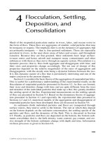
This cycle is illustrated in Figure 4.4.
© 2006 by Taylor & Francis Group, LLC
Chapter four: Aerobic treatment units 127
An important element in the SBR process is that a tank is never com-
pletely emptied; rather, a portion of settled solids are left to seed the next
cycle (Henry and Heinke, 1996). This allows the establishment of a popula-
tion of organisms uniquely suited to treating the wastewater. By subjecting
the organisms to periods of high and low oxygen levels, and to high and
low food availability, the population of organisms becomes very efficient at
treating the particular wastewater (Henry and Heinke, 1996).
Nitrogen removal in SBRs
During aeration, organic and ammonia nitrogen present in the wastewater
are converted to nitrate. When aeration is suspended and the remaining
dissolved oxygen is consumed, denitrifying bacteria strip the oxygen out of
the nitrate molecule, converting nitrate to nitrogen gas (denitrification).
While other ATUs can be designed to provide denitrification, the SBR
sequence can provide denitrification conditions without adding additional
unit processes.
Figure 4.4 Sequencing Batch Reactor (SBR) cycles.
Sequence One: Fill
Add Substrate
Aeration: Cycled On-Off
Percent of Cycle Time: Approximately 25%
Sequence Two: React
Biochemical Oxidation of Organic
Aeration: On-Off to promote Denitrification
Percent of Cycle Time: Approximately 35%
Sequence Three: Settle
Clarification of Suspended Solids & Biomass
Aeration: Off
Percent of Cycle Time: Approximately 20%
Sequence Four: Draw
Remove Clarified Effluent
Aeration: Off
Percent of Cycle Time: Approximately 15%
Sequence Five: Idle
Waste Sludge
Aeration: Cycled On-Off
Percent of Cycle Time: Approximately 5%
© 2006 by Taylor & Francis Group, LLC
128 Advanced onsite wastewater systems technologies
Typical applications of SBRs
With the development of reliable automatic control systems, SBR package
plants have become competitive with more traditional ATUs. The process is
flexible and efficient and can accommodate large fluctuations in hydraulic
and organic loads. The process is particularly applicable to small communi-
ties, because of easy installation, simple operation, lower maintenance, and
higher energy efficiency (U.S. EPA, 1992).
Other Process Considerations
Oxygen transfer
Large quantities of oxygen must be provided to maintain aerobic conditions.
If influent to the ATU has an ultimate BOD of 100 mg/L, then 100 mg of
dissolved oxygen per liter of influent must be provided to satisfy the oxygen
demand. The primary function of the aeration system is to transfer oxygen
to the liquid at such a rate that dissolved oxygen never becomes a limiting
factor. Oxygen is only slightly soluble in water. Natural aeration cannot meet
the demand of this high-rate unit process and, therefore, oxygen transfer
must be engineered into the treatment unit in order to maintain a minimum
residual of 1 mg of dissolved oxygen per liter of water.
The passage of oxygen from the gas phase (air) into the liquid (waste-
water) phase is absorption. The driving force of oxygen transfer is the con-
centration gradient between the atmosphere and the bulk liquid. This gra-
dient is created when there is a difference in the equilibrium concentration
in the two phases. Thus, the force required to obtain equilibrium drives the
transfer of atmospheric oxygen into the water. The saturated concentration
of dissolved oxygen changes with temperature, barometric pressure, and
salinity and with the concentration of water impurities. Designers of ATUs
must maximize the contact interface (surface area) between the gas and
liquid phases in order to maximize the opportunity for oxygen transfer. In
other words, systems must be designed so that the concentration gradient
between the gas-liquid interfaces is high and, therefore, the rate of transfer
will also be high.
Aeration units are evaluated on the mass of oxygen transferred per unit
of air introduced to the water. This is known as an efficiency rating. The goal
is to maximize the mass of oxygen transferred per unit of energy consumed
by the device. The most common method of maximizing energy efficiency
is to combine mixing with aeration. Turbulent mixing is required to maxi-
mize the opportunity for microbes to come in contact with both soluble
organic compounds and dissolved oxygen. If steady-state conditions can be
maintained, the rate of oxygen transfer is equal to the rate of consumption
by the microorganisms. Dissolved oxygen in the mixed liquor should be
maintained at 1 to 3 mg/L. For residential-strength wastewater, Metcalf &
Eddy, Inc. (2003) reports that 2 to 7 g/day of dissolved oxygen is needed for
each gram of MLVSS.
© 2006 by Taylor & Francis Group, LLC
Chapter four: Aerobic treatment units 129
For most ATUs, the actual oxygen mass transfer efficiency is proprietary
information. Manufacturers market specific ATU models based on organic
and hydraulic loading. For a given unit, the aeration device is rated to
provide sufficient dissolved oxygen for the given range of input oxygen
demands (organic loading).
Basically, manufacturers of ATUs utilize two types of aerators: diffused
air systems and mechanical aeration systems. Diffused air systems use sub-
merged devices (spargers) to inject air into the bulk liquid. As shown in
Figure 4.5, air injected below the surface has continuous contact with the
liquid as it rises to the surface. The smaller the bubble, the greater the oxygen
transfer rate. Additionally, bubbles formed deep within the chamber have
more hydrostatic pressure to drive the oxygen transfer and more time-of-con-
tact with the air-water interface. Another method of creating small bubbles
involves porous ceramic diffusers. The small, interconnected passageways
inside the ceramic matrix create a tremendous loss of air pressure and many
points of outflow. This combination produces streams of small bubbles over
the surface of the ceramic diffuser. A second method of injecting air is to
precisely drill orifices into pipes and plates. Many large-scale aerobic digest-
ers use jet aerators. Streams of air serve to transfer oxygen and to provide
vigorous mixing of basin contents.
A third type of diffused aerator is an aspirated mixer. As shown in Figure
4.6, a mixing-propeller attaches to a hollow shaft that vents to the atmo-
sphere. This propeller is located near the bottom of the aeration chamber.
As the shaft spins, a venturi effect creates a vacuum down the shaft and
injects air into the water. The mixing devices must balance the need for
Figure 4.5 Aeration in an ATU by air spargers.
Figure 4.6 Aspirated mixer for aeration of an ATU.
Chamber
Settling
Chamber
Aeration
Air Sparger
Baffle
Baffle
Sludge
Return
Effluent
Influent
Blower
(from Primary Tank)
Maintenance Access
Chamber
Settling
Baffle
Baffle
Sludge
Return
EffluentInfluent
(from Primary Tank)
Maintenance Access
Aeration&
Mixing
Chamber
Aspirated Mixer
Hollow Shaft
Motor
© 2006 by Taylor & Francis Group, LLC
130 Advanced onsite wastewater systems technologies
agitation while minimizing the shearing of floc. If shear is excessive, poor
settling conditions in the clarifier can result.
Several ATU manufacturers employ a cycled-aeration approach. Cycling
the aeration system provides some energy savings and promotes nitrogen
removal (temporary anoxic conditions). Care must be taken, however,
because this technique can produce a poor settling biomass due to gas
flotation and nonflocculating microbes.
ATU influent
Influent to an aerobic treatment chamber typically passes through primary
treatment, provided by either a septic tank or some other type of primary
tank. ATUs that can receive raw wastewater directly from a house and do
not require primary tanks are also available. When used, primary tanks can
provide separation of easily settleable and floatable solids before the influent
enters the ATU. A large portion of these solids are likely nondegradable or
slowly degradable. Manufacturers of ATUs provide guidance regarding the
required size of a primary tank for their aerobic treatment devices. Primary
tanks also provide an element of dilution that minimizes the effects of chem-
ical shocks on the microbial population in the ATUs. Medications, such as
antibiotics and chemotherapy drugs, are highly toxic to the microbial pop-
ulation. Most manufacturers list products that should not be added to the
wastewater stream. In some manufacturers’ literature, this list includes water
softener brine backwash.
Hydraulic and organic loading
The specifications of an ATU are based on both hydraulic and organic load-
ing. Hydraulic loading is the rate that water passes through the device; it
provides information about the length of time that wastewater will be
exposed to microbes. For example, if a basin has a volume of 1000 gal and
the wastewater flow is 500 gal per day (gpd), the hydraulic detention time
is 2 days. Organic loading refers to the food (incoming colloidal and soluble
BOD) as compared to the microbial population available to consume the
food (F/M ratio). Organic load is typically expressed in pounds per day.
Used in this way, load is the product of flow and concentration, as indicated
in Equation 4-6. If there is more food than microbes, the effluent quality will
be poor. If there are more microbes than food, then the effluent quality will
be high. As previously mentioned, the population of microbes is dynamic
in an ATU.
Load (Lb per day) = Flow (gpd) × concentration (mg/L) × 8.34 × 10
–6
(4.6)
If a system has been upset due to heavy laundry water loads that are
low in soluble BOD, the microbial population may be reduced because of a
© 2006 by Taylor & Francis Group, LLC
Chapter four: Aerobic treatment units 131
lack of food. Additionally, wash-out of microbes can occur if hydraulic
loading is greater than the designed outflow rate of the clarifier. When the
next heavy dose of organic material enters the tank, the microbial population
may be insufficient to complete the digestion of BOD during the hydraulic
detention period. This phenomenon has been observed in seasonal applica-
tions, such as baseball fields and state parks. Furthermore, if an ATU is
designed for a subdivision at ultimate build out, the F/M may not be ade-
quate when only a few homes have been built in the subdivision during the
early stages of development.
Flow equalization
ATUs are designed to work within a range of hydraulic and organic loads.
Variations in flow rates and constituent concentrations that are outside of
the design specifications seriously complicate the treatment process. Munic-
ipal plants have the advantage of serving large populations, which tend to
balance their daily organic and hydraulic loading rates. However, during
storm events, municipal plants must deal with tremendous inflow and infil-
tration problems. Municipal plants commonly use offline equalization basins
or bypass aerobic treatments in order to prevent wash-out of microbes.
Likewise, residential ATUs must be designed to handle days with high flows
and still be able to provide sufficient biochemical treatment to discharged
wastewater. Ideally, flow equalization would dampen the variations, so that
there would be a constant or near-constant flow rate into the ATU. Equal-
ization can be achieved with storage, float switches, pumps, and timers.
Generally, additional storage in the primary tank is the most cost-effective
method to accomplish flow equalization because tankage is usually the least
costly portion of the overall expenses (Bounds, 2003). Most ATUs are not
designed to provide flow equalization and, therefore, equalization must be
provided just prior to the ATU.
Nitrogen and phosphorus in wastewater
The presence of nitrogen in wastewater results from the degradation of
proteinaceous matter in feces and from urea, the chief constituent in urine.
Nitrogenous compounds undergo various biotransformations in response to
the presence or absence of dissolved oxygen. ATU influent, having just exited
from a septic tank or other primary treatment system, contains nitrogen in
organic or reduced-ammonium ion form. In the aerobic environment of an
ATU, most of the ammonium will be oxidized to nitrate (NO
3
), which is the
most highly oxidized form of nitrogen. While in the ATU, a fraction of
nitrogen may be removed by sedimentation, volatilization, and denitrifica-
tion. Unless process modifications are made to the ATU, no reliance on net
nitrogen removal can be expected. Nitrogen removal is highly dependent on
specific performance of individual ATUs to create denitrification conditions.
© 2006 by Taylor & Francis Group, LLC
132 Advanced onsite wastewater systems technologies
Because phosphorus is often a limiting nutrient in natural ecosystems,
eutrophication can occur when excess phosphorus is discharged to a surface
water body. In wastewater, phosphorus can be bound in organic compounds
or can be in soluble phosphate form (PO
4
). Typical phosphorus concentra-
tions in septic tank effluent range between 6 and 12 mg/L. Bacteria assimilate
a small portion of the orthophosphate during their growth process. Concep-
tually, this amount of phosphorous could be removed by sedimentation.
Because residential ATUs operate in the endogenous phase, very little sludge
wastage (and thus very little phosphorus removal) occurs. When a higher
degree of phosphorus removal is needed, a more advanced wastewater
treatment system, such as chemical precipitation or a wastewater treatment
plant designed for biological nutrient removal, would be required.
Operational issues
Start up
Start up involves the establishment of a sufficient population of microbes
within the ATU to digest the soluble organic and nitrogenous components
of influent. In most applications, a sufficient population of microbes enter
the ATU with the wastewater to start the process. If needed, one method of
inoculating the system is to add a few gallons of mixed liquor from an
operational ATU such as a municipal wastewater treatment plant. While the
biomass concentration is increasing, microbes tend to be dispersed and do
not form floc that will settle in the clarifier. Until the biomass becomes more
flocculated and can settle more readily, there is a greater potential for solids
carry over, especially with high hydraulic loads. If solids build up in the
clarifier, gas forms in the biosolids (as a result of anaerobic conditions within
the solids) and cause solids to rise to the surface and form a scum layer. The
quality of activated sludge offers a good measure of how well the process
is proceeding. Generally, good quality activated sludge has a golden-brown
color and an earthy smell if kept aerated. Microscopic examination also
reveals a relatively varied population, with a healthy population of rotifers
and other motile organisms.
Typical problems
Sludge bulking is a phenomenon that develops in the aeration tank when a
growth of filamentous bacteria (primarily Sphaerotilus) attaches to the floc
particles and impedes settling (Crites and Tchobanoglous, 1998). Such micro-
organisms can tolerate large changes in dissolved oxygen and nutrients, a
situation that frequently occurs in small ATUs. These conditions cause a
carryover of solids into the effluent. This phenomenon is particularly trou-
blesome to smaller plants that may have considerable fluctuation in organic
loading and lack of technical support.
© 2006 by Taylor & Francis Group, LLC
Chapter four: Aerobic treatment units 133
When excessive growth of Nocardia (a hydrophobic bacterium) occurs,
foaming and frothing on the liquid surface in the aeration chamber (and the
clarifier) may result. The problem is exacerbated by the fact that the baffles
in the clarifier trap the foam and foster more growth (Crites and Tchobano-
glous, 1998). Some ATU manufacturers provide froth spray pumps. The froth
spray reduces the surface tension of the water and breaks down the froth
(Ohio EPA, 2000).
Biomass (sludge) wastage
Although ATUs use the extended aeration process, endogenous degradation
cannot completely prevent accumulation of old biomass. Biomass and non-
biodegradable solids commonly accumulate in a low areas of ATUs and,
periodically, a maintenance provider must remove a portion of these solids.
During removal, it is important to leave some of the solids in the aerobic
chamber to serve as seed to repopulate the biological floc.
Performance certification
The National Sanitation Foundation (NSF International) and the American
National Standards Institute (ANSI) publish a standardized procedure for
independent evaluators to certify the performance and reliability of aeration
units. NSF/ANSI Standard 40-2000, "Residential Wastewater Treatment Sys-
tems," establishes minimum materials, design and construction, and perfor-
mance requirements for residential wastewater treatment systems having
single, defined discharge points and treatment capacities between 400 and
1500 gpd.
Mechanical evaluation
Design and construction requirements of the NSF/ANSI Standard ensure
that structural integrity is maintained when a system is subjected to earth
and hydrostatic pressures. An in situ visual evaluation of the structural
elements is performed during and after the performance testing period. The
system is tested to ensure that it is watertight (i.e., no infiltration of ground-
water or exfiltration of wastewater occurs). Water tightness is evaluated by
filling the tank with tap water to the level of the high-level alarm. This level
is then monitored for 24 hours.
All ATUs have moving parts. These parts operate in very corrosive
environments and therefore require periodic maintenance and replacement.
During the certification procedure, all mechanical components are evaluated
to determine the frequency of required maintenance and the ease by which
maintenance can be performed by a service provider. Inspections are con-
ducted to ensure that all electrical components are protected by safety
devices that meet or exceed ANSI/National Fire Protection Association
(NFPA) Standard 70. ATUs must have mechanisms or processes capable of
© 2006 by Taylor & Francis Group, LLC
134 Advanced onsite wastewater systems technologies
detecting failures of electrical and mechanical components that are critical
to the treatment processes and detecting high water conditions. These mech-
anisms must be capable of delivering visible and audible signals to notify
owners when electrical, mechanical, or hydraulic malfunctions occur.
All units must have ground-level access ports for visual inspection,
periodic cleaning, replacement of components, removal of residuals, and
sampling. Access to ports must be protected against unauthorized intrusion
via padlocks, covers requiring the use of special tools, or covers weighing a
minimum 65 Lb (29 kg).
Performance evaluation
NSF performance testing and evaluation of a specific type or model of
treatment system is conducted for 26 consecutive weeks, with 16 weeks
of design loading followed by 7.5 weeks of stress loading, and another
2.5 weeks of design loading. Design loading consists of operating 7 days
per week with a wastewater volume equivalent to the daily hydraulic
capacity of the unit. The 30-day average carbonaceous BOD
5
(CBOD
5
) and
total suspended solids (TSS) concentrations of wastewater entering the
system should range between 100 and 300 mg/L and 100 and 350 mg/L,
respectively. Stress loading is designed to simulate four nondesign con-
ditions: laundry day, working parents, power or equipment failure, and
vacation.
Performance testing and evaluation are conducted during 96 data days,
with no interruptions for routine service or maintenance. Unless otherwise
specified, all sample-collection and analysis methods must be in accordance
with the current edition of the American Public Health Association's Stan-
dard Methods for the Examination of Water and Wastewater. During periods
of design loading, daily composite effluent samples are collected and ana-
lyzed 5 days per week. During stress-loading conditions, influent and efflu-
ent 24-hr composite samples are collected on the day each stress condition
is initiated. Afterwards, samples are taken to monitor the recovery of the
treatment unit. Twenty-four hours after the completion of the wash-day,
working-parent, and vacation stresses, influent and effluent 24-hr composite
samples are collected for 6 consecutive days. Forty-eight hours after the
completion of the power/equipment failure stress, influent and effluent
24-hr composite samples are collected for 5 consecutive days.
Residential wastewater treatment systems are classified as either Class
I or Class II, according to the chemical, biological, and physical charac-
teristics of their effluents. A Class I certification indicates performance to
EPA Secondary Treatment Guidelines for three parameters: CBOD
5
, solids,
and pH (U.S. EPA, 1996). During the first calendar month of performance
testing and evaluation, a unit is allowed to exceed 1.4 times the effluent
limits for CBOD
5
and TSS sample concentrations without losing Class I
status. A system can be designated Class II if 10% (or less) of its effluent
CBOD
5
and TSS sample concentrations are greater than 60 mg/L and 100
© 2006 by Taylor & Francis Group, LLC
Chapter four: Aerobic treatment units 135
mg/L, respectively. Table 4.2 provides the criteria for Class I and Class II
performance standards.
As shown in Table 4.2, the performance bases of NSF/ANSI Standard
40 are organic carbon and suspended solids in the effluent. However, there
is increased interest in evaluating treatment units for their capacity to remove
nitrogen, phosphorus, and pathogens. Standard 40 provides procedures for
evaluation of the removal of these constituents. However, specific perfor-
mance of the removal of these constituents is not required in order to receive
certification (Converse, 2001). The primary function of saturated ATUs is the
digestion of soluble and colloidal organic compounds and removal of solids.
Additional unit processes are added to the treatment train to provide deni-
trification, phosphorus removal, and disinfection.
References
American Society of Civil Engineers. 1977. Wastewater Treatment Plant Design, Manual
of Practice No. 36. Lancaster Press, Lancaster, PA.
Benefield, L.D. and C.W. Randall. 1985 . Biological Process Design for Wastewater Treat-
ment. Ibis Publishing, Charlottesville, Virginia.
Bounds, T. 2003. Personal communication. Orenco Systems, Inc. May 24.
Converse, 2001. Aeration treatment of onsite domestic wastewater, aerobic units and
packed bed filters. Small Scale Waste Management Project, University of
Crites, R., and G. Tchobanoglous. Small and Decentralized Wastewater Management
Systems. Boston: WCB/McGraw-Hill Companies, Inc., 1998.
Davis, M.L. and D.A. Cornwell. 1991. Introduction to Environmental Engineering.
McGraw-Hill, New York.
Dinges, R. 1982. Natural Systems for Water Pollution Control. Van Nostrand Reinhold,
New York.
Table 4.2
NSF/ANSI Standard Number 40-2000 Performance Classifications
Class I
Parameter
30 day average shall not
exceed
7 day average shall not
exceed
CBOD
5
25 mg/L 40 mg/L
TSS 30 mg/L 45 mg/L
Color Individual samples shall be less than 15 NTU units
Threshold odor Nonoffensive
Oily film None visible other than air bubbles
Foam None
pH The individual effluent samples shall be between 6.0 and 9.0
Class II
Not more than 10% of the effluent BOD
5
values shall exceed 60 mg/L and not
more than 10% of the effluent TSS values shall exceed 100 mg/L.
Wisconsin, Madison, www.wisc.edu/sswmp Publication List.
© 2006 by Taylor & Francis Group, LLC
136 Advanced onsite wastewater systems technologies
Eikum, A. and T. Bennett. 1992. New Norwegian technology for treatment of small
flows. Proceedings of the Seventh Northwest On-site Wastewater Treatment
Short Course and Equipment Exhibition. University of Washington, Seattle,
WA .
Henry, J.G. and G.W. Heinke. 1996. Environmental Science and Engineering, Second
Edition. Prentice Hall, Upper Saddle River, N.J.
Lehninger, A.L. 1973. Bioenergetics, Second Edition. W.A. Benjamin, Inc. Menlo Park,
California.
Martin, E.J. and E.T. Martin. 1991. Technologies for Small Water and Wastewater Systems.
Van Nostrand Reinhold, New York.
Metcalf & Eddy, Inc. 2003. Wastewater Engineering: Treatment and Reuse, Fourth Edition.
McGraw-Hill, Boston.
Ohio Environmental Protection Agency. 2000. Guide for owners of package extended
aeration sewage treatment plants: Operation and maintenance. State of Ohio
EPA, Division of Surface Water.
Reynolds, T.D. 1982. Unit Operations and Processes in Environmental Engineering. PWS
Publishing Co., Boston.
U.S. Environmental Protection Agency. 1986. Summary Report: Sequencing Batch
Reactors. Office of Water, Washington, D.C., EPA 625886011.
U.S. Environmental Protection Agency. 1992. Summary Report: Small Community
Water and Wastewater Treatment. Office of Water, Washington, D.C., EPA/
625/R-92/010.
U.S. Environmental Protection Agency. 1996. Permit Writers' Manual. Office of Water,
Washington, D.C., EPA-833-B-96-003.
U.S. Environmental Protection Agency (2002). Decentralized Systems Technology
Fact Sheet — Aerobic Treatment. Office of Water, Washington, D.C., EPA
832-F-00-031.
U.S. Environmental Protection Agency. 2002. Onsite Wastewater Treatment Systems
Manual. Office of Water, Washington, D.C., EPA/625/R-00/008.