Wiley SolidWorks 2009 Bible Part 11 pot
Bạn đang xem bản rút gọn của tài liệu. Xem và tải ngay bản đầy đủ của tài liệu tại đây (2.56 MB, 80 trang )
781
Modeling Multi-bodies
26
FIGURE 26.21
Control the visibility of FeatureManager items
FIGURE 26.22
Using the Show Feature History option
The Insert into New Part feature and the Save Bodies feature seen in this menu are discussed in
Chapter 28.
You can expand the Display pane in parts, in order to show display information for bodies. In
Figure 26.23, the Display pane shows the colors assigned to the solid bodies, as well as the fact
that several surface bodies exist but are hidden.
782
Using Advanced Techniques
Part VI
FIGURE 26.23
The Display pane showing information about solid and surface bodies
The folders also make bodies easier to identify, especially when combined with the setting found at
Tools ➪ Options ➪ Display/Selection ➪ Dynamic Highlight From Graphics View. This setting
quickly turns the body outline red if you move the mouse over the body in the body folder.
Hide or show bodies
You can hide or show bodies in one of several ways. I have already described the method of using
the bodies folders to hide or show all of the bodies at once, but you can also right-click individual
bodies in the folders to hide or show from there as well. Remember that with the Context bars, you
have the option to use context bars with the right-mouse button menu or not, and also context
bars with left click selections. I include all context bar options in the right-mouse button menu
generically.
if you can see a body in the graphics area, then you can right-click the body and select Hide under
the Body heading. This works for both solids and surfaces. The Display Pane, shown to the right
of the FeatureManager in Figure 26.23, can also be used to hide or show bodies, change body
transparency and appearance, as well as change the display mode of bodies. Display Pane is a
handy tool for visualization options.
When you are hiding or showing bodies from the FeatureManager, and not using the bodies
folders, but rather using the features themselves, things get a little complicated. If you want to hide
or show a solid body, then you can use any feature that is a parent of the body to hide or show the
body. For example, you can use the Shell feature in the mouse model to hide or show all of the
bodies of which it is a parent.
Other facts that you need to know about bodies and their hide or show states are that the Hide or
Show feature is both configurable and dependent on the rollback state. As a result, if you hide a
body, and then roll back, it may appear again, and you will have to hide it. Then, if you roll
forward, the state changes again. Also, a body can be hidden in one configuration, and then when
you switch configurations, it remains hidden. This makes it rather frustrating to work with bodies.
To me, it would be nice if bodies had simple on/off toggles that were neither intelligent nor tricky.
783
Modeling Multi-bodies
26
CAUTION
CAUTION
Some features exclude bodies if the bodies are hidden when you edit the feature.
Be careful of this, and be sure to show all of the bodies that are used in a particular
function before you edit it. For example, if a body is hidden, and you create a new extrude that
touches the hidden body, then the new body does not merge with the hidden one even if the
Merge option is on. If the hidden body is then shown and you edit the second body, then the
bodies will merge upon the closing of the second body.
Deleting bodies
I have already mentioned that you can delete bodies using the Delete Bodies feature, and that this
feature sits in the tree at a specific point in the history of the part.
Delete Bodies does not affect file size or rebuild speed. In fact, I find it difficult to come up with
examples of when you should use it, other than the situation already mentioned with the Rib
feature, or if a throwaway body somehow remains in the part. Some people use this feature to
clean up the organization of the tree, which could be useful if there are many bodies in the part.
Other users insist on keeping the tree free of extraneous bodies, and so they immediately delete
bodies that have been used. To me, this technique replaces one kind of clutter with another, and
means that tools that should be available to you (solid or surface bodies) are not available unless
you reorder the Delete Body feature down the tree and/or roll back. In any case, this is really a
matter of personal working style and not of any great importance.
Renaming bodies
Notice that the bodies that you see in the folders have been named for the last feature that touched
a given body. That naming scheme is as good as any, except that it means that the body keeps
changing names. If you deliberately rename a body, it will retain the name through future changes.
You should follow the same rules of thumb for naming bodies as you do for naming features.
Tutorials: Working with Multi-bodies
This tutorial contains various short examples of multi-body techniques in order from easy to more
difficult.
Merging and local operations
This tutorial gives you some experience using the Merge Result option and using features on
individual bodies to demonstrate the local operations functionality of multi-body modeling. Try
these steps:
1. Start a new part, and sketch a rectangle centered on the origin on the Top plane.
Size is not important for this exercise.
2. Extrude the rectangle to roughly one-third of its smaller dimension.
3. Open a second sketch on the Top plane. Hide the first solid body by right-clicking it in
either the FeatureManager or the graphics window.
784
Using Advanced Techniques
Part VI
4. Show the sketch for the first feature, and draw a second rectangle on the far side of
the rectangle from the Origin. Make sure that the second rectangle gets two coincident
relations to the first sketch, at two corners so that the rectangles are the same width.
When the sketch is complete, hide the sketch that was shown.
5. Extrude the second rectangle to about two-thirds of the depth of the first rectangle.
NOTE
NOTE
Notice that the Merge option was not changed from the default setting of On for
the second extrude, but because the first extrude was hidden, the second extrude
did not merge with it. Be careful of subsequent edits to either of the features if the first body is
shown, because this may cause the bodies to merge unexpectedly. In this tutorial, the bodies are
later merged intentionally. Ideally, what you should do is deselect the Merge option of the
second extrude.
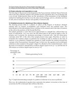
6. Shell out the second extrusion by removing two adjacent sides, as shown in Figure
26.24. One of the sides is the top and the other is the shared side with the hidden body.
The body that should be hidden at this point is shown as transparent in the image for
reference only. The body was made transparent to make it easier to select the face of the
second body.
FIGURE 26.24
Shelling two sides of a block
7. Show the first body either from the Solid Bodies folder at the top of the tree or from
the right-mouse button menu of the first solid feature in the tree.
8. Shell the bottom side of the first body, so that the cavities in the two bodies are on
opposite sides.
9. Combine the two bodies using the Combine tool found at Insert ➪ Features ➪
Combine. This feature is also available via right-mouse button in the solid body folder.
Select the Add option and select the two bodies. Click OK to finish the feature. Figure
26.25 shows the finished part.
785
Modeling Multi-bodies
26
FIGURE 26.25
The finished part
Splitting and patterning bodies
This tutorial guides you through the steps to delete a pattern of features from an imported body,
separate one of the features, and then pattern it with a different number of features. This intro-
duces some simple surface functions, in preparation for Chapter 27. Follow these steps:
1. Open the Parasolid file from the CD-ROM called Chapter 26 – Bonita
Tutorial.x_t.
2. Using the Selection Filter set to filter Face selection (the default hotkey for this is
X), select all of the faces of the leg. You can use window selection techniques to avoid
clicking each face.
3. Click the Delete Face button on the Surfaces toolbar, or access the command
through the menus at Insert ➪ Face ➪ Delete. Make sure that the Delete and Patch
option is selected. The selected faces and the Delete Face PropertyManager should look
like Figure 26.26. Click OK to accept the feature.
4. Repeat the process for a second leg, leaving the third leg to be separated from the
rest of the part and patterned.
5. After the two legs have been removed, click the outer main spherical surface, and
then from the menus, select Insert ➪ Surface ➪ Offset. Set the offset distance to zero.
Notice that a Surface Bodies folder is now added to the tree, near the top.
TIP
TIP
A zero distance offset surface is frequently used to copy faces.
6. Hide the solid body. You can do this from the Solid Bodies folder, from the
FeatureManager, or from the graphics window.
786
Using Advanced Techniques
Part VI
FIGURE 26.26
The Delete Face PropertyManager
7. Hiding the solid leaves the offset surface, and there should be three holes in it.
Select one of the edges of the hole indicated in Figure 26.27 and press the Delete key.
The Choose Option dialog box appears. Select the Delete Hole option rather than the
Delete Feature option. The Delete Hole operation becomes a history-based feature in the
model tree. Before moving on to the next step, remember that you may need to turn off
the Selection Filter for faces.
FIGURE 26.27
Using the Delete Hole option
NOTE
NOTE
Delete Hole is really a surface feature called Untrim. Untrim is discussed more in
Chapter 27, but you can use it to restore original boundaries to a surface.
8. Once you delete the hole from the surface body, change the color of the surface
body the same way you changed the colors of parts, faces, and features.
787
Modeling Multi-bodies
26
9. Click the surface body in the Surface Bodies folder and either press the Delete key,
or select Delete Body from the right-mouse button menu. Then click OK to accept
the feature. This places a Delete Body feature in the tree. It keeps the body from
getting in the way when it is not needed. This is not a necessary step, but many people
choose to use it.
TIP
TIP
If you delete a body in this way and then need it later down the tree, you can
delete, suppress, or reorder the Delete Body feature later in the tree.
10. Now show the solid body. You will notice the color of the surface conflicting with the
color of the solid. This mottled appearance is due to the small approximations made by
the rendering and display algorithms.
11. Initiate the Split feature through the menus at Insert ➪ Features ➪ Split, or on the
Features toolbar. Use the surface body to split the solid body. Click the Cut Part button,
and select the check boxes in front of both bodies in the list. Click OK to accept the
feature. Notice now that the Solid Bodies folder indicates that there are two solid bodies.
12. From the View menu, turn on the display of Temporary Axes. Initiate a Circular
Pattern feature, selecting the temporary axis as the axis, and the split-off leg in the Bodies
to Pattern selection box. Set it to four instances, as shown in Figure 26.28.
FIGURE 26.28
Patterning a body
13. Use the Combine feature to add together all five bodies. You can access this feature
through the menus at Insert ➪ Features ➪ Combine.
788
Using Advanced Techniques
Part VI
Summary
Beginning to understand how to work with multiple bodies in SolidWorks opens a gateway to a
new world of design possibilities. However, like anything else, not everything is perfect. Like
in-context design, multi-body modeling is definitely something that you have to go into with your
eyes open. You will experience difficulties when using this technique, but you will also find new
possibilities that were not available with other techniques. The key to success with multi-bodies
techniques is discipline and circumspection.
When using a model with the multi-body approach, make sure that you can identify a reason for
doing it this way rather than using a more conventional approach. Also keep in mind the list of
applications or uses for multi-body modeling mentioned in this chapter.
789
W
ith Surface modeling you build a shape face by face. Faces made
by surface features can be knit together to enclose a volume,
which can become a solid. With solid modeling, you build all
the faces to make the volume at the same time. In fact, solid modeling is
really just highly automated surface modeling. Obviously there is more detail
to it than that, but that definition will get you started.
You can drive a car without knowing how the engine works, but you cannot
get the most power possible out of the car by only pressing harder on the gas
pedal; you have to get under the hood and make adjustments. In a way, that
is what working with surfaces is really all about – getting under the hood
and tinkering with the underlying functionality.
The goal of most surface modeling is to finish with a solid. Some surface fea-
tures make faces that will become faces of the solid, and some surface fea-
tures only act as reference geometry. Surface modeling is inherently
multi-body modeling, because most surface features do not merge bodies
automatically.
Why Do You Need Surfaces?
In the end, you may never really need surfaces. It is possible to perform
workarounds using solids to do most of the things that most users need to
do. However, many of these workarounds are inefficient, cumbersome, and
raise as many difficulties as they solve. Although you may not view some of
the typical things you now do as inefficient and cumbersome, once you see
the alternatives, you may change your mind. The goal for this chapter is to
introduce surfacing functions to people who do not typically use surfaces,
IN THIS CHAPTER
Why do you need surfaces?
Understanding surfacing
terminology
What surface tools are
available?
Using surfacing techniques
Tutorial: Working with
surfaces
Working with Surfaces
790
Using Advanced Techniques
Part VI
and to people who do everyday modeling. I am not trying to show how surfaces are used in the
context of creating complex shapes, although you can use the same techniques, regardless of the
complexity of the shape.
The word surfacing has often been used (and confused) synonymously with the creation of com-
plex shapes. Not all surface work is done to create complex shapes, and many complex shapes can
be made directly from solids. Many users think that because they do not make complex shapes,
they never need to use surface features. This chapter shows mainly examples that are not complex
shapes, in situations where surfaces make it easier, more efficient, or simply possible to do the nec-
essary tasks.
While some of the uses of surfaces may not be immediately obvious, by the end of this chapter,
you should have enough information and applications that you can start experimenting to increase
your confidence.
Understanding Surfacing Terminology
When dealing with surfaces, you may hear different terminology than the terminology typically
used with solid modeling. It is important to understand the terminology, which makes the tech-
niques easier to understand. This special terminology also often exists for surfaces because of
important conceptual differences between how solids and surfaces are handled.
These terms are fairly universal among all surfacing software. The underlying surface and solid
construction concepts are generally uniform between the major software packages. What varies
from software to software is how the user interacts with the geometry through the software inter-
face. You may never see some of these terms in the SolidWorks menus, Help files, training books,
or elsewhere, but it becomes obvious as you use the software that the concepts are relevant.
Knit
Knit is analogous to the solid feature Combine in that it joins multiple surface bodies into a single
surface body. Unlike Combine, Knit does not perform the subtract or intersect Boolean operations.
It also has an option to create a solid if the resulting surface body meets the requirements (a fully
enclosed volume without gaps or overlaps). However, unlike the solid bodies in Combine, which
may overlap volumetrically, surface bodies must intersect edge to edge, more like sketch entities.
Knit is also sometimes used in the same way that the zero-distance offset is used, to copy a set of
solid faces to become a new surface body.
One nice option that enables you to quickly see where the boundaries of a surface body lie is
found at Tools ➪ Options ➪ Display/Selection ➪ Show Open Edges Of Surfaces In Different Color.
By default, this color is a medium blue, and you can change it at Tools ➪ Options ➪ Colors ➪
Surfaces ➪ Open Edges.
791
Working with Surfaces
27
Trim
The Trim function in SolidWorks is analogous to the solid Cut. Trim simply creates an additional
boundary for the surface. The underlying surface is defined by a two-dimensional mesh, and for
this reason, it is usually four-sided, but may be other shapes. When the underlying surface is
trimmed, the software still remembers the underlying shape, but combines it with the new bound-
ary, which is typically how face shapes (especially non-four-sided shapes) are created.
Untrim
Untrim is predictably the opposite of Trim. All it does is remove the boundary from a surface. It
can remove the boundary selectively (one edge at a time, interior edges only, and so on) or remove
all the edges at once. Untrim even works on imported geometry, as described in the tutorial in
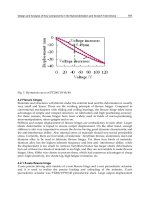
Chapter 26. Figure 27.1 shows how Untrim works.
FIGURE 27.1
Untrimming a surface
Untrim works on native and imported geometry. It is not truly like feature history in imported
geometry, but it does help to uncover the underlying original shape of the face.
Hybrid modeling
Modeling software has long divided itself along Solid/Surface lines with products such as Rhino
(strictly surface modeling) and early versions of SolidWorks (strictly solid modeling). However, in
the last several years, modelers are increasingly enabling both methods and allowing them to inter-
act. This hybrid modeling is a combination of solid and surface modeling. These days, it is much
more common to mix methods than it was even five years ago. Surface modeling is slow because
you model each face individually, and then manually trim and knit. Cutting a hole in a surface
model is much more involved than cutting a hole in a solid. Solid modeling is faster because it is
essentially highly automated surface modeling; however, as any software user knows, automation
almost always comes at the expense of flexibility, and this situation is no different. Surface model-
ing puts the compromised power back into your hands.
Solid modeling tends to limit you to a type of parts with square ends or a flat bottom because sol-
ids are creating all sides of an object at once. For example, think about an extrusion: regardless of
792
Using Advanced Techniques
Part VI
the shape of the rest of the feature, you have two flat ends. Even lofts and sweeps typically end up
with one or two flat ends because the section sketches are often planar. Surfaces enable you to cre-
ate one side at a time. Another way of looking at it is that using surfaces requires you to create one
side at a time.
You will find times when, even with prismatic modeling, surfacing functions are extremely useful,
if not completely indispensable. I do not propose that you dive into pure surface modeling just to
benefit from a few of the advantages, but I do recommend that you consider using surface tech-
niques to help define your solids. This hybrid approach is sensible and opens up a whole new
world of capabilities. I have heard people say after taking a SolidWorks surfacing class that they
would never look at the software in the same way again.
NURBS
NURBS stands for Non Uniform Rational B Spline. NURBS is the technology that most modern
mechanical design modelers use to create face geometry. NURBS surfaces are defined by curves in
perpendicular directions, referred to as U and V directions, which form a mesh. The fact that perpen-
dicular directions are used means that the surfaces have a tendency to be four-sided. Of course
exceptions exist, such as three-sided or even two-sided patches. Geometry of this kind is referred to
as degenerate, because one or more of the sides has been reduced to zero length. Degenerate geometry
is often, but not always, the source of geometrical errors in SolidWorks and other CAD packages.
Figure 27.2 shows some surfaces with the mesh displayed on them. You can create the mesh with
the Face Curves sketch tool.
FIGURE 27.2
Meshes created with the Face Curves sketch tool
Degenerate point
793
Working with Surfaces
27
An example of a competitive system to NURBS surface modeling is point mesh data. This comes from
systems such as 3DSMax, which create a set of points that are joined together in triangular facets, and
can be represented in SolidWorks as an STL (stereolithography) or VRML (virtual reality markup lan-
guage) file. When displayed in SolidWorks, this data looks very facetted or tessellated into small, flat
triangles, but when viewed in software that is meant to work with these kinds of meshes, it looks
smooth. Many advantages come with this type of data, especially when it comes to applying colors
and motion. However, the main disadvantage is that the geometrical accuracy is not very good. Point
mesh data is typically used by 3D graphic artists, animators, and game developers.
By using a SolidWorks add-in such as ScanTo3D, it is possible to take point mesh data and create a
NURBS mesh over it. This feature is not a push-button solution, but it offers capabilities where
none previously existed. ScanTo3D is beyond the scope of this book, but you should find it useful
if you are interested enough to read about NURBS and point meshes.
Developable surface
Developable surfaces are surfaces that can be flattened without stretching the material. They are
also surfaces that you can extend easily in one or both directions. These include planar, cylindrical,
and conical shapes. It is not a coincidence that these are the types of shapes that can be flattened
by the Sheet Metal tools.
Ruled surface
Developable surfaces are a special type of a broader range of surface called ruled surfaces.
SolidWorks has a special tool for the creation of ruled surfaces that is described in detail in the
next section. Ruled surfaces are defined as surfaces on which a straight line can be drawn at every
point. A corollary to this is that ruled surfaces may have curvature in only one direction. Ruled
surfaces are far less limited than developable surfaces, but are not as easily flattened.
Gaussian curvature
Gaussian curvature is not referred to directly in SolidWorks software, but you may hear the term
used in more general CAD or engineering discussions. It can be defined simply as curvature in two
directions. As a result, a sphere would have Gaussian curvature, but a cylinder would not.
What Surface Tools Are Available?
Surface feature equivalents are available for most solid features such as extrude, revolve, sweep,
loft, fillet, and so on. Some solid features do not have an equivalent, such as the Hole Wizard,
shell, and others. Several surface functions do not have solid equivalents, such as trim, Untrim,
Extend, Thicken, Offset, Radiate, Ruled, and Fill.
794
Using Advanced Techniques
Part VI
This is not a comprehensive guide to complex shape modeling, but it should serve as an introduc-
tion to each feature type and some of the details about how it operates.
Extruded Surface
The Extruded Surface works exactly like an extruded solid, except that the ends of the surface are
not capped. It includes all the same end conditions, draft, contour selection, sketch rules, and so
on that you are already familiar with. Figure 27.3 shows the PropertyManager for Extruded
Surface.
FIGURE 27.3
The Extruded Surface PropertyManager
You can also create extruded surfaces from open sketches, and, in fact, that is probably a more
common situation than creating a surface with a closed sketch.
When two non-parallel sketch lines are joined end to end, the result of extruding the sketch is a
single surface body that is made of two faces with a hard edge between them. If the sketch lines
were disjoint, then the extrude would result in disjoint surface bodies. If the sketch lines were
again made end to end, but done in separate sketches, then the resulting surface bodies would be
separate bodies; the second body would not be automatically knit to the first one as happens with
solid features. This is an important quality of surfaces to keep in mind. If you create surfaces in dif-
ferent features and want them knitted into a single body, then you will have to do that manually.
795
Working with Surfaces
27
Revolved Surface
The Revolved Surface functions like its solid counterpart, right down to the rules for how it han-
dles entities that are touching the axis of revolution; nothing can cross the axis. A single sketch
entity is allowed to touch it at a single point, but multiple sketch entities cannot touch it at the
same point.
Swept Surface
Swept surfaces work much like their solid counterpart, and the sketch rules and available entities
are the same. The main difference here is going to be that swept surfaces usually use an open con-
tour for the profile, while swept solids use closed contours.
Lofted Surface
The main difference between lofted surfaces and lofted solids is that the surfaces can use edges and
curve features to loft, rather than simply sketches and faces.
Boundary Surface
The Boundary Surface was created as a higher quality replacement for the Loft feature, but certain
limitations mean that Loft has not been removed from the feature list. Boundary surface most
resembles a loft, but has elements of the fill surface, and at times can also function like a sweep. It
requires you to select edges or sketch elements in two different directions, directly relating to the
NURBS scheme I discussed earlier in this chapter. This feature can work with only one set of edges
selected.
If several edge or sketch segments combine to form one side of a direction, then you must use the
SelectionManager to form the edge segments into a group. SelectionManager enables you to select
portions of a single sketch or to combine elements such as sketch, edge, and curve into a single
selection for use as a profile or guide curve for Boundary or Loft features.
The interface for the Boundary Surface is shown in Figure 27.4.
The types of models where you end up using the Boundary Surface are highly curvy models that
are modeled mainly with surface features, and require a four-sided patch.
The main advantage of Boundary Surface over Loft is that Boundary Surface can apply a Curvature
boundary condition all the way around, while Loft cannot apply curvature on the guide curves. Fill
surfaces also can apply a Curvature boundary condition all the way around.
Boundary Surface can be a rather nuanced feature, but when working on the type of model that
suits it well, I default to Boundary surfaces when possible. Boundary solid features are now also
available, and I expect these will also take a little bit of a learning curve to understand where they
are best applied.
796
Using Advanced Techniques
Part VI
FIGURE 27.4
The Boundary Surface PropertyManager
For a more detailed look at the primary shape creation tools (sweep, loft, boundary, and fill) and
surface modeling in general, please refer to the SolidWorks Surfacing and Complex Shape Modeling
Bible (Wiley, 2008).
Offset Surface
The Offset Surface has no solid feature counterpart, but it does in 3D what the Offset Sketch func-
tion does in 2D; it may also fail for the same reasons. For example, if you offset a .25-inch radius
arc by .3 inches to the inside, it fails because it cannot be offset up to or past a zero radius. The
same is true of offsetting surfaces. Complex surfaces do not have a constant curvature, but are
more like a spline in having a constantly changing curvature. If the offset is going in the direction
of decreasing radius, and is more than the minimum radius on the face or faces being offset, then
the Offset Surface feature will fail.
One of the ways to troubleshoot a failing Offset Surface is to use the Check tool to check for mini-
mum radius. Remember that minimum radius is only a problem if the curvature is in the same
direction as the offset. If a small radius will increase when it is offset, then that small radius is not
the problem. The problem comes from the other direction where you are offsetting to the inside of
a small radius.
797
Working with Surfaces
27
Unlike the Sketch Offset function — and as was shown in Chapter 26 — you can offset surfaces by
a zero distance. This is usually done to copy either solid or surface faces to make a new surface
body. Zero-distance offset and Knit are sometimes used interchangeably, although Knit causes a
problem if you are selecting a surface body that is composed of a single face. Knit assumes that you
are trying to knit one body to another, and so, by default, it selects the body, and then fails with
the message that you cannot knit a body to itself. Because Knit has this limitation, and Offset does
not, I prefer the Offset tool when copying faces to make a new surface body. You may also notice
that when you enter a zero for the offset distance, the Offset PropertyManager name changes auto-
matically to Copy Surface.
Knit does have two functions that Sketch Offset does not. One of these is the option to create a
solid from the knit body if it forms a closed body. The second option is somewhat more obscure,
offering the ability to select all faces on one side of a Radiate surface. I discuss this option in more
depth later in this chapter in the Knit Surface section.
When talking about copying surface bodies, you must also consider the Move/Copy Bodies feature,
which is described in Chapter 26. When simply copying a body without also moving it, this fea-
ture issues a warning that asks whether you really intend to copy the body without moving it. This
is an annoying and pointless message. Also, the Move/Copy Bodies feature does not enable you to
copy only a part of a body (selected faces) or to merge multiple bodies into one like the Knit and
Offset Surface features.
All things considered, I recommend using the zero-distance Surface Offset feature to copy bodies or
parts of bodies unless your goal is to immediately make a solid out of it (in which case you should
use the Knit feature) or when using a Radiated surface (typically in a mold-building application).
Radiate Surface
The Radiate Surface is not one of the more commonly used surface features. It has been largely
superseded by the Ruled Surface. This is because Ruled Surface does the same sort of thing that
Radiate Surface does, as well as a lot more, and is also more reliable. Radiate works from an edge
selection, a reference plane, and a distance. The newly created surface is perpendicular to the
selected edge, parallel to the selected plane, and the set distance wide. It is probably most com-
monly used in creating molds or other net shape tooling such as dies for stamping and forging,
blanks for thermoforming, and so on.
Figure 27.5 shows the PropertyManager and selection for creating a Radiate Surface.
TIP
TIP
The Radiate Surface feature does not give you a preview of the finished surface,
only the small arrows that indicate the direction in which the surface will radiate. At
times, you may need to switch the arrows to the other side, which you can do by using the arrow
button next to the plane selection.
CAUTION
CAUTION
When creating a Radiate Surface, the use of a loop in the edge selection always results
in an incorrect result, because the feature only uses the initial edge that was selected
for the loop. As long as individual edges are listed in the selection box, you should be okay.
798
Using Advanced Techniques
Part VI
FIGURE 27.5
The Radiate Surface PropertyManager
The one application where the Radiate Surface has a very interesting usage is when you combine it
with the Knit function, as mentioned earlier. Figure 27.6 shows a part surrounded by a Radiate
Surface in which the Knit feature is being used to select all the faces to one side of the radiated sur-
face. The second smaller selection box in the PropertyManager that contains Face<1> is called a
seed face and causes the Knit to automatically select all the faces on the same side of the model as
the selected seed face. The requirement here is that the Radiate goes completely around the model
and separates the faces into faces on one side of the Radiate and faces on the other side of the
Radiate. The use of the Radiate with the Seed Face selection is extremely useful for mold creation.
FIGURE 27.6
Using Radiate Surface with Knit
Radiated surface selected
Seed face selection
799
Working with Surfaces
27
Knit Surface
The Knit Surface functionality has been discussed in the terminology section and also in the
Radiate Surface section.
The one function that remains is the Try to form solid option. If the knit operation results in a
watertight volume, this option turns the volume into a solid. You can also make a solid from a sur-
face using two other functions. The Fill Surface has an option to merge the fill with a solid or to
knit it into a surface body; if the knit surface body is closed, then it gives you the option to make it
a solid. This is very nice, complete interface design, with options that save you many steps. The Fill
Surface feature is described in more detail later in this chapter.
The other function that also creates a solid from a surface is the Thicken feature. If a surface body
that encloses a volume is selected, then an option Create solid from enclosed volume appears on
the Thicken PropertyManager, as shown in Figure 27.7. You can access the Thicken feature from
the menus at Insert ➪ Boss/Base ➪ Thicken.
FIGURE 27.7
The Thicken PropertyManager
Planar Surface
Planar surfaces can be created quickly and are useful in many situations, not just for surfacing
work. Because they are by definition planar, you can use them to sketch on and for other purposes
that you may use a plane for, such as mirroring. Further, you can create a planar surface in a way
that many users have long wanted to use for creating a plane, by selecting two co-planar edges or
sketch lines.
However, more commonly, planar surfaces are created from a closed sketch such as a rectangle.
You can create multiple planar surfaces at once, and the surfaces do not need to all be on the same
plane or even parallel. This is commonly done to close up holes in a surface model, such as at the
bottom of cylindrical bosses on a plastic part, using a planar circular edge. A good example of this
is the bike frame part in the material for Chapter 27 on the CD-ROM, named
Chapter 27 –
bike frame.SLDPRT.
800
Using Advanced Techniques
Part VI
Remember that a planar surface was used in Chapter 26 with the Split feature to split the leg off of
an imported part. This was more effective than a sketch or a plane because the split was limited to
the bounds of the planar surface, not infinite like the sketch or the plane.
The planar surface does not knit itself into the rest of the surface bodies around it automatically;
you have to use the Knit feature to do this.
Extend Surface
The Extend Surface feature functions much in the same way that the Extend function works in
sketches. Figure 27.8 shows the PropertyManager interface and an example of the feature at work.
FIGURE 27.8
The Extend Surface PropertyManager
The only item here that requires explanation is the Extension Type panel. The Same surface option
means that the extended surface will simply be extrapolated in the selected direction. A planar sur-
face is the easiest to extend because it can go on indefinitely without running into problems. A
cylindrical surface can only be extended until it runs into itself. Complex lofted or swept surfaces
are often difficult to extend. Extrapolating a complex surface is not easy to do and often results in
self-intersecting faces, which cause the feature to fail.
When the Same Surface setting works, it creates a nice result because it does not create an edge
where the extension begins; it smoothly extends the existing face.
The Linear option is more reliable than the Same Surface option because it starts tangent to the
existing surface and keeps going in that direction, working much like a Ruled surface, which is
covered later in this chapter. It does not rely on extending the existing surface. This option creates
an edge at the starting point of the new geometry.
801
Working with Surfaces
27
Trim Surface
The Trim Surface feature is described briefly earlier in this chapter, but it warrants a more com-
plete description here. Surfaces can be trimmed by three different types of entities:
Sketches
Planes
Other surfaces
When you use surface bodies to trim one another, you must select one of two options: Standard or
Mutual Trim. The Standard option causes one surface to act as the Trim tool and the other surface
to be trimmed by the Trim tool. When you select the Mutual Trim option, both surfaces act as the
Trim tool, and both surfaces are trimmed.
For an example of trimmed surfaces, open the mouse example from Chapter 26 and step through
the tree. This shows examples of a couple of types of trimmed surfaces, as well as extended sur-
faces and others.
Many people overlook the ability to trim a surface with a plane, which can be very handy some-
times. Planes are infinite, which means you have less to worry about when it comes to changes that
affect features rebuilding correctly.
Finally, trimming with 2D sketches is well known, but trimming with 3D sketches is less known.
There is a 3D sketch tool called Spline on Surface that enables you to draw a spline directly on any
surface body. An option exists in the Trim Surface PropertyManager to trim a surface with this type
of sketch. This is very useful in many situations if you can remember that it is available.
Fill Surface
The Fill Surface is one of my favorite tools in SolidWorks. I often refer to it as the “magic wand”
because it is sometimes amazing what it can do. It is alternately referred to by the SolidWorks
interface and documentation as either Fill or Filled, depending on where the reference is made.
You will find it listed as both in the SolidWorks interface.
The Fill Surface is intended to fill in gaps in surface bodies. It can do this either smoothly or by
leaving sharp corners. You can use constraint curves to drive the shape of the fill between the exist-
ing boundaries. It can even knit a surface body together into a solid, all in one step. Beyond this,
you can use the Fill Surface directly on solid models and integrate it directly into the solid auto-
matically (much like the Replace Face function which is described later in this chapter).
Several rather complex examples of the Fill Surface are found in the bike frame example that was
originally shown in Chapter 12. One of these fills is shown in Figure 27.9.
802
Using Advanced Techniques
Part VI
FIGURE 27.9
The Fill Surface PropertyManager and the results of applying it
The first thing you should notice about the Fill Surface is that it is creating an oversized, four-sided
patch and trimming it to fit into the available space. This is one of the reasons why I consider this
to be such a magical tool. The four-sided patch I referred to earlier in the section on NURBS is
shown very clearly in this feature preview. Also, the trimmed surface concept is illustrated nicely
by this feature. Not surprising, if you Untrim the fill surface, then you return to the surface that is
previewed here. In this one function, SolidWorks gives you some useful insight about what is
going on behind the scenes.
When using the Fill Surface, it is best to have a patch completely bounded by other surfaces, as
shown in Figure 27.9. Fill Surface can work with a boundary that is not enclosed, but it works bet-
ter with a closed boundary.
You can set boundary conditions as Contact, Tangent, or Curvature. Contact simply means that the
faces touch at an edge. Tangent means that the slopes of the faces on either side of the edge match
at all points along the edge. Curvature means curvature continuous (or C2), where the fill surface
matches not only tangency, but also the curvature of the face on the other side of the boundary
edge. This results in a smoother transition than a transition that is simply tangent.
When you select the Optimize Surface option, SolidWorks tries to fit the four-sided patch into the
boundary. Notice that on this part, even though the Optimize Surface option is on, it is clearly
being ignored because the boundary is a six-sided gap, and cannot be patched smoothly with a
803
Working with Surfaces
27
four-sided patch. It is not necessarily an improvement to make a fill surface optimized, even when
it works.
Constraint curves can influence the shape of the fill surface. An example of this is shown in Figure
27.10. The construction splines shown on the faces of the part were created by the Intersection
Curve tool and enabled the spline used for the constraint curve to be made tangent to the surface.
FIGURE 27.10
The Fill Surface feature with constraint curves
MidSurface
The MidSurface feature is not used very often. It was probably originally intended to be used in
conjunction with analysis tools to create plate elements for thin walled structures. It works on par-
allel faces of a solid, creating a surface midway between the faces. If the faces have opposing draft
(such that a wall is wider at the bottom than at the top), then the MidSurface will not work. It
works on linear walls and cylindrical walls, but not on elliptical or spline-based shapes. The
PropertyManager for the Mid-surface is shown in Figure 27.11.
Similar to the Planar Surface, you can also use the Mid-surface to create a surface that can be used
like a plane. No plane type can create a symmetrical plane, but using a Mid-Surface, you can create
a symmetrical planar surface between parallel walls.
804
Using Advanced Techniques
Part VI
FIGURE 27.11
The Mid-surface PropertyManager
Replace Face
The Replace Face feature does not create new surface geometry, but it does integrate existing sur-
face geometry into the solid. It replaces selected faces of a solid or surface body with a selected sur-
face body. Replace Face is one of the few tools that can add and remove material at the same time
with a single feature.
If you were to manually perform the functions that are done by Replace Face, then you would start
by deleting several faces of the solid, then extending faces, and then trimming surface bodies, and
finish by knitting all the trimmed and extended faces back into a single solid body.
This is a very powerful and useful tool, although it is sometimes difficult to tell which situations it
will work in. Figure 27.12 shows a part before and after a Replace Face feature has been added.
The surface used to replace the flat face of the solid has been turned transparent. The first selection
box is for the original face or faces, and the second selection box is for the surface body with the
new faces. The tool tips for each of the boxes are Target Faces For Replacement and Replacement
Surface(s), which seem a little ambiguous. I like to think of them as Old (top) and New (bottom).
Untrim Surface
The Untrim Surface is discussed in the terminology section of this chapter. You can use it either
selectively on edges or on the entire surface body.