Safety at Work 6 E Part 14 potx
Bạn đang xem bản rút gọn của tài liệu. Xem và tải ngay bản đầy đủ của tài liệu tại đây (352.66 KB, 60 trang )
Safe use of machinery 755
(b) along a fixed course even where it does not move along
guides which are rigid (for example, a scissor lift),
and inclined at an angle of more than 15 degrees to the
horizontal and intended for the transport of:
– persons
– persons and goods
– goods alone if the car is accessible, that is to say, a person
may enter it without difficulty, and fitted with controls
situated inside the car or within reach of a person
inside.’
4.3.5.2 Construction of lifting equipment
4.3.5.2.1 Cranes
Cranes and their accessories are work equipment and as such must be
designed and manufactured to conform with SMSR with supporting
documentation as evidence of conformity. In addition, before they are
put into service they must be subjected to the tests summarised in Table
4.3.1. The supplier should issue a Test Certificate on completion of the
test.
4.3.5.2.2 Lifts
The manufacture of lifts follows the same procedural requirements as
other work equipment but with the added requirements contained in
the Lifts Regulations (LR) which recognises the value of quality
assurance schemes and also the fact that many of the components may
be supplied by specialist manufacturers. Similar obligations are placed
on both the lift manufacturer (reg. 8) and the component manufacturer
(reg. 9) to ensure their products meet the required standard. These
obligations include:
Table 4.3.1 Table of test coefficients for lifting equipment
Lifting equipment Test coefficients
Static Dynamic
Powered equipment 1.25 1.1
Manual equipment 1.5 1.1
Lifting ropes 5
Lifting chains 4
Separate accessories:
Metallic rope eyes 5
Welded link chains 4
Textile ropes and slings 7
Metallic components of slings 4
756 Safety at Work
᭹ lifting equipment and components must satisfy the appropriate ESRs.
Evidence of this is through compliance with a harmonised (EN)
standard
᭹ carrying out a conformity assessment
᭹ drawing up a Declaration of Conformity
᭹ affixing the CE mark to the inside of the lift car or the component
᭹ ensuring it is, in fact, safe.
The Lifts Regulations also recognise the important role quality
assurance schemes play in ensuring high standard of product, and
consequently safety, and use it as a core requirement in the conformity
assessment procedure. The conformity assessment (reg. 13) is undertaken
by ‘notified bodies’ who:
᭹ may carry out unannounced inspections during manufacture
᭹ examine and check details of the quality assurance scheme under
which the lift or component was manufactured
᭹ carry out a final inspection.
In an alternate certification procedure, the lift maker can request the
notified body to carry out a ‘unit verification’ on his product to confirm
that it conforms to the requirements of the Regulations.
Where a quality assurance scheme has been part of the manufacturing
process of a lift but the design has not been to harmonised standards, the
manufacturer can request the notified body to check that the design
complies with the requirements of the Lifts Directive
23
.
Notified bodies (reg. 16) are bodies or organisations with suitable
technical and administrative resources to carry out inspections and
conformity assessments. They are appointed by the Secretary of State
who notifies the European Commission and their appointment is
published in the Official Journal of the EU. When a lift is being installed,
the builder and the installer are responsible for ensuring that the lift shaft
contains no pipework or cabling other than that necessary for the
operation of the lift (reg. 11).
In addition to the ESRs contained in SMSR, lifts must meet the ESRs
listed in the Lifts Regulations which include:
᭹ Take precautions to prevent the car falling, such as double suspension
ropes or chains, the incorporation of an arrester device and means to
support the car in the event of a power or control failure.
᭹ Ensure the functions of the controls are clearly indicated and that they
can be reached easily, especially by disabled persons.
᭹ The doors of the car and at the landings must be interlocked to prevent
movement of the car when any of the doors are open or prevent any
doors being opened except when a car is at the landing.
᭹ Access to the lift shaft must not be possible except for maintenance or
in an emergency and there must be arrangements at the ends of travel
to prevent crushing.
᭹ The car must be provided with:
– suitable lighting
Safe use of machinery 757
– means to enable trapped persons to be rescued
– a two-way communication system to contact emergency services
– adequate ventilation for the maximum allowed number of
passengers
– a notice stating the maximum number of passengers to be carried.
For information on the detailed requirements, the Regulations and
appropriate EN standards should be consulted.
4.3.5.3 Safe use of lifting equipment
The requirements to be met for the safe use of lifting equipment are
contained in PUWER 2 supplemented by the Lifting Operations and
Lifting Equipment Regulations 1998 (LOLER) and a supporting
Approved Code of Practice
24
. These Regulations cover all work equip-
ment for lifting loads including accessories that connect the load to the
crane and they revoke the Hoists Exemption Order 1962. A load is
defined to include persons (reg. 2). These Regulations are proscriptive
and risk based and require the carrying out of risk assessments of lifting
operations.
The obligations imposed on the employer (reg. 3) have been extended
to the self-employed, to anyone who has control of lifting equipment and
to anyone who controls the way lifting equipment is used.
Lifting equipment must be suitable for its purpose (reg. 4) and
constructed of materials of adequate strength with a suitable factor of
safety taking account of any hostile working environment. It should be
stable when used for its intended purpose and this is particularly
pertinent for mobile lifting equipment which should be provided with
outriggers. Access to operating positions and, where necessary, other
parts should be safe and precautions should be taken to prevent slips,
trips and falls whether on the equipment itself or when moving in the
work area during a lifting operation. Protection must be provided for the
operator especially where he is likely to be exposed to adverse weather.
Instruments should be provided to detect dangerous weather conditions
such as high winds so precautions can be taken and, if necessary, the
equipment taken out of use.
Additional measures have to be taken for lifts that carry people (reg. 5)
including enhanced strength of lifting ropes, means to prevent crushing
or trapping, falling from a carrier and to allow escape from a carrier in an
emergency. The lifting equipment should be positioned to minimise the
risk of equipment or load striking someone (reg. 6), loads should not be
carried over people and hooks should have safety catches. Where carriers
pass through shafts or openings in floors, the openings should be fenced
to prevent anyone falling through.
The safe working load or maximum number of passengers, as
appropriate, should be marked on all lifting equipment (reg. 7). All lifting
operations should be properly planned and supervised (reg. 8) and
measures taken to ensure that no loads pass over places where people are
working and that people do not work under suspended loads. The
758 Safety at Work
operator should have a clear view of the load or be directed by a banksman
using signs or signals clearly understood by himself and the operator.
Lifting equipment should not be used for operations likely to cause it to
overturn, for dragging loads or used in excess of its safe working load.
Lifting accessories should be used within their safe working loads and
stored where they will not deteriorate or be damaged.
All lifting equipment must be regularly inspected (reg. 9) to a
programme laid down either as a result of an assessment of its use or
based on past experience. The inspection should be carried out by
someone competent and knowledgeable in the equipment – such as an
insurance surveyor – and a report containing the prescribed particulars
prepared for the employer. Any faults affecting the safe operation must be
reported to the enforcing authority (reg. 10). Reports of inspections and
documents accompanying new equipment must be kept available for
inspection (reg. 11).
The requirements of these Regulations are more flexible in implementa-
tion than earlier prescriptive requirements and allow realistic duties to be
developed to match the actual conditions of use.
4.3.5.3.1 Safe use of cranes
Perhaps the most commonly used piece of handling equipment is the
crane, which over the years has been developed to meet highly
specialised applications, with the result that there is now a great range of
types and sizes in use in industry, the docks and on construction sites. As
a result of accidents in the past, a body of legislation has grown up which
covers the construction and use of cranes. This body of legislation has
been consolidated into SMSR for the design and manufacture and LOLER
for the safe use and periodic inspections of cranes. There are a number of
common techniques and safety devices that contribute to the safe
operation of cranes and some of these are summarised below:
Overtravel switches
To prevent the hook or sheave block from being raised right up to the
cable drum, a robust limit switch should be fitted to the crab or upper
sheave block. Checks of this limit switch should be included in routine
inspections.
Protection of bare conductors
Where bare pick-up conductors are used to carry the power supply they
must be shielded from accidental contact particularly if near cabin access.
Suitably worded notices, e.g. WARNING – BARE LIVE WIRES, should be
posted on the walls or building structure. The power supply isolating
switch should be provided with means for locking-off during main-
tenance work.
Controls
The controls of cranes, whether cabin, pendant or radio, should be clearly
identified to prevent inadvertent operation. On overhead electric travel-
ling (OET) cranes with electric pendant controls the directions of travel
Safe use of machinery 759
should be unambiguously marked. Controls should be of the ‘dead-man’
type.
Load indicators
Load indicators are required to be fitted to jib cranes and can be used with
benefit on all cranes.
Safety catches
Crane hooks should be fitted with safety catches to prevent slings, chains,
ropes etc. from ‘jumping’ off the hook.
Emergency escape
Where, on travelling cranes, access to the cab is not an integral part of the
crane, suitable escape equipment should be provided to enable the driver
to reach the ground quickly and safely in an emergency.
Access
Safe means of access should be provided to enable:
1 the driver to reach his operating position;
2 the necessary inspections and maintenance work to be carried out
safely.
Operating position
The arrangement of the driver’s cab should ensure:
1 a clear view of the operating area and loads;
2 all controls are easily reached by the driver without the need for
excessive movement of arms or legs;
3 all controls are clearly marked as to their function and method of
operation.
Passengers
No one, other than the driver, should be allowed on the crane when it is
operating unless there is a special reason for being there and it has been
authorised. ‘Riding the hook’ is prohibited but should it be necessary to
carry persons, the properly designed and approved chair or cradle should
be used.
Safe working load
All cranes should be marked with their safe working load which must
never be exceeded except for test purposes. If there is any doubt of the
weight to be lifted, advice should be sought.
Controlling crane lifts
With many cranes including overhead electric travelling, mobile jib and
construction tower cranes, the safe moving of loads relies on team effort
involving the driver, slinger and sometimes a separate signaller (or
banksman). Only one person, the signaller or if there is no signaller the
slinger, should give signals to the driver and these should be clearly
760 Safety at Work
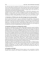
understood by both. The basic signals
25
shown in Figure 4.3.19 are similar
to those given in an EU Directive
37
and an HSE publication
38
.
Slingers, signallers and drivers should be properly trained, medically
fit and of a steady disposition. Detailed advice on the safe use of cranes,
lifting accessories and mobile cranes is given by Dickie, Short and
Hudson
26,27,28
.
4.3.6 Pressure systems
Pressure systems refer to any system of pipes, vessels, valves or other
equipment for containing or transferring gases and liquids at high
pressure.
However, as a result of moves to comply with EU directives, new
legislation in respect of pressure systems has polarised into two discrete
areas, manufacture of systems and their use. The earlier Pressure Systems
and Transportable Gas Containers Regulations 1989 have been revoked
and requirements concerning transportable gas containers have been
incorporated into the Carriage of Dangerous Goods (Classification,
Packaging and Labelling) and Use of Transportable Pressure Receptacles
Regulations 1996
32
.
4.3.6.1 Pressure equipment
The legislation on pressure equipment, the Pressure Equipment Regula-
tions 1999
33
(PER), is concerned with the quality of the equipment that is
manufactured and supplied and incorporates the requirements of the
Pressure Equipment Directive
34
. This Directive is aimed at reducing the
barriers to trade in respect of pressure equipment.
The Regulations define pressure equipment as:
Vessels, piping, safety accessories and pressure accessories;
where applicable, pressure equipment includes elements
attached to pressurised parts, such as flanges, nozzles,
couplings, supports, lifting lugs, and similar;
and fluid as:
Gases, liquids and vapours in pure phase as well as mixtures
thereof; a fluid may contain a suspension of solids.
It divides fluids into two groups, Group 1 are those fluids which are in
themselves hazardous to health, i.e. explosive, flammable, toxic or
oxidising. All other fluids are in Group 2.
The Regulations apply to all pressure equipment where the contained
pressure exceeds 0.5 bar above atmospheric pressure (7.25 psig). No
pressure equipment may be put on the market unless it complies with
these Regulations.
Safe use of machinery 761
Figure 4.3.19 Crane signals (BS 7121)
762 Safety at Work
A number of pressure equipment and assemblies, listed in schedule 1
of the Regulations, are excluded from these requirements.
Regulation 7 qualifies the different vessels and systems covered,
using a measure of either bar-litre (bar-L) (pressure in bars × volume in
litres) or a maximum allowable pressure (PS) as the criteria and
includes all:
(a) Unfired vessels handling fluids in Group 1 which must comply where
bar-L > 25 or PS > 200 bar and those handling fluids in Group 2 where
the criteria are bar-L 50 > or PS > 1000 bar. All fire extinguishers and
breathing apparatus air bottles are included.
(b) Fired and heated vessels for the generation of steam or super- heated
water, where there is a risk of overheating, operating at more than
110°C and having a volume > 2L. This includes pressure cookers.
(c) Piping handling Group 1 fluids having a nominal bore (ND) >25 mm
and Group 2 fluids having an ND > 32 mm and a product of ND× PS
> 1000 bar. For piping containing liquids whose vapour pressure at
the maximum allowable temperature (TS) < 0.5 bar handling Group 1
fluids where ND > 25 mm and ND × PS > 2000 bar and Group 2 fluids
where ND > 200 mm and ND × PS > 5000 bar.
Under reg. 8 all pressure equipment and systems that come within the
scope of the Regulations must:
i. Satisfy the relevant essential safety requirements (ESRs) listed in
schedule 2 of the Regulations. Conformity with a pertinent harmon-
ised standard presumes compliance with the ESRs.
ii. Have been subject to the appropriate conformity assessment proce-
dure which is outlined in schedule 3 of the Regulations.
iii. Carry the CE mark
iv. In fact, be safe.
Pressure systems and assemblies used for experimental purposes are
excluded from these requirements.
Any pressure equipment must carry the CE mark (reg. 9) and:
(a) be designed and manufactured in accordance with sound engineering
practice in order to ensure it is safe;
(b) be accompanied by adequate instructions for its safe use;
(c) have adequate identification marks; and
(d) be safe.
These requirements do not apply to pressure equipment for use outside
the EU, whether the equipment was manufactured in or just handled by
a Member State.
Pressure equipment is divided into four categories determined by the
type of vessel or system as described in reg. 7 and by its bar-L relationship
according to tables in schedule 3. For each category the relevant
conformity assessment procedure is listed in reg. 13(3) according to a
series of modules described in schedule 4. Conformity assessments may
Safe use of machinery 763
only be carried out by notified bodies who have been either approved by
the Secretary of State or notified to the EU commission.
Regulation 23 recognises that any pressure equipment or assembly that
carries the CE mark and is accompanied by a declaration of conformity
complies with these Regulations. Non-compliance is an offence that, on
conviction, carries a custodial sentence, a fine or both. However a defence
of due diligence is allowed.
4.3.6.2 Pressure systems safety
Once pressure equipment and assemblies have been installed and put
to work, it is essential that they are used and maintained in a manner
that ensures they remain safe throughout their operating life. Criteria,
procedures and requirements for ensuring this are contained in the
Pressure Systems Safety Regulations 2000 (PSSR)
35
which refers not
only to newly purchased and commissioned plant but also to pressure
equipment and systems that have been in service for a number of
years. The definitions contained in PER and PSSR are complementary
but with important differences in the definition of fluid. PER is
concerned with the pressure element of contained fluids and with the
safety integrity of the containing vessels and pipework in preventing
failures and leaks. PSSR, on the other hand, is concerned with
protecting the operator and others from the harmful effects of escaping
fluids, particularly steam at any pressure at or above atmospheric with
its potential to cause harm, such as scalds and burns, resulting from its
high level of latent heat. Conversely, PSSR is not concerned with the
chemical and biological hazards of the contained fluids since these are
the subject of other statutory provisions. PSSR is supported by an
ACoP
36
. Because of the widely differing operating circumstances of
pressure systems, the regulations recognise the need for a flexible
approach to ensuring safe operation and acknowledge the value of an
operating system based on an assessment of the possible risks should
the system fail.
The Regulations apply to all who design, manufacture, import, supply
or use any pressure system or vessel for work purposes, whether for
profit or not, but individual responsibilities extend only to matter under
a person’s direct control. There are a number of exclusions listed in
Schedule 1 which largely refer to pressure systems that are a necessary
ancillary part of other equipment or processes.
Pressure systems must (reg. 4):
i. be properly designed and constructed to prevent danger over the
whole of its expected operational life with allowance made for the
characteristics of the fluid contained;
ii. allow any examination necessary for ensuring the safe operation of
the system to be carried out;
iii. ensure that any access into vessels can be made without danger;
iv. be provided with suitable safety devices which, if they release the
contents, do so safely.
764 Safety at Work
Where a pressure system is designed, supplied or modified, the person
carrying out the work must provide all the information necessary for the
safe operation and maintenance of the system (reg. 5). If vessels are
involved, they must be marked with:
᭹ manufacturer’s name;
᭹ identifying number;
᭹ date of manufacture;
᭹ standard to which the vessel was built;
᭹ maximum (or minimum) allowable pressure; and
᭹ the design temperature.
Any imported vessel must carry the same information.
When a pressure system is being installed (reg. 6), the installer should
ensure:
᭹ only competent workmen and supervision are employed;
᭹ components have adequate foundations and supports;
᭹ suitable lifting equipment is available;
᭹ the component parts are in good order and are protected from
damage;
᭹ access for operating and carrying out examinations is not obstructed;
and
᭹ the system is cleaned before being put into operation.
The user is responsible for ensuring the pressure system is operated
within specified safe limits and that the design conditions are not
exceeded. A written scheme of examinations (reg. 8) must be prepared by
a competent person before the system is put into operation and should
include details of:
᭹ the operating conditions on which they are based;
᭹ the nature and frequency of examinations;
᭹ the preparations necessary for carrying out of examinations; and
᭹ the initial examination before the system is put to work.
Provisions should be made for the recording and storing the results of
these examinations (reg. 14). If operating conditions change or the system
is modified, the written scheme should be reviewed and adjusted
accordingly. Examinations are to be carried out in accordance with the
written scheme (reg. 9). A written copy of the report of the examination
has to be sent to the user within 28 days or if the user carries out
the examination, the report must be completed within 28 days. The
report should:
᭹ list the parts examined;
᭹ detail any repairs necessary to maintain the safety of the system and
the date by which those repairs must be completed;
᭹ nominate the date for the next examination; and
᭹ comment on the adequacy of the written scheme.
Safe use of machinery 765
Where repairs are necessary, the system must not be run until the repairs
have been completed. If it is necessary to operate the system beyond the
date of the next due examination without it being examined, this should
only be with the agreement of the examiner and after notifying the
enforcing authority. On mobile systems, the date of the next examination
must be clearly and indelibly marked.
Preparations necessary to ensure that examination can be carried out
safely should include:
᭹ ensuring the system is cool;
᭹ dispersing any toxic or harmful gases or fumes;
᭹ if the lagging contains asbestos, warning the examiner and ensuring
appropriate precautions are taken;
᭹ providing suitable means of access, including staging if necessary;
᭹ isolating the system from others that may still be pressurised; and
᭹ removing components and safety devices as appropriate.
If the examiner is of the opinion that the system is likely to cause
imminent danger unless repairs are carried out (reg. 10), he must notify
the user in writing immediately specifying the necessary repairs. A copy
of the report must be sent to the enforcing authority within 14 days. The
user must ensure that the system is not used until the required repairs
have been carried out. It is the responsibility of those carrying out the
work to ensure that any modification or repairs do not reduce the safety
of operation of the system (reg. 13).
The user of a pressure system must ensure that the system operators
are fully instructed in the safe operating techniques (reg. 11) including
maximum operating limits and the action to be taken in an emergency.
Operating instructions should include start-up and shut-down proce-
dures, the functions and use of controls and dealing with potentially
hazardous situations. Any vessel intended to be operated at atmospheric
pressure (reg. 15) should be provided with a secure, unrestricted,
connection direct to atmosphere.
Pressure systems must be kept properly maintained (reg. 12) to ensure
that they can continue operating with safety. The extent of the
maintenance will be determined by consideration of:
(a) the age of the system;
(b) the materials contained and operating conditions;
(c) the working environment;
(d) the maker’s maintenance recommendations;
(e) the maintenance history and modifications made;
(f) recommendations from periodic examinations; and
(g) the results of a risk assessment of the likely effects of a system
failure.
Records must be kept (reg. 14) of:
᭹ the technical and operating instructions provided by the supplier;
᭹ all reports of periodic examinations;
766 Safety at Work
᭹ details of any modifications or repairs; and
᭹ the maintenance and operating logs of the system.
The records should be kept at either the operating site of the system or the
office from which the system is controlled. They can be written (hard
copy) or in electronic form provided they cannot be interfered with, i.e.
read-only format. Whichever method is used it must be such that a hard
copy can easily be produced if requested by the enforcing authority.
In any proceedings for an offence under these Regulations, a defence
can be pleaded that:
i. the offence was due to the act or default of another person; or
ii. all due diligence had been exercised.
In either case, the defendant must justify his defence plea.
4.3.7 Coda
The use of machines and machinery is an essential fact of industrial and
commercial life. But there is no reason why the use of this equipment
should cause damage or injury. Over the years, manufacturing standards
and operating techniques have been developed that ensure safe and
efficient operation over the economic life of the equipment. It is up to the
maker and user to ensure that those standards and practices are adhered
to so that any risks from the use of the equipment are kept to a
minimum.
References
1. European Union, Council Directive on the approximation of the laws of Member States relating
to machinery, No. 89/392/EEC as amended by Directive No 91/368/EEC, EU,
Luxembourg (1991) and consolidated in Directive No. 98/37/EC
2. European Union, Council Directive concerning the minimum health and safety requirements
for the use of work equipment by workers at work, as amended by Directive No. 95/63/EC,
EU, Luxembourg (1995)
3. Health and Safety Executive, Legal Series booklet No. L22, Safe use of work equipment.
Provision and Use of Work Equipment Regulations 1998. Approved Code of Practice. HSE
Books, Sudbury (1998)
4. British Standards Institution, BS EN 953, Safety of machinery – Guards – General
requirements for the design and construction of fixed and movable guards, BSI, London
(1998)
5. British Standards Institution, BS EN 1088, Safety of machinery – Interlocking devices
associated with guards – Principles for design and selection, BSI, London (1995)
6. British Standards Institution, Published Document, PD 5304:2000, Safe use of machinery,
BSI, London (2000)
7. British Standards Institution, BS EN 294, Safety of machinery – Safety distances to prevent
danger zones being reached by upper limbs, BSI, London (1992)
8. British Standards Institution, BS EN 349, Safety of machinery – Minimum gaps to avoid
crushing of parts of the human body, BSI, London (1993)
9. British Standards Institution, BS EN 999, Safety of machinery – The positioning of protective
equipment in respect of approach speeds of parts of the human body, BSI, London
10. Uddin v. Associated Portland Cement Manufacturers Ltd [1965] 2 All ER 213
Safe use of machinery 767
11. Close v. Steel Company of Wales [1962] AC 367; [1961] 2 All ER 953, HL
12. British Standards Institution, BS EN 292–1, Safety of Machinery – Basic concepts and general
principles for design – Part 2: Basic terminology and methodology, BSI, London (1991)
13. British Standards Institution, BS EN 292–2, Safety of machinery – Basic concepts and general
principles for design – Part 2: Technical principles and specifications, BSI, London (1991) and
Part 2/Al (1995)
14. British Standards Institution, BS EN 1050, Safety of machinery – Principles for risk
assessment, BSI, London (1997)
15. British Standards Institution, BS EN 811, Safety of machinery – Safety distances to prevent
danger zones being reached by lower limbs, BSI, London (1997)
16. British Standards Institution, BS EN 574, Safety of machinery – Two-hand control devices –
Functional aspects – Principles for design, BSI, London (1996)
17. British Standards Institution, BS EN 547, Safety of machinery – Human body dimensions (7
parts), BSI, London (parts 1 & 2, 1996)
18. Health and Safety Executive, Publication L117, Rider operated lift trucks: Operator training,
Approved Code of Practice and guidance, HSE Books, Sudbury (1999)
19. Society of Light and Lighting, Code for Lighting 2000, CIBSE, London (2000)
20. Health and Safety Executive, Guidance booklet No. HSG 38, Lighting at work, HSE
Books, Sudbury (1998)
21. Health and Safety Executive, Guidance Note No. PM28, Working platforms on fork lift
trucks, HSE Books, Sudbury (2000)
22. Health and Safety Executive, Guidance booklet No. HSG 6, Safety in working with lift
trucks, HSE Books, Sudbury (2000)
23. European Union, Council Directive on the approximation of the laws of Member States relating
to lifts, No. 95/16/EC, EU, Luxembourg (1995)
24. Health and Safety Executive, Publication L113, Safe use of lifting equipment, Lifting
Operations and Lifting Equipment Regulations 1998. Approved Code of Practice, HSE Books,
Sudbury (1998)
25. British Standards Institution, BS 7121, Code of practice for the safe use of cranes, Part 1 –
General; Part 2 – Inspection, testing and examination, BSI, London
26. Dickie, D.E., Lifting Tackle Manual (Ed. Douglas Short), Butterworths, London (1981)
27. Dickie, D.E., Crane Handbook; (Ed. Douglas Short), Butterworth, London (1981)
28. Dickie, D.E., Mobile Crane Manual (Ed. Hudson, R.W.), Butterworth, London (1985)
29. Health and Safety Executive, Publication L112, Safe use of power presses, HSE Books,
Sudbury (1998)
30. Health and Safety Executive, Publication L114, Safe use of woodworking machinery, HSE
Books, Sudbury (1998)
31. Ridley, J. and Pearce, R., Safety with machinery, Butterworth-Heinemann, Oxford
(2002)
32. The Carriage of Dangerous Goods (Classification, Packaging and Labelling) and Use of
Transportable Pressure Containers Regulations 1996, The Stationery Office, London
(1996)
33. The Pressure Equipment Regulations 1999, The Stationery Office, London (1999)
34. European Union, Council Directive on the approximation of the laws of Member States
concerning pressure equipment, No. 97/23/EC, EU, Luxembourg (1997)
35. The Pressure Systems Safety Regulations 2000, The Stationery Office, London (2000)
36. Health and Safety Executive, Publication L122, Safety of pressure systems. Pressure Systems
Safety Regulations 2000. Approved Code of Practice, HSE Books, Sudbury (2000)
37. European Union, Directive on the minimum requirements for the provision of safety signs at
work, No. 92/58/EEC, EU, Luxembourg (1992)
38. Health and Safety Executive, Publication L64, Safety signs and signals. The Health and
Safety (Safety Signs and Signals) Regulations 1996, HSE Books, Sudbury (2000)
Further reading
King, R. W. and Magid, J., Industrial Hazard and Safety Handbook, pp. 567–603, Butterworth-
Heinemann, Oxford (1979)
Ridley, J. and Pearce, R., Safety with machinery, Butterworth Heinemann, Oxford (2002)
768 Safety at Work
Health and Safety Executive, the following publications which are available from HSE
Books, Sudbury:
Guidance booklets:
HSG 39 Compressed air safety (1998)
HSG 54 The maintenance, examination and testing of local exhaust ventilation (1998)
HSG 87 Safety in the remote diagnosis of manufacturing plant and equipment (1995)
HSG 89 Safeguarding agricultural machinery. Advice for designers, manufacturers, suppliers
and users (1998)
HSG 93 The assessment of pressure vessels operating at low temperatures (1993)
HSG 113 Lift trucks in potentially flammable atmospheres (1996)
HSG 129 Health and safety in engineering workshops (1999)
HSG 136 Workplace transport safety: Guidance for employers (1995)
HSG 172 Health and safety in sawmilling. A run-of-the-mill business? (1997)
HSG 180 Application of electro-sensitive protective equipment using light curtains and light
beam devices to machinery (1999)
Guidance notes:
PM24 Safety in rack and pinion hoists (1981)
PM28 Working platforms on lift trucks (2000)
PM55 Safe working with overhead travelling cranes (1985)
PM63 Inclined hoists used in building and construction work (1987)
PM65 Worker protection at crocodile (alligator) shears (1986)
PM66 Scrap baling machines (1986)
PM73 Safety at autoclaves (1998)
PM79 Power presses. Thorough examination and testing (1995)
PM83 Drilling machines. Guarding of spindles and attachments (1998)
769
Chapter 4.4
Electricity
E. G. Hooper and revised by Chris Buck
4.4.1 Alternating and direct currents
4.4.1.1 Alternating current
An alternating current (ac) is induced in a conductor rotating in a
magnetic field. The value of the current and its direction of flow in the
conductor depends upon the relative position of the conductor to the
magnetic flux. During one revolution of the conductor the induced
current will increase from zero to maximum value (positive), back to zero,
then to maximum value in the opposite direction (negative) and, finally,
back to zero again having completed one cycle. A graph plotted to show
the variation of this current with time follows a standard sine wave. The
number of cycles completed per second, each comprising one positive
and one negative half cycle, is referred to as the frequency of the supply,
measured in hertz (Hz). Mains electricity is supplied in the UK as ac at a
nominal frequency of 50 Hz (50 cycles per second).
4.4.1.2 Direct current
Direct current (dc) has a constant positive value above zero and flows in
one direction only, unlike ac. A simple example of direct current is that
produced by a standard dry battery.
DC is really ac which has its positive or negative surges rectified to
provide the uni-directional flow. In a dc generator the natural ac
produced is rectified to dc by the commutator.
DC will be found in industry in the form of battery supplies for
electrically powered works plant, such as fork lift trucks, together with
associated battery charging equipment. Otherwise, dc, obtained by
rectification of the mains ac supply, will be encountered only for specialist
applications, e.g. electroplating.
Danger from electricity may arise irrespective of whether it is ac or dc.
Where dc is derived from ac supply the process of rectification will result
in some superimposed ripple from the original ac waveform. Where this
exceeds 10%, the electrical shock hazard must be considered to be the
770 Safety at Work
same as for an ac supply of equivalent voltage. Additionally, both ac and
dc can cause injury as a result of short circuit flashover. The dangers of
electricity are discussed in more detail later in this chapter.
4.4.2 Electricity supply
Alternating current electricity is generated in thermal power stations
(coal-, gas- and oil-fired), in nuclear power stations, as well as using
natural resources (e.g. wind farms). It is then transmitted by way of
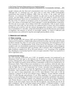
overhead lines at 400 kV (i.e. at 400 000 volts) (Figure 4.4.1), 275 kV or
132 kV to distribution substations where it is transformed down to 33 kV
or 11 kV for distribution to large factories, or further transformed down to
230 V for use in domestic and commercial premises and smaller
factories.
Following privatisation, many changes have and are still taking place
in the electricity industry. The demand for electricity varies considerably
from day to day as well as throughout each day. Generation must be
matched to meet this continually varying demand, ensuring that there is
always sufficient generating capacity available at minimum cost. This is
achieved through arrangements operated by the electricity pool. There is
now an open market for all power users to shop around suppliers to
achieve the best price.
Electricity is received by most industrial and commercial consumers as
a ‘three-phase four-wire’ supply at a nominal voltage of 400/230 V. The
three phases are distinguished by the standard colours red, yellow and
blue, the fourth wire of the supply serving as a common neutral
conductor. There are proposals to adopt European standard phase colours
at a future date which will result in a change from the present colours.
The individual phase voltages (230 V) are equally displaced timewise
(phase displacement of 120°) and because of this the voltage across
phases is higher. Three-phase supplies can be used to supply both single-
phase equipment (with the loads balanced as equally as possible between
the three phases) or three-phase equipment such as to large motors.
Consumers with large energy requirements often find it more economi-
cal and convenient to receive electricity at 11 kV and to transform it down
to the lower values as required. In all cases, however, it is essential that
the consumer’s electrical installation and equipment, both fixed and
portable, meet good standards of design, construction and protection, are
adequately maintained and correctly used.
The British Standards Institution
1
(BSI) issues standards and codes
giving guidance on electrical safety matters. One such standard is BS
7671, otherwise known as the IEE Wiring Regulations
2
. These non-
statutory Regulations specify requirements for low voltage electrical
installations, i.e. those operating at voltages up to 1000 V. BS 7671 takes
account of the technical matters contained in a number of European
Standard Harmonisation Documents published by the European Com-
mittee for Electrotechnical Standardisation (CENELEC). However, it is
important to appreciate the legal obligations relating to the safe use of
electricity and electrical machinery at places of work.
Electricity 771
Figures 4.4.1 400 kV suspension towers on the National Grid’s Sizewell-Sundon
400 kV transmission line. (Courtesy National Grid)
772 Safety at Work
The Health and Safety at Work etc. Act 1974 (HSW) is an enabling Act
providing a legal framework for the promotion of health and safety at all
places of work. Although the Act says nothing specific about electricity it
does require, among other things, the provision of safety systems and
methods of work; safe means of access, egress and safe places of
employment; and adequate instruction and supervision. These require-
ments have wide application but they are, in general terms, also relevant
to the safe use of electricity. But for specific advice on the electrical legal
requirements we must turn to a set of Regulations
3
made under the HSW
Act.
4.4.3 Statutory requirements
4.4.3.1 The Electricity at Work Regulations 1989
The Electricity at Work Regulations 1989 (EAW) is the primary piece of
legislation dealing specifically with electricity and came into force on 1
April 1990. Since these Regulations were made under the umbrella of the
HSW they apply in all cases where the parent Act applies. They are thus
work activity, rather than premises, related and are therefore of wide
application. The Regulations do not implement a corresponding EU
Directive, as is the case with other health and safety legislation, and
therefore the requirements are enforceable only in Great Britain. Some of
the individual regulations are relevant to all industries while others apply
only to mines. Separate, but virtually identical, Regulations have been
made for Northern Ireland – the Electricity at Work Regulations
(Northern Ireland) 1991. The requirements of the Regulations now also
apply to offshore installations by virtue of the Offshore (Electricity and
Noise) Regulations 1997.
In line with modern health and safety legislation, the EAW are ‘goal
setting’ aimed at specifying, albeit in general terms, the fundamental
requirements for achieving electrical safety. Thus they provide flexibility
to accommodate future electrical developments. They specify the ends to
be achieved rather than the means for achieving them. With regard to the
latter, guidance is provided in a number of booklets published by the HSE
as well as in BSI and other authoritative guidance. The main supporting
documents are:
1 a Memorandum of Guidance
4
, and
2 two Approved Codes of Practice
5,6
dealing respectively with the use of
electricity in mines and in quarries.
The Memorandum of Guidance referred to above gives technical and
legal guidance on the Regulations and provides a source of practical help.
Similarly, the two Codes of Practice provide essential advice for mines
and quarries.
The Electricity at Work Regulations comprise 33 individual regulations
which place firm responsibilities on employers, the self-employed,
managers of mines and of quarries and employees to comply as far as
they relate to matters within their control. Additionally, employees have
Electricity 773
a duty to co-operate with their employers so far as is necessary for the
employers to comply with the Regulations.
Topics covered by particular regulations include:
(a) Construction and maintenance of systems, work activities and
protective equipment (Reg. 4).
(b) Strength and capability of electrical equipment (Reg. 5).
(c) Adverse and hazardous environments (Reg. 6).
(d) Insulation, protection and placing of conductors (Reg. 7).
(e) Earthing and other suitable precautions (Reg. 8).
(f) Integrity of ‘referenced’ conductors (Reg. 9).
(g) Connections (Reg. 10).
(h) Means for protecting from excess current, for cutting off supply and
isolation (Regs. 11 and 12).
(i) Precautions for work on dead equipment and on or near live
conductors (Regs. 13 and 14).
(j) Working space, lighting and access (Reg. 15).
(k) Persons to be competent to prevent danger and injury (Reg. 16).
(l) Regulations applicable to mines only (Regs 17–28).
4.4.3.2 Status of regulations
Certain of the individual regulations are subject to the qualification ‘so far
as is reasonably practicable’. This means that any action contemplated
should be based on a judgement balancing the perceived risk against the
cost of eliminating it, or at least reducing it to an acceptable level; in other
words a risk assessment.
The remaining regulations are of an ‘absolute’ nature, which means
that their requirements must be met regardless of cost. Nevertheless, in
the event of a criminal prosecution for an alleged breach of statutory duty
under one of these regulations, regulation 29 allows a defence to be
pleaded that all reasonable steps were taken and all due diligence was
exercised to avoid the commission of the offence.
4.4.4 Voltage levels
Unlike their predecessors, the 1989 Regulations apply equally to all
systems and equipment irrespective of the voltage level. The duty is to
avoid danger and prevent injury from electricity. Voltage is but one factor
determining the presence of danger and, therefore, the risk of injury;
examples of other matters requiring consideration when evaluating the
electrical risk are the equipment type, its standard of construction and the
nature of the work environment.
4.4.5 Electrical accidents
Electricity is a safe and efficient form of energy and its benefits to
mankind as a convenient source of lighting, heating and power are
774 Safety at Work
obvious. But, if electricity is misused, it can be dangerous – a statement of
the obvious, but one which must be made so as to keep the matter in
proper perspective.
In the UK, every year, up to 20 people may be killed, at work, as a
result of an electrical accident. In addition, around 750 or so are
injured. These figures, considering the widespread use of electricity in
industry and when compared with the numbers killed and injured as
a result of other types of accident, are relatively small. Nevertheless, a
knowledge of electrical safety is important because, by comparison
with the proportion of serious injury resulting from accidents arising
from all causes, an electrical accident is more likely to lead to serious
injury. There is the potential also for expensive damage to plant and
property due to fires of electrical origin, e.g the overloading of
cables.
4.4.6 The basic electrical circuit
For an electrical current to do its job of providing lighting, heating and
power, it must move safely from its source, through the conducting
path and back from whence it came. In short, electric current requires a
suitable circuit to assist its flow without danger. The circuit must be of
suitable conducting material, e.g. copper, covered with a suitable
insulating material (to stop the current ‘leaking’ out) such as PVC or
rubber.
For an electrical current measured in amperes to flow in a circuit it
requires pressure (voltage), measured in volts. As it flows it encounters
resistance from the circuit and apparatus and this characteristic is
measured in ohms.
This relationship between volts, amps and ohms is brought together in
the famous Ohm’s law known to most schoolboys. Thus, to put it simply,
the current in a circuit is proportional to the voltage driving it and
inversely proportional to the resistance it has to overcome:
amps =
volts
ohms
(1)
Alternatively, this may be written as:
ohms =
volts
amps
(2)
or
volts = amps ϫ ohms (3)
A further useful relationship is that between power (measured in watts)
and the voltage and current. Thus:
watts = volts ϫ amps (4)
Electricity 775
From Ohm’s law, this may be expressed also as:
watts = amps
2
ϫ ohms (5)
or watts =
volts
2
ohms
(6)
4.4.6.1 Impedance
As an alternating current passes around a circuit under the action of an
applied voltage it is impeded in its flow. This may be due to the presence
in the circuit of resistance, inductance or capacitance, the combined effect
of which is called the impedance and is measured in ohms.
In a pure resistance circuit the applied voltage has to overcome the
ohmic value of the resistance as is the case for direct current (see
equations (1) to (6) above).
If, however, the circuit contains inductance, such as the presence of a
coil, the alternating magnetic field set up by the alternating current will
induce a voltage in the coil which will oppose the applied voltage and
cause the current to lag vectorially behind the voltage (up to 90° where
the circuit contains pure inductance only). This property is called
reactance and is measured in ohms. Sometimes a circuit may contain a
capacitor: the applied voltage ‘charges’ the capacitor and the effect is such
as to cause the current vectorially to lead the voltage. This property is also
called reactance. Now most circuits contain resistance, inductance and
capacitance in various quantities, and the effect of impedance is found as
follows:
impedance
2
= resistance
2
+ reactance
2
Strictly speaking this is a vectorial calculation. It is beyond the scope of
this section to go further into these relationships and readers are referred
to a standard textbook on electricity
7
and to BS 4727
8
.
4.4.7 Dangers from electricity
It has been said that properly used electricity is not dangerous but out of
control it can cause harm, if it passes through a human body, by
producing electric shock and/or burns. Electricity’s heating effect
can also cause fire but we will first deal with the electric shock
phenomenon.
4.4.7.1 Electric shock
If a person is in contact with earthed metalwork or is inadequately
insulated from earth then, because the human body and the earth itself
are good conductors of electricity, they can form part of a circuit (albeit an
776 Safety at Work
abnormal one) through which electricity, under fault conditions, can flow.
How can such fault conditions occur?
If, for any reason, there was a breakdown of insulation in a part of an
electric circuit or in any apparatus such as, say, a hand-held metal-cased
electric drill, it is conceivable that current would flow external to this
supply circuit, if a path were available. For example, the metalwork of the
drill may be in contact with a live internal conductor at the point of
insulation breakdown (an example of indirect contact). Or, take the
example of someone working at a switch or socket outlet from which the
cover had been removed before the electricity supply had been isolated.
In such cases the person concerned could touch live metal or a live
terminal and, if the conditions were right, would thereby cause an electric
current to flow through his body to earth (an example of direct contact).
If the total resistance of the earth fault path were of a sufficiently low
value, the current could kill or maim.
Electric shock is a term that relates to the consequences of current flow
through the body’s nerves, muscles and organs and thereby causing
disturbance to normal function. Owing to a current’s heating effect the
body tissue could also be damaged by burns. A particular danger with
electric shock from alternating current is that it so often causes the person
concerned to maintain an involuntary grip on the live metal or conductor
(particularly hand-held electric tools) and this prolongs current flow. The
passage of shock current through the body may interfere with the correct
functioning of the lungs and heart. Death could occur when the rhythm
of the heart is disturbed such as to affect blood flow and hence the supply
of oxygen to the brain, a condition that is known as ventricular
fibrillation. Unless prompt medical attention is given, ventricular
fibrillation can be irreversible. However, it is still fortunately the case that
most electric shock victims recover without permanent disability or
lasting effect.
Although the effect of a direct current shock is generally not as
dangerous as with ac (there is no dangerous involuntary grip phenom-
enon for example), it is recommended that similar precautions against
shock be taken. In any case it will be recalled from section 4.1.2 that the
dc electrical shock hazard could be similar to that of an equivalent ac
voltage as a result of the amount of superimposed ripple.
The severity of an electrical shock depends on a number of factors, the
most significant of which are the combination of the magnitude and the
duration of the flow of shock current through the body.
Personal sensitivity to electric shock varies somewhat with age, sex,
heart condition etc., but for an average person the relationship between
shock current, and time for which the body can accommodate it, is given
by a formula of the following kind:
current =
116
ͱ
time
where the current is measured in milliamps (mA) and the time is
measured in seconds (s). Above the duration of one heart beat a lower
current threshold is recommended.
Electricity 777
Thus a 50 mA shock current (i.e. 0.05 A) could probably flow through a
body, without much danger, for up to 4 seconds; whereas a 500 mA
current (0.5 A) flowing for only 50 ms (0.05 s) could be fatal.
The maximum safe ‘let go’ current is less than 10 mA, whereas 20 mA
to 40 mA directly across the chest could arrest respiration or restrict
breathing; currents above 500 mA flowing for as little as 50 ms can be
fatal. However, even ‘safe’ currents at the level of about 5 mA to 10 mA
could still cause a minor shock sensation and cause someone to fall if
working at a height.
From all this it will be concluded that at normal mains voltage of 230 V,
and given the average value of resistance of a human body at 1500 ⍀, the
current flowing through the body would, from equation (1), be a
maximum of
230
1500
= 0.15 A approximately (150 mA)
– a dangerously high value. Under normal circumstances there will be
additional resistances (or impedances as they are more correctly called)
such as, for example, the resistance of the circuit, the earth electrode, and
any footwear worn. It must also be remembered that body resistance
varies from person to person depending upon biological, environmental
and climatic conditions. But even so, given the very small value of current
that could cause harm, all possible sources of contact with live electric
parts must be avoided. Live work presents a high risk since a hand-to-
hand shock path may be established where one hand comes into contact
with an exposed live part while the other is simultaneously touching the
earthed metal equipment case. The precautions to be taken are discussed
in later sections of this chapter.
4.4.7.2 Burns
Burn injuries may be associated with shock and can be seen as burn
marks on the body at the points of current entry and exit or may also
occur in the burning of internal tissue. However, severe burn injuries are
more likely to arise as a consequence of short circuit flashover. In fact the
number of fatalities arising from this latter cause is similar to that
resulting directly from electric shock.
Short circuit flashovers caused during the course of live work are likely
to result in serious injury for the simple reason that the worker is in close
proximity to and probably directly facing the equipment that has been
inadvertently short circuited. The extent of the flashover will depend on
the amount of electrical energy available to flow into the fault. This will
be determined by the fault level (the amount of current that the incoming
electrical supply is capable of feeding into the fault) and the speed of
operation of the electrical protection, e.g. a fuse or circuit breaker, to
interrupt the flow of fault current.
778 Safety at Work
In the case of a factory installation the fault level is likely to be of the
order of several thousand amperes. This large current will be capable of
generating severe arcing during the short period required for the
electrical protective devices to see the fault and safely disconnect the
supply. Many will be aware of the flashover capability from even low
voltage dc supplies, such as a 12 V car battery, if the terminals are
accidentally shorted by dropping a metal tool across them.
4.4.7.3 Fires
Fires may occur due to a variety of electrical problems, in particular as a
result of the overheating of cables or equipment, arcing due to loose
connections or the use of unsuitable electrical equipment in a flammable
atmosphere. Such problems often arise due to deficiencies in the design
or construction of the electrical installation or incorrect equipment
specification. The EAW address all these issues by specifying funda-
mental requirements to ensure that the design and construction of
installations is such as to prevent, so far as is reasonably practicable,
danger.
4.4.8 Protective means
4.4.8.1 Earthing and other suitable precautions
To prevent danger where it is ‘reasonably foreseeable’ that a conductor
(other than a circuit conductor) may become charged with electricity,
earthing or other suitable precautions need to be taken. In the case of
earthing, all metalwork forming part of the electrical installation (metal
conduit and trunking housing cables) or apparatus (metal equipment
casings of switchgear, transformers, motors etc.) should be adequately
and solidly connected to earth. Such earthing is provided by means of
‘protective conductors’ which may comprise a separate conductor, as in
the ‘twin and earth’ cable or, where appropriate, the cable armouring or
metal conduit or trunking. However, flexible or pliable conduit is not
acceptable for this purpose.
It is important to ensure that the resistance of the earth return path,
comprising the protective conductor and connection with earth, is as low
as possible. This is to ensure that, in the event of an earth fault, there will be
sufficient current to ‘blow’ the fuse or operate any other form of device
protecting the circuit in question. The IEE Wiring Regulations (BS7671)
2
specify maximum permitted disconnection times for different types of
installation. There is also a BS Code of Practice on the subject of earthing
9
.
4.4.8.2 Work precautions
When work is to be carried out on a part of a circuit or piece of electrical
equipment, certain precautions need to be taken to protect the worker
Electricity 779
concerned from electrical danger. The electricity supply should first of all
be switched out, locked off and warning notices posted. This ensures that
the circuit or apparatus being worked on is effectively electrically isolated
and cannot become live.
Using a suitable voltage proving device, that part of the circuit to be
worked on should be checked to ensure that it is dead before work is
allowed to commence. Correct operation of the proving device should be
confirmed immediately before and after use.
In some circumstances further precautions will need to be taken, such
as earthing, to counter the effects of any stored or induced electrical
charge. A permit to work system (PTW), explained in more detail in
section 4.4.10, may also be used. Although EAW regulation 14 permits
live working this must first be properly justified and then suitable
precautions must be taken to prevent injury (an absolute duty!). Thus
dead working is the norm and the preferred choice.
The HSE have published a number of guidance documents concerning
those work activities where previous accident history has shown a need
for more understanding to ensure electrical safety
10,11,12
.
4.4.8.3 Insulation
Mention has already been made of the need to ensure that electrical
conductors etc. are adequately insulated. Insulating material has
extremely high resistance values to prevent electric current flowing
through it. The principle of insulation is used when work has necessarily
to be carried out at or near uninsulated live parts. Such parts should
always be made dead if at all possible. If this cannot be done then
properly trained people, competent to do the work, can make use of
protective equipment (insulated tools, gloves, mats and screening
materials) to prevent electrical shock and short circuit flashover. The
provision and use of such equipment must meet the requirements of the
Personal Protective Equipment at Work Regulations 1992 as well as
regulation 4(4) of EAW. It is important that all protective equipment
provided is suitable for the intended use (i.e. designed and constructed to
an appropriate specification such as a British Standard), adequately
maintained and properly used. A number of BSs cover the specification of
such equipment
13,14,15,16
.
4.4.8.4 Fuses
A fuse is essentially a thin wire, placed in a circuit, of such size as would
melt at a predetermined value of current flow and therefore cut off the
current to that circuit. Obviously a properly rated fuse is a most useful
precaution because, in the event of abnormal conditions such as a fault,
when excess current flows, the fuse would ‘blow’ and protect the circuit
or apparatus from further damage. A fuse needs to be capable of
responding to the following types of abnormal circuit conditions: