Cephalometry A Color Atlas and Manual - part 9 docx
Bạn đang xem bản rút gọn của tài liệu. Xem và tải ngay bản đầy đủ của tài liệu tại đây (2.87 MB, 37 trang )
CHAPTER 8
291
3-D Cephalometry and Craniofacial Growth
Cephalometric radiography has yielded fundamental
knowledge on craniofacial morphogenesis and led to
the development of craniofacial growth concepts (e.g.
Moss’ functional matrix theory, Enlow’s counterpart
theory, Delaire’s architectural craniofacial analysis).
Huge amounts of cephalometric data have been col-
lected, and cephalometric reference data have been de-
veloped by different research groups (e.g. Bolton stan-
dards of dentofacial developmental growth, cephalo-
metric standards by Riolo and co-workers).
Craniofacial growth and development is a compos-
ite result of different fundamental growth processes
that take place simultaneously in different regional de-
velopmental fields.Each of these has its proper amount
and direction of growth which determine its growth
vector. According to Enlow’s counterpart theory, three
principal craniofacial growing parts exist, each having
its proper development timing although they are all in-
terrelated: the neurocranium (brain) and basicranium
(cranial base); the airway; and the oral region. The vis-
cerocranium (the face) develops in phylogenetic asso-
ciation with the neurocranium, with the basicranium
as a template in between.
Craniofacial growth and development of the visce-
rocranium and neurocranium are based on two differ-
ent processes of skeletal movement that are interrelat-
ed and occur simultaneously: displacement and re-
modelling. Primary displacement involves a bony dis-
placement away from the other skeletal parts triggered
by the traction forces of the expanding functional soft
tissue matrix (the so-called carry effect) in order to
create space for enlargement and relocation of bones.
During primary displacement the moving bone and
other skeletal parts are growing simultaneously, while
in secondary displacement the displacement of a bone
is not directly related to its own enlargement. Remod-
elling is a different process that takes place through
patterns of deposition and resorption, in an opposite
direction to primary displacement.The amount of new
bone regeneration by bony deposition is equal to the
amount of primary bone displacement. During this
complex process, developmental growth rotations and
growth compensations (e.g. palatal, mandibular verti-
cal ramus, dento-alveolar) take place as developmental
adjustments in order to create balance during cranio-
facial development.
Although conventional cephalometry has made a
huge contribution to the current concepts on craniofa-
cial growth and development, it has the important lim-
itation that it is two-dimensional. The separate effects
of craniofacial growth by displacement or by deposi-
tion and resorption are not distinguishable. A conven-
tional lateral cephalogram, for example, can show re-
modelling changes on the anterior and posterior sur-
face of the vertical mandibular ramus but cannot visu-
alize what is happening transversely. This chapter
represents an introduction to the potential of 3-D
cephalometry for further investigation of craniofacial
growth patterns. It aims to illustrate some of the con-
cepts of Enlow’s counterpart theory of facial growth.
Superimposition of 3-D hard tissue surface representa-
tions and serial 3-D cephalometric tracings of a new-
born, a 6-year-old and an adult cadaver skull are used
to illustrate the composite result of multi-directional
growth changes relative to the 3-D cephalometric ref-
erence system based on the Sella and Nasion land-
marks (Chap. 3). It is important to keep in mind that,
according to Enlow, superimposition of cephalometric
tracings is appropriate and valid, as long as one is
aware that the cranial base also undergoes remodelling
during craniofacial growth and that therefore cranial
base-related landmarks such as Sella and Nasion are
not absolutely fixed.
CHAPTER 8
292
3-D Cephalometry and Craniofacial Growth
8.1
The Basicranium as a Template for Facial Growth
Human craniofacial growth and development is basi-
cally not different from that in other mammalian
species. In mammals the neurocranium (brain) deter-
mines in a phylogenetic relationship the development
and growth of the viscerocranium (face),with the basi-
cranium (cranial base) as a template in between. The
enormous expansion of the human brain led to expan-
sion (Fig. 8.1) and bending (so-called basicranial flex-
ure; Fig. 8.2) of the basicranium. This process resulted
in an inferior and posterior rotation of the human face
with forward rotation of the orbits. Therefore, the
architectonic morphologic plan of the human face is
wide and vertically flattened, in contrast to the narrow
and long viscerocranium of phylogenetically lower
mammalian species (e.g. sheep; Figs. 8.3, 8.4).
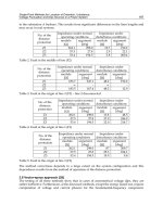
Fig. 8.1. Comparison of the human and sheep basicranium illustrates the
enormous enlargement of the human anterior and middle cranial fossa due to
expansion of the frontal and temporal cerebral lobes. Endocranial skull base
view (3-D CT hard tissue surface representations of adult sheep and human
cadaver skulls)
CHAPTER 8
293
8.1 The Basicranium as a Template for Facial Growth
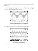
Fig. 8.2 a, b. Virtual lateral cephalograms with superimposed tracing of the cranial base (Basion–Sella–Nasion) show the typical flexure of the human basi-
cranium with relocation of the foramen magnum in order to allow vertical passing of the spinal cord into the vertical directed vertebral column (b).In contrast,the
basicranium of the sheep skull is flat with the foramen magnum located in the posterior region to allow horizontal passing of the spinal cord into the horizontally
directed vertebral column (a).(adult sheep and human cadaver skulls)
ab
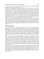
Fig. 8.3. Comparison of frontal views of a sheep skull and a human skull illus-
trates the typical wide human face with squared zygomatic bones,a small nasal
airway and the developmental horizontal and vertical rotation of the orbits to
the midline due to frontal and temporal cerebral lobe expansion.In contrast the
sheep has a narrow muzzle with a large nasal space,divergent orbital axes and
a large intraorbital distance.(3-D CT hard tissue surface representations of adult
sheep and human cadaver skulls)
CHAPTER 8
294
3-D Cephalometry and Craniofacial Growth
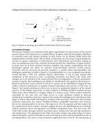
Fig. 8.4. Comparison of left profile views of a sheep skull and a human skull shows the forward remodelling rotation of the upper part of the human face and
posterior rotation of the lower part due to the basicranial flexure.The human face is typically vertically flattened with an upright bulbous forehead and presents
an anterior and inferior rotation of the orbits due to expansion of the frontal and temporal cerebral lobes.In contrast,the sheep displays a protruding muzzle and
divergent orbits in front of the basicranium.(3-D CT hard tissue surface representations of adult sheep and human cadaver skulls)
CHAPTER 8
295
8.1 The Basicranium as a Template for Facial Growth
The basicranium acts as a template for the growth
fields in which the nasomaxillary complex, the zygo-
matic bones and the mandible develop. In infancy the
human face appears wide and short due to the wide
basicranium and the small mandible (Fig. 8.5). The
increase in basicranial flexure (Fig. 8.6) and the expan-
sion of the airway and oral region result in vertical
changes, with lowering of the mandible by an increase
in vertical mandibular ramus height. Ideally this re-
sults in a balanced face, which is proportionate in
width and height. If the vertical changes are increased,
this process leads to the dolichocephalic head form,
with a narrower and longer face (so-called long-face).
If, in contrast, the vertical changes are decreased, the
result is the brachycephalic head form, with a wider
and shorter face (so-called short-face).
Fig. 8.6. Virtual lateral cephalograms of newborn and adult cadaver skulls with superimposed tracing of the cranial base (Basion–Sella–Nasion) show the
increase in basicranial flexure
Fig. 8.5. Frontal (a) and left profile (b) views of a newborn and an adult skull illustrate the typical wide and short face in infancy in contrast to the adult face,
which is more proportionate in width and height (3-D CT hard tissue surface representations of newborn and adult human cadaver skulls)
ab
CHAPTER 8
296
3-D Cephalometry and Craniofacial Growth
8.2
Superimposition of Serial 3-D Cephalometric Tracings
The 3-D virtual scene approach allows superimposi-
tion of serial 3-D cephalometric tracings and/or 3-D
surface representations using the 3-D cephalometric
reference system (Chap. 3) as a registration method
(Figs. 8.7, 8.8).
Fig. 8.7. a–c The cadaver skulls of a newborn (a), a 6-year-old child (b) and an adult (c) with overlay of the 3-D cephalometric reference system (x, y, z-plane)
(3-D CT hard tissue surface representations).d Superimposition of 3-D cephalometric tracings of the newborn, the 6-year-old and the adult cadaver skull on the
3-D cephalometric reference system (the y-plane is blended out)
a
cd
b
CHAPTER 8
297
8.2 Superimposition of Serial 3-D Cephalometric Tracings
Fig. 8.8. a–c The cadaver skulls of a newborn (a), a 6-year-old child (b) and an adult (c) with superimposition of 3-D cephalometric tracings of the three skulls.
d Overlay of the three skulls (transparent 3-D CT hard tissue surface representations;registration on the 3-D cephalometric reference system)
a
cd
b
CHAPTER 8
298
3-D Cephalometry and Craniofacial Growth
Fig. 8.9 a, b. Left profile (a) and frontal (b) views of the skull of a newborn with superimposition of 3-D cephalometric tracings of the cadaver skulls of the new-
born, a 6-year-old child and an adult (transparent 3-D CT hard tissue surface representations; registration on the 3-D cephalometric reference system)
ab
Fig. 8.10 a, b. Left profile (a) and frontal (b) views of the skull of a 6-year-old child with superimposition of 3-D cephalometric tracings of the cadaver skulls of a
newborn, the 6-year-old child and an adult (transparent 3-D CT hard tissue surface representations; registration on the 3-D cephalometric reference system)
ab
CHAPTER 8
299
8.3 Displacement – Remodelling – Relocation
8.3
Displacement – Remodelling – Relocation
The basicranium acts as a template for facial growth
and development. Expansion of the functional soft tis-
sue matrix triggers primary displacement of facial
bones (carry effect) with simultaneous 3-D remodel-
ling in the opposite direction resulting in relocation of
bones.
Midface
During craniofacial growth and development the
entire nasomaxillary complex is primary displaced
from the basicranium in an antero-inferior direction
(Figs. 8.9–8.11) with simultaneous remodelling in a
postero-superior direction (Figs. 8.12, 8.13). The
amount of bone deposition at the sutures is equal to
the amount of primary displacement. The zygomatic
bone and arch undergo antero-inferior displacement
with the same growth vector (direction and amount)
as the nasomaxillary complex. The maxillar and zygo-
matic bones relocate predominantly posteriorly while
the zygomatic arch relocates predominantly laterally
during enlargement.
Fig. 8.11 a, b. Left profile (a) and frontal (b) views of an adult skull with superimposition of 3-D cephalometric tracings of the cadaver skulls of a newborn,
a 6-year-old child and the adult (transparent 3-D CT hard tissue surface representations;registration on the 3-D cephalometric reference system)
ab
CHAPTER 8
300
3-D Cephalometry and Craniofacial Growth
Fig. 8.12. Mandible of an adult cadaver skull with superimposition of the midfacial complex and cranium of the cadaver skulls of a newborn, a 6-year-old child
and the adult illustrates extensive remodelling of the nasomaxillary complex during antero-inferior displacement (3-D CT hard tissue surface representations;
registration on the 3-D cephalometric reference system)
CHAPTER 8
301
8.3 Displacement – Remodelling – Relocation
Fig. 8.13. Mandible of an adult cadaver skull with superimposition of the midfacial complex and cranium of a newborn, a 6-year-old child and an adult cadaver
skull illustrates relocation of the zygomatic arch and lateral development of the midfacial complex (3-D CT hard tissue surface representations;registration on the
3-D cephalometric reference system)
CHAPTER 8
302
3-D Cephalometry and Craniofacial Growth
Fig. 8.14. Superimposition of the cadaver skulls
of a newborn, a 6-year-old child and an adult with
removed mandibles illustrates orbital relocation
during craniofacial growth and development
(3-D CT hard tissue surface representations;
registration on the 3-D cephalometric reference
system)
CHAPTER 8
303
8.3 Displacement – Remodelling – Relocation
Mandible
The mandible displaces away from the mandibular
fossa in an antero-inferior direction (Figs. 8.9–8.11) as
it simultaneously remodels predominantly in the
opposite postero-superior direction. The vertical
mandibular ramus relocates postero-superiorly while
the entire mandible displaces antero-inferiorly, which
causes posterior lengthening of the horizontal
mandibular ramus (Figs. 8.15, 8.16).
Fig. 8.15 a–d. Newborn cadaver skull with superimposition of the mandibles of the cadaver skulls of a 6-year-old child and an adult (transparent 3-D CT hard
tissue surface representations;registration on the 3-D cephalometric reference system)
ab
c d
CHAPTER 8
304
3-D Cephalometry and Craniofacial Growth
Fig. 8.16 a–d. Superimposition of the mandibles of the cadaver skulls of a newborn,a 6-year-old child and an adult on the mandibular symphysis shows that the
principal vector of mandibular growth is postero-superior.This results in a superior and posterior relocation of the mandibular vertical ramus with lengthening of
the mandibular horizontal ramus. Note also postero-medial growth and relocation of the lingual mandibular tuberosity. (transparent 3-D CT hard tissue surface
representations)
a
b
c d
CHAPTER 8
305
8.4 Developmental Growth Rotations
8.4
Developmental Growth Rotations
During craniofacial growth and development two dif-
ferent types of growth rotations occur: displacement
and remodelling rotations.
Remodelling Growth Rotation
Midfacial Complex
Due to the basicranial flexure, the upper part (upper
facial region and midfacial complex) of the human
face undergoes an anterior remodelling rotation. The
combination of anterior remodelling of the superior
orbital rim and nasal region and posterior remodelling
of the zygomatic bones, inferior and lateral orbital
rim results in the typical forward slant of the orbits
in humans compared to other mammalian species
(Figs. 8.2, 8.4).
Vertical Mandibular Ramus
The remodelling rotation of the vertical mandibular
ramus plays a key role in facial growth and develop-
ment. In order to position the mandibular horizontal
ramus with its dento-alveolar process in a best-fit
relationship to the nasomaxillary complex and middle
cranial fossa, the vertical mandibular ramus be-
comes more upright with closing of the gonial angle
(Fig. 8.17).
Fig. 8.17 a, b. Superimposition of the cadaver skulls of a newborn and an adult illustrates the remodelling rotation of the vertical ramus of the mandible with
uprighting of the vertical ramus and closing of the gonial angle during facial growth and development (right and left profile 3-D CT hard tissue surface represen-
tations;registration on the 3-D cephalometric reference system)
ab
CHAPTER 8
306
3-D Cephalometry and Craniofacial Growth
Displacement Growth Rotation
Nasomaxillary Complex
During craniofacial growth and development displace-
ment rotations of the nasomaxillary complex can oc-
cur, resulting in either a deep bite (clockwise) or open
bite (counter-clockwise; Fig. 8.18) deformity depend-
ing on growth activities of the basicranium and mid-
facial sutural growth. In minor cases these can be in-
trinsically corrected by developmental adjustments
(„growth compensation mechanisms“) such as count-
er-directional palatal remodelling rotations or remod-
elling of the dento-alveolar curve of Spee. More impor-
tant deformities, however, require orthodontic or com-
bined orthodontic–surgical treatment.
Mandible
Displacement rotations of the mandible occur when
mandibular growth and development does not accom-
modate to vertical nasomaxillary growth. The entire
mandible (horizontal and vertical ramus) can rotate
infero-posteriorly or supero-anteriorly (Fig. 8.19) to
compensate increased or, more usually, decreased ver-
tical height of the nasomaxillary complex,respectively.
Fig. 8.18. Counter-clockwise displacement rotation of the maxilla resulting in
an open-bite deformity in a 5-year-old girl with plagiocephaly. (3-D CT hard
tissue surface representation,patient G.P.)
Fig. 8.19. Supero-anterior displacement rotation of the mandible in an adult
cleft patient. The forward and upward rotation of the mandible to meet the
short midface causes mandibular protrusion. (3-D CT hard tissue surface repre-
sentation,patient B.V.)
Clinical Applications
Gwen R. J. Swennen
Case 1
309
Case 2 322
Case 3 334
CHAPTER 9
CHAPTER 9
307
CHAPTER 9
309
Case 1
Case 1
B.R. was a 9-year-old girl with mandibular asymmetry
caused by loss of the right condylar process. In early
infancy she had an episode of malignant external otitis
(MEO) that resulted in temporomandibular joint in-
volvement with bony destruction of the right condylar
process. She had decreased length of the right vertical
mandibular ramus with deviation of the chin to the
right. Mouth opening was limited and painful due to
trismus.
Reconstruction of the right condylar process by
unilateral distraction osteogenesis (DO) was planned
virtually and performed via an extra-oral sub-
mandibular approach using a modified McCormick
technique. The 3-D virtual scene approach provided
exact information on the position of the inferior alve-
olar nerve.A reverse-L osteotomy was created posteri-
or to the path of the inferior alveolar nerve, to a posi-
tion 15 mm below the mandibular notch (incisura
mandibulae),10 mm anterior and parallel to the poste-
rior border of the right vertical mandibular ramus.
Voxel-based virtual planning was transferred into the
operation theatre through the use of a commercial cal-
liper. An individual template was not necessary. Intra-
operatively, the mobility of the proximal segment was
verified. There was no bony ankylosis. A unidirection-
al internal distraction device was positioned parallel to
the posterior border of the right vertical mandibular
ramus. Because of trismus, right coronoidectomy was
performed additionally. Distraction was initiated after
a latency period of 5 days at a rate of 1.00 mm
(2 × 0.5 mm) daily. A total of 12 mm of distraction was
performed followed by a consolidation period of 8
weeks.
Five days after removal of the distraction device,spi-
ral CT was carried out and voxel-based 3-D cephalo-
metric hard and soft tissue analysis was performed.
The length of the right vertical mandibular ramus was
significantly increased.The deviation of the facial mid-
plane was also partially corrected. Following distrac-
tion the patient was able to open her mouth wide and
could masticate a regular diet. Note that 5 days after
distractor removal,there was still significant soft tissue
swelling. Therefore, one cannot make conclusions
based on 3-D cephalometric soft tissue analysis. It is
recommended to perform the post-operative spiral
CT once soft tissue swelling has completely subsided
(Figs. 9.1–9.22).
Fig. 9.1. Pre-operative clinical frontal view of a 9-year-old girl with a
mandibular asymmetry due to loss of the right condylar process after a malig-
nant external otitis (MEO) in early infancy.Note the deviation of the chin to the
right (patient B.R.)
Fig. 9.2. Pre-operative 3-D CT soft tissue surface representation with set-up of
3-D cephalometric soft tissue landmarks.Frontal view.(3-D CT,patient B.R.)
CHAPTER 9
310
Clinical Applications
Fig. 9.3 a–d. Pre-operative 3-D CT hard tissue surface representations with set-up of 3-D cephalometric hard tissue landmarks.a Frontal view;b linked lateral and
frontal virtual cephalograms; c profile view right; d profile view left.(3-D CT, patient B.R.)
ab
cd
CHAPTER 9
311
Case 1
Table 9.1. Results of pre-operative voxel-based 3-D cephalometric
hard tissue analysis using the Maxilim version 1.3.0 software (Medicim
NV, Sint-Niklaas, Belgium, ) (patient B.R.)
3-D Cephalometry Report (1)
3-D Cephalometric Hard Tissue Analysis according to Swennen
Patient name: B.R.
Physician name: S.G.
Angular analysis
Lateral inclination to horizontal plane (deg)
Frankfort plane 2.22
Maxillary plane 7.49
Occlusal plane 25.58
Mandibular plane 32.14
Frontal inclination to horizontal plane (deg)
Frankfort plane 0.14
Maxillary plane 1.56
Occlusal plane 10.46
Mandibular plane 2.13
Frontal inclination to median plane (deg)
Facial midplane 10.33
Further angular measurements (deg)
Co
r
-Go
r
-Men ^ z-plane (right gonial angle) 112.55
Co
l
-Go
l
-Men ^ z-plane (left gonial angle) 114.06
Linear analysis
3-D linear measurements (mm)
Co
l
-Go
l
47.64
Co
r
-Go
r
39.80
Go
l
-Pog 70.85
Go
r
-Pog 60.80
Co
l
-Pog 101.06
Co
r
-Pog 83.61
S-N 63.00
PNS-ANS 48.07
Linear height measurements (mm)
ANS-Men 43.42
S-PNS 31.23
N-ANS 37.81
S-Go 55.87
N-Men 89.68
Linear width measurements (mm)
Zy
r
-Zy
l
116.88
Co
r
-Co
l
105.94
Go
r
-Go
l
79.91
Further linear measurements (mm)
Wit’s 7.33
CHAPTER 9
312
Clinical Applications
Table 9.1. (Continued)
3-D Cephalometry Report (2)
3-D Cephalometric Hard Tissue Analysis according to Swennen
Patient name: B.R.
Physician name: S.G.
Orthogonal analysis
To vertical To horizontal To median
plane (mm) plane (mm) plane (mm)
Zy
l
–2.33 –14.50 56.85
Zy
r
–0.32 –16.01 –60.03
UI
l
57.33 –60.26 –2.40
UI
r
58.39 –60.61 –3.55
LI
l
47.84 –58.47 –7.50
LI
r
47.53 –57.96 –8.83
ANS 62.63 –39.68 –1.95
UM–cusp
l
29.03 –52.16 21.67
A 57.66 –45.37 –2.76
UM–cusp
r
32.21 –45.16 –27.22
PNS 15.33 –31.23 –0.81
LM–cusp
l
25.34 –51.46 18.39
B 38.06 –69.37 –10.29
LM–cusp
r
27.86 –43.11 –30.59
Pog 33.62 –78.91 –13.75
Men 28.55 –83.10 –15.71
Co
l
–8.95 –13.74 50.70
Co
r
–5.91 –18.02 –55.24
Go
l
–13.81 –58.35 34.70
Go
r
–13.03 –55.87 –45.21
Or
l
46.08 –16.93 33.59
Or
r
49.46 –16.90 –31.53
CHAPTER 9
313
Case 1
Fig. 9.4 a, b. Orbitomeatally oriented axial CT at the level of the lingula shows the entrance of the inferior alveolar nerve in the right vertical mandibular ramus.
a Axial CT; b axial CT with overlay of 3-D hard tissue surface representation of the mandible (patient B.R.)
ab
Fig. 9.5. Virtual planning of a reverse L-osteotomy of the right vertical
mandibular ramus.The position of the lingula (15 mm anterior to the posterior
border of the vertical mandibular ramus and 19 mm inferior to the mandibular
notch) is marked on the buccal cortex of the right vertical mandibular ramus.
The reverse-L osteotomy is planned 10 mm anterior and parallel to the posteri-
or border of the vertical mandibular ramus and 15 mm inferior to the mandibu-
lar notch in order to avoid nerve lesion. Profile view right. (3-D CT hard tissue
surface representation,patient B.R.)
CHAPTER 9
314
Clinical Applications
Fig. 9.6 a, b. Voxel-based virtual planning of a right reverse-L osteotomy for reconstruction of the right condylar process,positioning of a virtual internal unidirec-
tional Zurich Pediatric Ramus Distractor (cloverleaf design) and osteotomy of the right mandibular coronoid process using the Maxilim version 1.3.0 software (Medicim
NV,Sint-Niklaas,Belgium, ).a Profile view right;b close-up view.(3-D CT hard tissue surface representation,patient B.R.)
ab
Fig. 9.7. Intra-operative view of the reverse-L osteotomy and positioning of
the internal unidirectional Zurich Pediatric Ramus Distractor (cloverleaf design;
KLS Martin, Tuttlingen, Germany,) after a right sub-
mandibular approach. The voxel-based virtual surgical planning is clinically
transferred to the patient using a commercial calliper (10 mm anterior and par-
allel to the posterior border of the vertical mandibular ramus and 15 mm infe-
rior to the mandibular notch).Note that no lingual periosteal degloving is per-
formed (patient B.R.)
Fig. 9.8. Post-operative clinical frontal view at 5 days shows the flexible acti-
vator of the distraction device which is passed extra-orally through a small inci-
sion (patient B.R.)
CHAPTER 9
315
Case 1
Fig. 9.9 a–c. Voxel-based virtual planning of 12 mm lengthening of the right vertical mandibular ramus by unidirectional distraction osteogenesis with the
intra-oral Zurich Pediatric Ramus Distractor (Maxilim version 1.3.0).3-D CT hard tissue surface representations with set-up of 3-D cephalometric hard tissue land-
marks.a Frontal view;b profile view right;c profile view left. (3-D CT, patient B.R.)
a
bc
CHAPTER 9
316
Clinical Applications
Fig. 9.10. Post-distraction 3-D CT hard tissue surface representations with set-up of 3-D cephalometric hard tissue landmarks show significant increase in length
of the right vertical mandibular ramus.a Frontal view;b profile view right;c profile view left. (3-D CT, patient B.R.)
a
bc