NTN, BALL AND ROLLER BEARING CATALOG Part 8 potx
Bạn đang xem bản rút gọn của tài liệu. Xem và tải ngay bản đầy đủ của tài liệu tại đây (647.99 KB, 30 trang )
●Cylindrical Roller Bearings
Dimensions Abutment and fillet dimensions Mass
mm mm kg
type d
a
d
b
d
c
d
d
d
e
D
a
D
b
r
as
r
1as
type NU type N
NF F
w
E
w
J
min min max min min max max min
4
max max (approx.)
B-109
4 Does not apply to side of the outer ring rib of type NF bearings.
―
425 515 443 400 400 421 430 445 540 540 519 4 4 67.5 66.5
―
450 550 470 420 420 446 455 473 580 580 554 4 4 87.6 86.3
―
470 570 490 440 440 466 475 493 600 600 574 4 4 91 89.6
―
493 597 513.8 464 464 488 499 517 626 626 602 5 5 105 103
―
516 624 537.6 484 484 511 522 541 656 656 629 5 5 122 120
―
536 644 557.6 504 504 531 542 561 676 676 649 5 5 126 124
―
556 664 577.6 524 524 551 562 581 696 696 669 5 5 130 128
dd
dc
da
r
a
r1a
dc
Da
de db
ra
r1a
Db Db
Pr=Fr
Por=Fr
Equivalent bearing load
dynamic
static
Dimensions Bearing Mass
mm
numbers
kg
dd
1
B
1
B
2
r
1s min
1
(approx.)
●L Type Loose Rib
B-110
1 Maximum allowable dimension for chamfer dimension r. Note: 1. This L type collar ring is used with NU type cylindrical roller bearings; in duplex
arrangements with NJ or NU type bearing numbers, they become NH type and NUJ type respectively. For bearing dimensions, allowable rotations,
and mass, please refer to pages B-94 to B-99. 2. "*" indicates L type collar rings that can also be used with dimension series 22 bearings.
Dimensions Bearing Mass
mm
numbers
kg
dd
1
B
1
B
2
r
1s min
1
(approx.)
d 20∼60mm
L type collar ring
20
25
30
35
40
45
50
55
60
54.2 5 9 1.1 HJ208 0.046
53.9 5 8.5 1.1 HJ208E 0.042
54.2 5 9.5 1.1 HJ2208 0.047
53.9 5 9 1.1 HJ2208E 0.045
58.4 7 12.5 1.5 HJ308 0.083
57.6 7 11 1.5 HJ308E 0.07
58.4 7 14.5 1.5 HJ2308 0.09
57.6 7 12.5 1.5 HJ2308E 0.08
64.8 8 13. 2 HJ408 0.14
59 5 9.5 1.1
*
HJ209 0.053
58.9 5 8.5 1.1 HJ209E 0.047
58.9 5 9 1.1 HJ2209E 0.05
64 7 12.5 1.5 HJ309 0.099
64.5 7 11.5 1.5 HJ309E 0.093
64 7 15 1.5 HJ2309 0.109
64.5 7 13 1.5 HJ2309E 0.103
71.8 8 13.5 2 HJ409 0.175
64.6 5 10 1.1 HJ210 0.063
63.9 5 9 1.1
*
HJ210E 0.055
64.6 5 9.5 1.1 HJ2210 0.061
71 8 14 2 HJ310 0.142
71.4 8 13 2 HJ310E 0.134
71 8 17 2 HJ2310 0.157
71.4 8 14.5 2 HJ2310E 0.15
78.8 9 14.5 2.1 HJ410 0.23
70.8 6 11 1.1
*
HJ211 0.084
70.8 6 9.5 1.1 HJ211E 0.072
70.8 6 10 1.1 HJ2211E 0.076
77.2 9 15 2 HJ311 0.182
77.7 9 14 2 HJ311E 0.168
77.2 9 18.5 2 HJ2311 0.203
77.7 9 15.5 2 HJ2311E 0.185
85.2 10 16.5 2.1 HJ411 0.29
78.4 6 11 1.5
*
HJ212 0.108
77.6 6 10 1.5
*
HJ212E 0.094
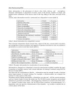
NH=NJ+HJ NUJ=NU+HJ
d
r1
d1 d d1
B
2
B2
B1 B1
r1
29.9 3 6.75 0.6 HJ204 0.012
29.5 3 5.5 0.6 HJ204E 0.009
29.9 3 7.5 0.6 HJ2204 0.013
29.5 3 6.5 0.6 HJ2204E 0.01
31.8 4 7.5 0.6 HJ304 0.017
31.1 4 6.5 0.6 HJ304E 0.014
31.8 4 8.5 0.6 HJ2304 0.018
31.1 4 7.5 0.6 HJ2304E 0.015
34.8 3 7.25 0.6 HJ205 0.015
34.5 3 6. 0.6 HJ205E 0.012
34.8 3 7.5 0.6 HJ2205 0.015
34.5 3 6.5 0.6 HJ2205E 0.013
39 4 8 1.1 HJ305 0.025
38 4 7 1.1 HJ305E 0.021
39 4 9 1.1 HJ2305 0.027
38 4 8 1.1 HJ2305E 0.024
43.6 6 10.5 1.5 HJ405 0.057
41.7 4 8.25 0.6 HJ206 0.025
41.1 4 7 0.6 HJ206E 0.017
41.7 4 8.5 0.6 HJ2206 0.025
41.1 4 7.5 0.6 HJ2206E 0.02
45.9 5 9.5 1.1 HJ306 0.039
44.9 5 8.5 1.1 HJ306E 0.035
45.9 5 11.5 1.1 HJ2306 0.043
44.9 5 9.5 1.1 HJ2306E 0.035
50.5 7 11.5 1.5 HJ406 0.08
47.6 4 8 0.6 HJ207 0.03
48 4 7 0.6 HJ207E 0.027
47.6 4 8.5 0.6 HJ2207 0.031
48 4 8.5 0.6 HJ2207E 0.031
50.8 6 11 1.1 HJ307 0.056
51 6 9.5 1.1 HJ307E 0.048
50.8 6 14 1.1 HJ2307 0.064
51 6 11 1.1 HJ2307E 0.055
59 8 13 1.5 HJ407 0.12
●L Type Loose Rib
Dimensions Bearing Mass
mm
numbers
kg
dd
1
B
1
B
2
r
1s min
1
(approx.)
B-111
1 Maximum allowable dimension for chamfer dimension r. Note: 1. This L type collar ring is used with NU type cylindrical roller bearings; in duplex
arrangements with NJ or NU type bearing numbers, they become NH type and NUJ type respectively. For bearing dimensions, allowable rotations,
and mass, please refer to pages B-98to B-103. 2. "*" indicates L type collar rings that can also be used with dimension series 22 bearings.
Dimensions Bearing Mass
mm
numbers
kg
dd
1
B
1
B
2
r
1s min
1
(approx.)
d 60∼105mm
60
65
70
75
80
80
85
90
95
100
105
84.2 9 15.5 2.1 HJ312 0.22
84.6 9 14.5 2.1 HJ312E 0.205
84.2 9 19 2.1 HJ2312 0.245
84.6 9 16 2.1 HJ2312E 0.23
91.8 10 16.5 2.1 HJ412 0.34
84.8 6 11 1.5 HJ213 0.123
84.5 6 10 1.5 HJ213E 0.111
84.8 6 11.5 1.5 HJ2213 0.126
84.5 6 10.5 1.5 HJ2213E 0.118
91 10 17 2.1 HJ313 0.28
91 10 15.5 2.1 HJ313E 0.25
91 10 20 2.1 HJ2313 0.304
91 10 18 2.1 HJ2313E 0.29
98.5 11 18 2.1 HJ413 0.42
89.6 7 12.5 1.5
*
HJ214 0.15
89.5 7 11 1.5 HJ214E 0.13
89.5 7 11.5 1.5 HJ2214E 0.138
98 10 17.5 2.1 HJ314 0.33
98 10 15.5 2.1 HJ314E 0.293
98 10 20.5 2.1 HJ2314 0.358
98 10 18.5 2.1 HJ2314E 0.35
110.5 12 20 3 HJ414 0.605
94 7 12.5 1.5
*
HJ215 0.156
94.5 7 11 1.5 HJ215E 0.141
94.5 7 11.5 1.5 HJ2215E 0.164
104.2 11 18.5 2.1 HJ315 0.4
104.6 11 16.5 2.1 HJ315E 0.35
104.2 11 21.5 2.1 HJ2315 0.432
104.6 11 19.5 2.1 HJ2315E 0.41
116.0 13 21.5 3 HJ415 0.71
101.2 8 13.5 2
*
HJ216 0.207
101.7 8 12.5 2
*
HJ216E 0.193
111.8 11 19.5 2.1 HJ316 0.47
111 11 17 2.1 HJ316E 0.405
111.8 11 23 2.1 HJ2316 0.511
111 11 20 2.1 HJ2316E 0.45
122 13 22 3 HJ416 0.78
108.2 8 14 2
*
HJ217 0.25
107.7 8 12.5 2 HJ217E 0.21
107.7 8 13 2 HJ2217E 0.216
117.5 12 20.5 3 HJ317 0.56
118.4 12 18.5 3 HJ317E 0.505
117.5 12 24 3 HJ2317 0.606
118.4 12 22 3 HJ2317E 0.55
114.2 9 15 2 HJ218 0.305
114.6 9 14 2 HJ218E 0.272
114.2 9 16 2 HJ2218 0.315
114.6 9 15 2 HJ2218E 0.308
125 12 21 3 HJ318 0.63
124.7 12 18.5 3 HJ318E 0.548
125 12 26 3 HJ2318 0.704
124.7 12 22 3 HJ2318E 0.69
121 9 15.5 2.1 HJ219 0.352
121 9 14.0 2.1 HJ219E 0.304
121 9 16.5 2.1 HJ2219 0.363
121 9 15.5 2.1 HJ2219E 0.335
132 13 22.5 3 HJ319 0.76
132.7 13 20.5 3 HJ319E 0.7
132 13 26.5 3 HJ2319 0.826
132.7 13 24.5 3 HJ2319E 0.8
128 10 17 2.1 HJ220 0.444
128 10 15 2.1 HJ220E 0.38
128 10 18 2.1 HJ2220 0.456
128 10 16 2.1 HJ2220E 0.385
140.5 13 22.5 3 HJ320 0.895
140.3 13 20.5 3 HJ320E 0.8
140.5 13 27.5 3 HJ2320 0.986
140.3 13 23.5 3 HJ2320E 0.92
135.0 10 17.5 2.1 HJ221 0.505
NH=NJ+HJ NUJ=NU+HJ
d
r1
d1 d d1
B
2
B2
B1 B1
r1
●L Type Loose Rib
L type collar ring
Dimensions Bearing Mass
mm
numbers
kg
dd
1
B
1
B
2
r
1s min
1
(approx.)
B-112
1 Maximum allowable dimension for chamfer dimension r. Note: 1. This L type collar ring is used with NU type cylindrical roller bearings; in duplex
arrangements with NJ or NU type bearing numbers, they become NH type and NUJ type respectively. For bearing dimensions, allowable rotations,
and mass, please refer to pages B-102 to B-109. 2. "*" indicates L type collar rings that can also be used with dimension series 22 bearings.
Dimensions Bearing Mass
mm
numbers
kg
dd
1
B
1
B
2
r
1s min
1
(approx.)
d 105∼200mm
105
110
120
130
140
150
150
160
170
180
190
200
NH=NJ+HJ NUJ=NU+HJ
d
r1
d1 d d1
B
2
B2
B1 B1
r1
147.0 13 22.5 3 HJ321 0.97
141.5 11 18.5 2.1 HJ222 0.615
142.1 11 17 2.1 HJ222E 0.553
141.5 11 20.5 2.1 HJ2222 0.645
142.1 11 19.5 2.1 HJ2222E 0.605
155.5 14 23 3 HJ322 1.17
156.6 14 22 3 HJ322E 1.09
155.5 14 28 3 HJ2322 1.28
156.6 14 26.5 3 HJ2322E 1.25
153 11 19 2.1 HJ224 0.715
153.9 11 17 2.1 HJ224E 0.634
153 11 22 2.1 HJ2224 0.767
153.9 11 20 2.1 HJ2224E 0.705
168.5 14 23.5 3 HJ324 1.4
169.2 14 22.5 3 HJ324E 1.28
168.5 14 28 3 HJ2324 1.53
169.2 14 26 3 HJ2324E 1.42
165.5 11 19 3 HJ226 0.84
164.7 11 17 3 HJ226E 0.684
165.5 11 25 3 HJ2226 0.953
164.7 11 21 3 HJ2226E 0.831
182 14 24 4 HJ326 1.62
183 14 23 4 HJ326E 1.53
182 14 29.5 4 HJ2326 1.8
183 14 28 4 HJ2326E 1.75
179.5 11 19 3 HJ228 1
180.2 11 18 3 HJ228E 0.929
179.5 11 25 3 HJ2228 1.14
180.2 11 23 3 HJ2228E 1.11
196 15 26 4 HJ328 1.93
196.8 15 25 4 HJ328E 1.91
196 15 33.5 4 HJ2328 2.21
196.8 15 31 4 HJ2328E 2.3
193 12 20.5 3 HJ230 1.24
194 12 19.5 3 HJ230E 1.18
193 12 26.5 3 HJ2230 1.39
194 12 24.5 3 HJ2230E 1.42
210 15 26.5 4 HJ330 2.37
211 15 25 4 HJ330E 2.25
210 15 34 4 HJ2330 2.69
211 15 31.5 4 HJ2330E 2.6
207 12 21 3 HJ232 1.48
207.8 12 20 3 HJ232E 1.34
207 12 28 3 HJ2232 1.69
206.6 12 24.5 3 HJ2232E 1.61
225 15 28 4 HJ332 2.75
223.2 15 25 4 HJ332E 2.4
225 15 37 4 HJ2332 3.16
223.2 15 32 4 HJ2332E 2.85
220.5 12 22 4 HJ234 1.7
221.4 12 20 4 HJ234E 1.51
220.5 12 29 4 HJ2234 1.93
220.2 12 24 4 HJ2234E 1.82
238 16 29.5 4 HJ334 3.25
238 16 38.5 4 HJ2334 3.71
230.5 12 22 4 HJ236 1.8
231.4 12 20 4 HJ236E 1.7
230.5 12 29 4 HJ2236 2.04
230.2 12 24 4 HJ2236E 1.91
252 17 30.5 4 HJ336 3.85
252 17 40 4 HJ2336 4.42
244.5 13 23.5 4 HJ238 2.2
245.2 13 21.5 4 HJ238E 1.94
244.5 13 31.5 4 HJ2238 2.52
244 13 26.5 4 HJ2238E 2.38
265 18 32 5 HJ338 4.45
265 18 41.5 5 HJ2338 5.05
258 14 25 4 HJ240 2.6
●L Type Loose Rib
Dimensions Bearing Mass
mm
numbers
kg
dd
1
B
1
B
2
r
1s min
1
(approx.)
B-113
1 Maximum allowable dimension for chamfer dimension r. Note: 1. This L type collar ring is used with NU type cylindrical roller bearings; in duplex
arrangements with NJ or NU type bearing numbers, they become NH type and NUJ type respectively. For bearing dimensions, allowable rotations,
and mass, please refer to pages B-108 to B-109. 2. "*" indicates L type collar rings that can also be used with dimension series 22 bearings.
d 200∼320mm
200
220
240
260
280
300
320
NH=NJ+HJ NUJ=NU+HJ
d
r1
d1 d d1
B
2
B2
B1 B1
r1
259 14 23 4 HJ240E 2.35
258 14 34 4 HJ2240 2.99
257.8 14 28 4 HJ2240E 2.86
280 18 33 5 HJ340 5
280 18 44.5 5 HJ2340 5.76
286 15 27.5 4 HJ244 3.55
307 20 36 5 HJ344 7.05
313 16 29.5 4 HJ248 4.65
335 22 39.5 5 HJ348 8.2
340 18 33 5 HJ252 6.2
362 24 43 6 HJ352 11.4
360 18 33 5 HJ256 7.39
390 26 46 6 HJ356 13.9
387 20 34.5 5 HJ260 9.14
415 21 37 5 HJ264 11.3
Boundary dimensions Basic load ratings Limiting speeds Bearing
dynamic static dynamic static
mm kN kgf rpm type NNU
cylindrical tapered
1
dD Br
s min
2
C
r
C
or
C
r
C
or
grease oil bore bore
●Multi-Row Cylindrical Roller Bearings
B-114
1 "K" indicates bearings have tapered bore with a taper ratio of 1: 12. 2 Smallest allowable dimension for chamfer dimension r.
d 25∼110mm
30
35
40
45
50
55
60
65
70
75
80
85
90
95
100
105
110
25
r
r
B
r
r
d
d
EwD
B
d
d
FW
D
Type NNU
Cylindrical bore Tapered bore
taper 1:12
Type NN
Cylindrical bore Tapered bore
taper 1:12
47 16 0.6 25.8 30.0 2,630 3,050 14,000 17,000
――
55 19 1 31.0 37.0 3,150 3,800 12,000 15,000
――
62 20 1 38.0 47.5 3,850 4,850 11,000 13,000
――
68 21 1 43.5 55.5 4,400 5,650 9,700 11,000
――
75 23 1 52.0 68.5 5,300 7,000 8,800 10,000
――
80 23 1 53.0 72.5 5,400 7,400 8,000 9,400
――
90 26 1.1 69.5 96.5 7,050 9,850 7,300 8,600
――
95 26 1.1 71.0 102 7,250 10,400 6,700 7,900
――
100 26 1.1 75.0 111 7,650 11,400 6,200 7,300
――
110 30 1.1 94.5 143 9,650 14,600 5,800 6,800
――
115 30 1.1 96.5 149 9,850 15,200 5,400 6,300
――
125 34 1.1 116 179 11,800 18,200 5,100 5,900
――
130 34 1.1 122 194 12,400 19,800 4,800 5,600
――
140 37 1.5 143 228 14,600 23,200 4,500 5,300
――
145 37 1.5 146 238 14,900 24,200 4,300 5,000
――
140 40 1.1 131 260 13,300 26,500 4,300 5,100 NNU4920 NNU4920K
150 37 1.5 153 256 15,600 26,100 4,000 4,800
――
145 40 1.1 133 268 13,500 27,400 4,100 4,800 NNU4921 NNU4921K
160 41 2 198 320 20,200 33,000 3,800 4,500
――
150 40 1.1 137 284 14,000 28,900 3,900 4,600 NNU4922 NNU4922K
170 45 2 229 375 23,300 38,000 3,600 4,300
――
●Multi-Row Cylindrical Roller Bearings
numbers Dimensions Abutment and fillet dimensions Mass
(approx.)
kg
type NN mm mm
type NNU type NN
cylindrical tapered
1
d
a
d
b
d
c
d
d
D
a
D
b
r
as
cylindrical tapered cylindrical tapered
bore bore F
w
E
w
min min max min max max min max bore bore bore bore
B-115
ra
ra
ra
ra
ra
db
da
Db
Db
daDb
da
dc
dd
Da
Pr=Fr
Por=Fr
Equivalent bearing load
dynamic
static
NN3005 NN3005K
―
41.3 29 30
―――
43 42 0.6
――
0.124 0.121
NN3006 NN3006K
―
48.5 35 36.5
―――
50 49 1
――
0.199 0.193
NN3007 NN3007K
―
55 40 41.5
―――
57 56 1
――
0.242 0.235
NN3008 NN3008K
―
61 45 47
―――
63 62 1
――
0.312 0.303
NN3009 NN3009K
―
67.5 50 52
―――
70 69 1
――
0.405 0.393
NN3010 NN3010K
―
72.5 55 57
―――
75 74 1
――
0.433 0.419
NN3011 NN3011K
―
81 61.5 63.5
―――
83.5 82 1
――
0.651 0.631
NN3012 NN3012K
―
86.1 66.5 68.5
―――
88.5 87 1
――
0.704 0.683
NN3013 NN3013K
―
91 71.5 73.5
―――
93.5 92 1
――
0.758 0.735
NN3014 NN3014K
―
100 76.5 79
―――
103.5 101 1
――
1.04 1.01
NN3015 NN3015K
―
105 81.5 84
―――
108.5 106 1
――
1.14 1.11
NN3016 NN3016K
―
113 86.5 89.5
―――
118.5 114 1
――
1.52 1.47
NN3017 NN3017K
―
118 91.5 94.5
―――
123.5 119 1
――
1.61 1.56
NN3018 NN3018K
―
127 98 101
―――
132 129 1.5
――
2.07 2.01
NN3019 NN3019K
―
132 103 106
―――
137 134 1.5
――
2.17 2.1
NN4920 NN4920K 113 129 106.5 110 111 115 133.5 133.5 131 1 1.83 1.75 1.75 1.67
NN3020 NN3020K
―
137 108 111
―――
142 139 1.5
――
2.26 2.19
NN4921 NN4921K 118 134 111.5 115 116 120 138.5 138.5 136 1 1.91 1.82 1.82 1.73
NN3021 NN3021K
―
146 114 117
―――
151 148 2
――
2.89 2.8
NN4922 NN4922K 123 139 116.5 120 121 125 143.5 143.5 141 1 1.99 1.9 1.9 1.81
NN3022 NN3022K
―
155 119 123
―――
161 157 2
――
3.69 3.56
B-116
●Multi-Row Cylindrical Roller Bearings
Boundary dimensions Basic load ratings Limiting speeds Bearing
dynamic static dynamic static
mm kN kgf rpm type NNU
cylindrical tapered
1
dD Br
s min
2
C
r
C
or
C
r
C
or
grease oil bore bore
1 "K" indicates bearings have tapered bore with a taper ratio of 1: 12. 2 Smallest allowable dimension for chamfer dimension r.
d 120∼280mm
120
130
140
150
160
170
180
190
200
220
240
260
280
r
r
B
r
r
d
d
EwD
B
d
d
FW
D
Type NNU
Cylindrical bore Tapered bore
taper 1:12
Type NN
Cylindrical bore Tapered bore
taper 1:12
165 45 1.1 183 360 18,700 37,000 3,600 4,200 NNU4924 NNU4924K
180 46 2 233 390 23,700 40,000 3,300 3,900
――
180 50 1.5 220 440 22,400 45,000 3,300 3,900 NNU4926 NNU4926K
200 52 2 284 475 29,000 48,500 3,100 3,600
――
190 50 1.5 227 470 23,100 48,000 3,000 3,600 NNU4928 NNU4928K
210 53 2 298 515 30,500 52,500 2,800 3,300
――
210 60 2 345 690 35,000 70,500 2,800 3,300 NNU4930 NNU4930K
225 56 2.1 335 585 34,000 60,000 2,600 3,100
――
220 60 2 355 740 36,500 75,500 2,600 3,100 NNU4932 NNU4932K
240 60 2.1 375 660 38,000 67,500 2,500 2,900
――
230 60 2 360 765 37,000 78,000 2,500 2,900 NNU4934 NNU4934K
260 67 2.1 440 775 45,000 79,000 2,300 2,700
――
250 69 2 460 965 46,500 98,500 2,300 2,700 NNU4936 NNU4936K
280 74 2.1 565 995 57,500 102,000 2,200 2,600
――
260 69 2 475 1,030 48,500 105,000 2,200 2,600 NNU4938 NNU4938K
290 75 2.1 580 1,040 59,000 106,000 2,000 2,400
――
280 80 2.1 555 1,180 56,500 120,000 2,100 2,400 NNU4940 NNU4940K
310 82 2.1 655 1,170 66,500 119,000 1,900 2,300
――
300 80 2.1 585 1,300 59,500 132,000 1,900 2,200 NNU4944 NNU4944K
340 90 3 815 1,480 83,000 151,000 1,700 2,100
――
320 80 2.1 610 1,410 62,500 144,000 1,700 2,000 NNU4948 NNU4948K
360 92 3 855 1,600 87,000 163,000 1,600 1,900
――
360 100 2.1 900 2,070 92,000 211,000 1,600 1,800 NNU4952 NNU4952K
400 104 4 1,060 1,990 108,000 203,000 1,500 1,700
――
380 100 2.1 925 2,200 94,500 224,000 1,400 1,700 NNU4956 NNU4956K
420 106 4 1,080 2,080 110,000 212,000 1,300 1,600
――
B-117
●Multi-Row Cylindrical Roller Bearings
numbers Dimensions Abutment and fillet dimensions Mass
(approx.)
kg
type NN mm mm
type NNU type NN
cylindrical tapered
1
d
a
d
b
d
c
d
d
D
a
D
b
r
as
cylindrical tapered cylindrical tapered
bore bore F
w
E
w
min min max min max max min max bore bore bore bore
ra
ra
ra
ra
ra
db
da
Db
Db
daDb
da
dc
dd
Da
Pr=Fr
Por=Fr
Equivalent bearing load
dynamic
static
NN4924 NN4924K 134.5 154.5 126.5 130 133 137 158.5 158.5 156.5 1 2.75 2.63 2.63 2.51
NN3024 NN3024K
―
165 129 133
―― ―
171 167 2
――
3.98 3.83
NN4926 NN4926K 146 168 138 142 144 148 172 172 170 1.5 3.69 3.52 3.52 3.35
NN3026 NN3026K
―
182 139 143
―― ―
191 183 2
――
5.92 5.71
NN4928 NN4928K 156 178 148 152 154 158 182 182 180 1.5 3.94 3.76 3.76 3.58
NN3028 NN3028K
―
192 149 153
―― ―
201 194 2
――
6.44 6.21
NN4930 NN4930K 168.5 196.5 159 164 166 171 201 201 198.5 2 6.18 5.9 5.9 5.62
NN3030 NN3030K
―
206 161 166
―― ―
214 208 2
――
7.81 7.53
NN4932 NN4932K 178.5 206.5 169 174 176 182 211 211 208.5 2 6.53 6.23 6.24 5.94
NN3032 NN3032K
―
219 171 176
―― ―
229 221 2
――
8.92 8.59
NN4934 NN4934K 188.5 216.5 179 184 186 192 221 221 218.5 2 6.87 6.55 6.56 6.24
NN3034 NN3034K
―
236 181 187
―― ―
249 238 2
――
12.6 12.2
NN4936 NN4936K
202
234 189 195 199 205 241 241 236 2 9.9 9.46 9.45 9.01
NN3036 NN3036K
―
255 191 197
―― ―
269 257 2
――
16.6 16
NN4938 NN4938K 212 244 199 205 209 215 251 251 246 2 10.4 9.94 9.93 9.47
NN3038 NN3038K
―
265 201 207
―― ―
279 267 2
――
18 17.4
NN4940 NN4940K 225 261 211 218 222 228 269 269 264 2 14.7 14 14 13.3
NN3040 NN3040K
―
282 211 218
―― ―
299 285 2
――
21.6 20.8
NN4944 NN4944K 245 281 231 238 242 248 289 289 284 2 15.9 15.2 15.2 14.5
NN3044 NN3044K
―
310 233 240
―― ―
327 313 2.5
――
29.3 28.2
NN4948 NN4948K 265 301 251 258 262 269 309 309 304 2 17.2 16.4 16.4 15.6
NN3048 NN3048K
―
330 253 261
―― ―
347 333 2.5
――
32.8 31.6
NN4952 NN4952K 292 336 271 279 288 296 349 349 339 2 29.6 28.3 28.3 27
NN3052 NN3052K
―
364 276 285
―― ―
384 367 3
――
47.4 45.8
NN4956 NN4956K 312 356 291 299 308 316 369 369 359 2 31.6 30.2 30.2 28.8
NN3056 NN3056K
―
384 296 305
―― ―
404 387 3
――
51.1 49.3
B-118
●Multi-Row Cylindrical Roller Bearings
Boundary dimensions Basic load ratings Limiting speeds Bearing
dynamic static dynamic static
mm kN kgf rpm type NNU
cylindrical tapered
1
dD Br
s min
2
C
r
C
or
C
r
C
or
grease oil bore bore
1 "K" indicates bearings have tapered bore with a taper ratio of 1: 12. 2 Smallest allowable dimension for chamfer dimension r.
d 300∼500mm
320
340
360
380
400
420
440
460
480
500
300
r
r
B
r
r
d
d
EwD
B
d
d
FW
D
Type NNU
Cylindrical bore Tapered bore
taper 1:12
Type NN
Cylindrical bore Tapered bore
taper 1:12
420 118 3 1,200 2,800 122,000 285,000 1,300 1,500 NNU4960 NNU4960K
460 118 4 1,330 2,560 135,000 261,000 1,200 1,500
――
440 118 3 1,240 2,970 126,000 305,000 1,200 1,400 NNU4964 NNU4964K
480 121 4 1,350 2,670 138,000 272,000 1,100 1,300
――
460 118 3 1,280 3,150 131,000 320,000 1,100 1,300 NNU4968 NNU4968K
520 133 5 1,620 3,200 165,000 325,000 1,100 1,300
――
480 118 3 1,290 3,250 131,000 330,000 1,100 1,300 NNU4972 NNU4972K
540 134 5 1,650 3,300 169,000 340,000 1,000 1,200
――
520 140 4 1,630 4,050 167
,
000 415,000 1,000 1,200 NNU4976 NNU4976K
560 135 5 1,690 3,450 172,000 355,000 940 1,100
――
540 140 4 1,690 4,300 172,000 435,000 940 1,100 NNU4980 NNU4980K
600 148 5 2,040 4,150 208,000 420,000 880 1,000
――
560 140 4 1,740 4,500 177,000 460,000 900 1,100 NNU4984 NNU4984K
620 150 5 2,080 4,300 212,000 440,000 840 990
――
600 160 4 2,150 5,550 219,000 565,000 850 1,000 NNU4988 NNU4988K
650 157 6 2,420 5,100 247,000 520,000 800 940
――
620 160 4 2,220 5,850 226,000 595,000 800 950 NNU4992 NNU4992K
680 163 6 2,550 5,350 260,000 545,000 750 890
――
650 170 5 2,280 5,900 233,000 600,000 770 910 NNU4996 NNU4996K
670 170 5 2,360 6,200 240,000 635,000 730 860 NNU49/500 NNU49/500K
B-119
●Multi-Row Cylindrical Roller Bearings
numbers Dimensions Abutment and fillet dimensions Mass
(approx.)
kg
type NN mm mm
type NNU type NN
cylindrical tapered
1
d
a
d
b
d
c
d
d
D
a
D
b
r
as
cylindrical tapered cylindrical tapered
bore bore F
w
E
w
min min max min max max min max bore bore bore bore
ra
ra
ra
ra
ra
db
da
Db
Db
daDb
da
dc
dd
Da
Pr=Fr
Por=Fr
Equivalent bearing load
dynamic
static
NN4960 NN4960K 339 391 313 323 335 343 407 407 394 2.5 48.6 46.4 46.4 44.2
NN3060 NN3060K
―
418 316 326
―― ―
444 421 3
――
70.8 68.6
NN4964 NN4964K 359 411 333 343 355 363 427 427 414 2.5 51.4 49.1 49 46.7
NN3064 NN3064K
―
438 336 346
―― ―
464 441 3
――
76.2 73.5
――
379
―
353 363 375 383 447
――
2.5 54.2 51.7
――
NN3068 NN3068K
―
473 360 371
―― ―
500 477 4
――
102 98.5
――
398
―
373 383 394 402 467
――
2.5 57 54.4
――
NN3072 NN3072K
―
493 380 391
―― ―
520 497 4
――
107 103
――
425
―
396 408 420 430 504
――
3 84.5 80.6
――
NN3076 NN3076K
―
512 400 411
―― ―
540 516 4
――
113 109
――
445
―
416 428 440 450 524
――
3 88.2 84.1
――
NN3080 NN3080K
―
547 420 432
―― ―
580 551 4
――
146 141
――
465
―
436 448 460 470 544
――
3 92 87.7
――
NN3084 NN3084K
―
567 440 452
―― ―
600 571 4
――
154 148
――
492
―
456 469 487 497 584
――
3 127 121
――
NN3088 NN3088K
―
596 464 477
―― ―
626 601 5
――
178 172
――
512
―
476 489 507 517 604
――
3 132 126
――
NN3092 NN3092K
―
622 484 498
―― ―
656 627 5
――
202 195
――
534
―
500 514 531 541 630
――
4 156 149
――
――
556
―
520 534 551 561 650
――
4 162 155
――
Boundary dimensions Basic load ratings
dynamic static dynamic static
mm kN kgf
dDB
1
C
1
r
s min
1
r
1s min
1
C
r
C
or
C
r
C
or
●Four-Row Cylindrical Roller Bearings
B-120
1 Minimal allowable dimension for chamfer dimension
r
or
r
1
. 2 Oil groove and oil inlet are in center of outer ring.
d 120∼200mm
130
140
145
150
160
170
180
190
200
120
C1
d
r
1
B1
D
Drawing 1
FW
r
180 92 92 2.5 2.5 400 785 40,500 80,000
180 105 105 2.5 2.5 445 855 45,500 87,000
200 104 104 2.5 2.5 490 955 49,500 97,000
210 116 116 2.5 2.5 510 1,030 52,000 105,000
210 155 155 2.5 2.5 705 1,640 71,500 168,000
225 156 156 2.5 2.5 810 1,750 82,500 178,000
220 150 150 2.5 2.5 750 1,640 76,500 168,000
230 130 130 2.5 2.5 725 1,520 73,500 155,000
230 156 156 2.5 2.5 930 2,040 95,000 208,000
250 150 150 2.5 2.5 885 1,640 90,500 167,000
220 180 180 2.5 2.5 920 2,490 93,500 254,000
230 130 130 2.5 2.5 665 1,340 68,000 136,000
230 168 168 2.5 2.5 915 2,170 93,500 222,000
240 170 170 2 2.5 980 2,290 100,000 234,000
230 120 120 2.5 2.5 620 1,520 63,000 155,000
240 156 156 2.5 2.5 905 2,170 92,500 222,000
240 160 160 2.5 2.5 905 2,180 92,000 222,000
250 168 168 2.5 2.5 970 2,220 99,000 226,000
255 180 180 2.5 2.5 1,100 2,430 112,000 247,000
260 150 150 2.5 2.5 835 1,750 85,000 179,000
260 225 225 2.5 2.5 1,310 3,150 134,000 320,000
250 156 156 2.5 2.5 895 2,180 91,500 223,000
260 168 168 2.5 2.5 1,020 2,400 104,000 244,000
265 180 180 2.5 2.5 1,090 2,510 111,000 256,000
260 168 168 2.5 2.5 980 2,600 100,000 265,000
270 170 170 2.5 2.5 1,090 2,660 111,000 272,000
270 200 200 2.5 2.5 1,260 3,100 128,000 315,000
280 200 200 2.5 2.5 1,240 2,910 126,000 297,000
270 170 170 2.5 2.5 970 2,610 99,000 266,000
280 190 190 2.5 2.5 1,190 3,150 121,000 320,000
280 200 200 2.5 2.5 1,310 3,300 134,000 335,000
●Four-Row Cylindrical Roller Bearings
Bearing
Dimensions
Drawing Mass
numbers no.
kg
F
w
(approx.)
B-121
Note: Drawing 1 represents a bearing with solid rollers and machined cage.
4R2437 137 1 8.2
4R2438 135 1 9.3
4R2628 150 1 12.1
4R2823 160 1 13.9
4R2906 166 1 18
4R2908 169 1 23.4
4R3031 168 1 19.4
4R3029 174 1 20
4R3040 174 1 24.5
4R3039 177 1 29.6
4R3224 177 1 20.2
4R3226 180 1 16.6
4R3232 179 1 23.4
4R3225 183 1 27.8
4R3426 187 1 14.2
4R3429 189 1 22.2
4R3423 190 1 22.8
4R3432 193 1 28.2
4R3425 193 1 19.3
4R3433 192 1 29.5
4R3431 196 1 44
4R3625 200 1 23.2
4R3628 202 1 29.4
4R3618 204 1 34.2
4R3820 212 1 26.9
4R3818 213 1 31.7
4R3821 212 1 37.5
4R3823 214 1
2
41.5
4R4039 222 1 28.5
4R4026 223 1 36.7
4R4037 222 1 40.5
B-122
●Four-Row Cylindrical Roller Bearings
Boundary dimensions Basic load ratings
dynamic static dynamic static
mm kN kgf
dDB
1
C
1
r
s min
1
r
1s min
1
C
r
C
or
C
r
C
or
1 Minimal allowable dimension for chamfer dimension
r
or
r
1
. 2 Oil groove and oil inlet are in center of outer ring.
3 Oil groove and oil inlet not on outer ring spacer.
d 200∼300mm
210
200
220
230
250
260
270
280
290
300
240
r1
d
FW
C1
d
r
1
B1
D
B
1
Drawing 1 Drawing 2
r
C
1
FW
r
D
290 192 192 2.5 2.5 1,290 3,150 132,000 320,000
320 216 216 3 3 1,750 3,650 179,000 375,000
290 192 192 2.5 2.5 1,230 3,350 126,000 340,000
290 192 192 2.5 2.5 1,190 3,350 122,000 340,000
300 160 160 2.5 2.5 1,000 2,590 102,000 264,000
310 192 192 2.5 2.5 1,390 3,400 141,000 350,000
310 204 204 2.5 2.5 1,420 3,750 144,000 385,000
310 215 215 2.5 2.5 1,530 3,750 156,000 380,000
310 225 225 2.5 2.5 1,480 3,950 151,000 405,000
310 265 265 2.5 2.5 1,630 4,500 167,000 460,000
320 160 160 3 3 1,190 2,550 121,000 260,000
320 210 210 2.5 2.5 1,550 3,650 158,000 370,000
330 206 206 2.5 2.5 1,520 3,800 155,000 385,000
340 260 260 3 3 2,050 5,100 209,000 520,000
330 220 220 3 3 1,490 4,150 152,000 420,000
340 220 220 3 3 1,670 4,200 170,000 425,000
360 220 220 2.5 2.5 1,760 4,050 179,000 415,000
350 220 220 3 3 1,730 4,300 176,000 440,000
370 220 220 3 3 1,760 4,450 179,000 455,000
380 280 280 3 3 2,420 6,250 247,000 635,000
380 280 280 2.5 2.5 2,580 6,850 263,000 700,000
390 220 220 3 3 1,780 4,650 181,000 475,000
390 275 275 2.5 2.5 2,290 6,250 233,000 635,000
420 280 280 4 4 2,430 6,150 248,000 630,000
410 240 240 3 3 2,240 5,550 228,000 565,000
420 300 300 3 3 2,830 7,500 288,000 765,000
400 300 300 3 3 2,480 7,500 253,000 765,000
420 240 240 3 3 2,020 5,450 206,000 555,000
420 300 300 3 3 2,720 7,600 278,000 775,000
420 300 300 3 3 2,900 7,850 295,000 800,000
●Four-Row Cylindrical Roller Bearings
Bearing
Dimensions
Drawing Mass
numbers no.
kg
F
w
(approx.)
B-123
Note:
Drawing 1 represents a bearing with solid rollers and machined cage; Drawing 2 represents a bearing with hollow rollers and pin type cage.
4R4041 226 1 42.5
4R4028 231 1 67
4R4206 236 1 39.5
4R4413 239 1 33.8
4R4419 245 1 32.8
4R4426 246 1 46.9
4R4425 247 1 49.8
4R4420 242 1 51.5
4R4416 245 1 54.9
4R4430 245 1 63.5
4R4428 245 1 46.5
4R4429 248 1 60.5
4R4614 258 1 58.6
4R4611 261 1 82.6
4R4811 270 1
2
56.8
4R4806 268 1 63.6
4R4807 274 1 79.6
4R5008 278 1 66
4R5217 292 1 76.5
4R5213 294 1 109
4R5405 299.7 2
3
105
4R5611 312 1 81.3
4R5612 312 1 105
4R5605 323 1 139
4R5806 320 1 103
4R5805 327 1 141
E-4R6014 328 1 104
E-4R6017 334 1 106
E-4R6015 334 1 125
E-4R6020 332 2 130
B-124
●Four-Row Cylindrical Roller Bearings
Boundary dimensions Basic load ratings
dynamic static dynamic static
mm kN kgf
dDB
1
C
1
r
s min
1
r
1s min
1
C
r
C
or
C
r
C
or
1 Minimal allowable dimension for chamfer dimension
r
or
r
1
. 2 Oil inlet and oil groove are in center of the outer ring; no oil groove on the side.
3 Oil inlet in space of outer ring; no oil groove. 4 One-piece inner ring.
d 300∼460mm
310
320
330
340
360
370
380
400
410
420
440
460
300
r1
d
FW
C1
d
r
1
B1
D
B
1
Drawing 1 Drawing 2
r
C
1
FW
r
D
420 320 300 3 3 2,900 7,850 295,000 800,000
460 270 270 3 3 2,510 5,350 256,000 545,000
430 240 240 3 3 2,240 5,950 228,000 605,000
440 240 230 3 3 2,290 6,050 234,000 615,000
450 240 240 3 3 2,370 6,150 242,000 630,000
460 340 340 3 3 3,400 9,450 345,000 960,000
470 350 350 3 3 4,150 10,900 425,000 1,110,000
440 200 200 3 3 1,820 4,850 186,000 495,000
460 340 340 4 4 3,250 8,850 330,000 905,000
480 370 350 5 5 3,450 9,650 350,000 985,000
490 300 300 4 4 3,350 8,300 340,000 845,000
510 400 400 5 5 4,250 11,500 435,000 1,170,000
480 230 230 5 5 2,100 6,250 214,000 635,000
520 400 400 5 5 4,650 13,500 475,000 1,370,000
520 280 280 4 4 3,400 9,150 350,000 935,000
520 300 300 4 4 3,550 9,600 360,000 980,000
540 400 400 4 4 5,200 15,200 530,000 1,550,000
560 400 400 5 5 4,250 11,800 430,000 1,210,000
560 410 410 4 4 5,750 17,000 585,000 1,730,000
546 400 400 5 5 4,200 12,700 430,000 1,290,000
560 280 280 4 4 3,150 8,750 320,000 895,000
580 230 230 4 4 2,430 6,250 248,000 635,000
620 400 400 5 5 5,000 13,400 510,000 1,360,000
620 450 450 5 5 6,450 18,700 660,000 1,910,000
620 400 400 4 4 5,350 16,700 545,000 1,700,000
620 400 400 4 4 4,950 15,000 505,000 1,530,000
650 470 470 5 5 7,150 20,600 730,000 2,100,000
●Four-Row Cylindrical Roller Bearings
Bearing
Dimensions
Drawing Mass
numbers no.
kg
F
w
(approx.)
B-125
Note:
Drawing 1 represents a bearing with solid rollers and machined cage; Drawing 2 represents a bearing with hollow rollers and pin type cage.
E-4R6018 332 2 136
E-4R6019 344 1 162
E-4R6202 344.5 1 108
E-4R6414 351 1 106
E-4R6411 358 1 125
E-4R6412 360 1 178
E-4R6406 361.7 2 212
E-4R6603 360 1
2
83.6
E-4R6605 365 1 181
E-4R6811 378 1 198
E-4R6804 377 1 187
E-4R7203 397 1
2
262
E-4R7405 400 1 106
E-4R7404 409 1 273
E-4R7605 417 1 174
E-4R7607 416 2
3
210
E-4R7604 422 2
3
325
E-4R8007 446 1 303
E-4R8010 445 2 349
E-4R8201 444 1
2
256
E-4R8403 457 1 189
E-4R8404 466 1 181
E-4R8401 478 1 410
E-4R8801 487 2 437
E-4R9211 502 2
34
383
E-4R9209 502 1 341
E-4R9216 509 2 540
B-126
●Four-Row Cylindrical Roller Bearings
Boundary dimensions Basic load ratings
dynamic static dynamic static
mm kN kgf
dDB
1
C
1
r
s min
1
r
1s min
1
C
r
C
or
C
r
C
or
1 Minimal allowable dimension for chamfer dimension
r
or
r
1
. 2 Oil inlet and oil groove are in center of the outer ring; no oil groove on the side.
3 Oil inlet in space of outer ring; no oil groove.
d 480∼690mm
480
500
510
520
530
550
560
570
600
610
650
r1
d
FW
C1
d
r
1
B1
D
B
1
Drawing 1 Drawing 2
r
C
1
FW
r
D
690
660
650 420 420 5 5 5,950 18,100 605,000 1,840,000
650 450 450 9.5X20
°
5 7,100 21,600 720,000 2,200,000
680 500 500 6 6 7,950 24,000 810,000 2,450,000
680 420 405 5 5 7,100 22,900 725,000 2,340,000
690 470 470 5 5 7,650 22,500 780,000 2,290,000
690 510 510 5 5 7,750 24,600 790,000 2,500,000
700 515 515 5 5 7,900 24,100 805,000 2,450,000
710 480 480 6 6 8,650 24,700 880,000 2,520,000
720 530 530 5 5 8,250 25,000 840,000 2,550,000
670 320 320 5 5 4,550 13,500 465,000 1,380,000
700 540 540 6 6 8,300 25,000 845,000 2,550,000
700 540 540 6 6 8,200 25,500 835,000 2,600,000
735 535 535 5 5 9,000 26,600 915,000 2,710,000
700 540 540 6 6 7,850 25,400 800,000 2,590,000
760 520 520 6 6 9,150 26,700 935,000 2,730,000
780 570 570 6 6 10,300 29,100 1,050,000 2,970,000
800 520 520 6 6 9,450 27,000 965,000 2,750,000
680 360 360 3 3 4,650 16,500 475,000 1,680,000
815 594 594 6 6 11,800 34,500 1,200,000 3,500,000
820 575 575 12X20
°
6 10,000 31,500 1,020,000 3,200,000
870 540 540 7.5 7.5 10,600 29,600 1,090,000 3,000,000
870 640 640 7.5 7.5 13,600 40,500 1,390,000 4,150,000
870 660 660 9.5 7.5 12,600 40,000 1,280,000 4,100,000
920 670 670 7.5 4 14,600 46,000 1,490,000 4,700,000
920 690 690 7.5 7.5 14,300 46,500 1,460,000 4,750,000
820 440 440 5 4 7,300 27,800 745,000 2,840,000
980 715 715 7.5 7.5 16,800 54,500 1,720,000 5,550,000
●Four-Row Cylindrical Roller Bearings
Bearing
Dimensions
Drawing Mass
numbers no.
kg
F
w
(approx.)
B-127
4 One-piece inner ring. Note:
Drawing 1 represents a bearing with solid rollers and machined cage; Drawing 2 represents a bearing with hollow
rollers and pin type cage.
E-4R9607 523 2
4
369
E-4R9609 525 2
4
395
E-4R9604 532 2 640
E-4R10010 550 2
3
495
E-4R10016 547 2 590
E-4R10006 552 2 640
E-4R10011 554 2 680
E-4R10008 556 2 675
E-4R10015 568 2 780
E-4R10201 554 2
4
335
E-4R10202 558 2 689
E-4R10403 564 2 658
E-4R10402 574.5 2 740
E-4R10603 574 2 626
E-4R10601 590 2 800
E-4R10602 601 2 1 010
E-4R11001 622 2 965
E-4R11202 590 1 265
E-4R11402 628 2 1 040
E-4R12003 655 2 980
E-4R12002 672 2 1 150
E-4R12001 672 2 1 330
E-4R12202 680 2
2
1 400
E-4R13005 723 2 1 500
E-4R13003 723 2 1 550
E-4R13201 702 2 580
E-4R13802 767.5 2 1 850
B-128
●Four-Row Cylindrical Roller Bearings
Boundary dimensions Basic load ratings
dynamic static dynamic static
mm kN kgf
dDB
1
C
1
r
s min
1
r
1s min
1
C
r
C
or
C
r
C
or
1 Minimal allowable dimension for chamfer dimension r or r
1
. 2 Inner ring is divided into four. 3 Oil mist nozzles are attached.
4 Oil inlet in space of outer ring; no oil groove.
d 700∼1 200mm
700
710
725
750
760
800
820
840
850
860
900
920
1000
r1
d
FW
C1
d
r
1
B1
D
B
1
Drawing 1 Drawing 2
r
C
1
FW
r
D
1030
1200
930 620 620 15X20
°
6 12,900 43,000 1,320,000 4,400,000
1,000 715 715 9.5 6 16,800 54,500 1,710,000 5,550,000
1,000 700 700 6 6 15,900 53,500 1,620,000 5,450,000
1,050 745 720 7.5 7.5 17,600 58,000 1,790,000 5,900,000
1,090 745 720 7.5 7.5 19,100 60,500 1,950,000 6,150,000
1,030 750 750 7.5 7.5 17,300 59,500 1,760,000 6,050,000
1,080 805 790 6 6 18,700 61,000 1,900,000 6,250,000
1,100 745 720 7.5 7.5 19,100 60,500 1,950,000 6,150,000
1,080 700 700 7.5 7.5 16,500 55,000 1,680,000 5,600,000
1,080 750 750 6 6 17,300 59,000 1,760,000 6,000,000
1,130 800 800 7.5 7.5 19,600 66,500 2,000,000 6,800,000
1,130 825 800 7.5 7.5 19,600 66,500 2,000,000 6,800,000
1,160 840 840 7.5 7.5 21,600 71,000 2,200,000 7,250,000
1,160 840 840 5 7.5 21,600 71,000 2,200,000 7,250,000
1,150 650 650 9.5 9.5 15,700 51,000 1,610,000 5,200,000
1,150 800 800 6 6 19,700 71,000 2,010,000 7,250,000
1,180 650 650 7.5 7.5 16,400 51,500 1,670,000 5,250,000
1,180 850 850 9.5 9.5 24,100 78,500 2,460,000 8,000,000
1,160 735 710 6 6 17,800 62,500 1,810,000 6,400,000
1,230 895 870 7.5 7.5 24,700 88,000 2,520,000 9,000,000
1,280 865 850 7.5 7.5 26,200 88,500 2,670,000 9,000,000
1,310 880 880 9.5 9.5 23,400 88,500 2,380,000 9,000,000
1,360 800 800 7.5 7.5 25,000 85,000 2,550,000 8,650,000
1,380 850 850 7.5 7.5 24,400 89,000 2,490,000 9,100,000
1,590 1,050 1,050 7.5 7.5 36,000 133,000 3,650,000 13,600,000
●Four-Row Cylindrical Roller Bearings
Bearing
Dimensions
Drawing Mass
numbers no.
kg
F
w
(approx.)
B-129
Note:
Drawing 2 represents a bearing with hollow rollers and pin type cage.
E-4R14003 763 2 1 200
E-4R14205 787.5 2
2
1 900
E-4R14501 796 2 1 730
E-4R15001 830 2
3
2 180
E-4R15002 845 2
3
2 530
E-4R15204 828 2
3
2 000
E-4R15207 845 2
3
2 550
E-4R15203 855 2
3
2 560
E-4R16004 870 2 1 950
E-4R16005 880 2 2 090
E-4R16406 903 2
3
2 450
E-4R16405 903 2 2 520
E-4R16403 910 2 2 930
E-4R16801 920 2 2 840
E-4R17001 941 2 1 980
E-4R17003 930 2 2 430
E-4R17004 945 2 2 270
E-4R17002 928 2 2 970
E-4R17201 940 2 2 310
E-4R18001 985 2
3
3 250
E-4R18401 1 015 2 3 560
E-4R20001 1 080 2 3 260
E-4R20002 1 090 2 3 530
E-4R20601 1 124 2 3 800
E-4R24002 1 295 2
2
6 220
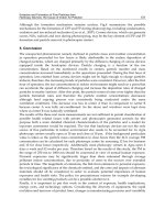
1.
Types, design features, and characteristics
Tapered roller bearings are designed so that the center
lines of the raceways and rollers all converge at a single
point as shown in Diagram 1.
Due to this design feature, rollers move along the center of
the raceway surfaces. The tapered rollers are guided by the
compound force of the inner and outer raceway surfaces
which keep them pressed up against the large rib on the
inner ring. A large variety of these bearings, including single,
double, and four row arrangements, are in use both in metric
and inch system sizes.
Table 1 lists the various types of tapered roller bearings
and their characteristics.
B-131
Type Characteristics
Single row tapered
roller bearings
(2) In addition to level type, there are also medium contact angle and large contact angle types, and the contact
angle code C and D, respectively, is appended to the basic numbers of the latter two types.
(3) Subunits
Tapered roller bearings can be disassembled into parts ― the inner ring, rollers, and cage (collectively
known as the "cone") ― and the outer ring (known as the "cup"). These are the bearing’s "subunits". Subunit
dimensions are standardized under ISO or ABMA standards, and unified subunits are interchangeable within
each dimensional standard. However, high precision grade bearings are generally not interchangeable, and
these subunits must be used by assembling only subunits with identical manufacturing numbers.
Aside from any cautionary notes that may appear, the single row tapered roller bearings listed in the
dimension tables have subunits standardized for both metric and inch systems (including J series). (Refer to
Diagram 2)
Diagram 2.
E
2α
Subunit dimensions
E : Outer ring (cup)
nominal small-end diameter
α : Nominal contact angle
*Dimension series previously not covered by 3XX are regulated under JIS B 1512;
dimensions previously missing from 3XX will henceforth use the bearing number.
Dimension series
Basic
number
Regulations
Metric system Inch system
Example, 30210
*T2EE040
¡JIS B 1512
¡ISO 355
¡ABMA
(includes metric J-series)
Inner ring no. / outer ring no.
("J" appears at the beginning of the
basic number in the case of J-series.)
(1) There are both metric and inch system dimension series, and they have been standardized as shown in the
following table.
Table 1 Tapered roller bearing types and characteristics
Diagram 1.
Single row tapered roller bearings Double row tapered roller bearings Four row tapered roller bearings
●Tapered Roller Bearings
B-132
Type Characteristics
(5) These bearings are constructed to have a high capacity for radial loads,
axial loads, and combined loads. The larger the contact angle, the
greater the axial load capacity becomes. When a pure radial load is
placed on the bearings, an induced load in the axial direction is also
generated, and so these bearings are generally used in pairs arranged
face to face.
(6) When used in pairs, proper internal clearances and preload can be set by
adjusting the distance between the two bearings' inner and outer rings.
(7) Inner and outer rings are separable, enabling them to be installed
individually with the desired interference fit.
(8) Tapered roller bearings are also manufactured with flanges attached to
the outer rings. For more details, contact
NTN Engineering. (Refer to
Diagram 3)
Single row tapered
roller bearings
(1) Outward facing types (using double row outer rings) and inward facing
types (using double row inner rings) are both available, and they have
been adjusted so that each type's internal clearance values are fixed.
Therefore, only parts with identical manufacturing numbers can be
used and they must be assembled according to their code numbers.
(Refer to Diagram 4)
(2) The axial internal clearances for double and duplex bearings are
listed in Table 8 on pages A-58, 59.
(3) Pairs of duplex single row tapered roller bearings are also
manufactured. For more details, contact NTN Engineering.
Double row tapered
roller bearings
(1) As shown in Diagram 5, four row tapered roller bearings are
constructed of two double row inner rings and two double row outer
rings.
(2) Bearings wear life is greatly improved through the use of induction
hardening and, for large-sized bearings, hollow rollers and pin type
cages.
(3) Used primarily where heavy load capacity is important, and in the
roller necks of rolling mills.
Four row tapered
roller bearings
Furthermore, although not listed in the dimension tables, ET type bearings are also manufactured for some extra
small bearing sizes. For details, consult NTN Engineering.
(4) Concerning ET and 4T
Types ET and 4T tapered roller bearings are made of high-purity case hardened steel and are manufactured with
a special heat treatment developed by
NTN. As a result, wear life and reliability have been improved to where life
coefficient, a2, values can be applied as follows:
4T tapered roller bearings: a2 =1.4
ET tapered roller bearings: a2 =1.9
Diagram 4.
Inward facing Outward facing
Diagram 3.
Diagram 5.
Table 1 (continued)
●Tapered Roller Bearings
B-133
2. Standard cage type
In general, pressed cages are used in tapered roller
bearings.
However, for large sized bearings, machined or pin type
cages are also used; and for small sized bearings, molded
resin cages are also used.
3. Allowable misalignment
Single row and
back-to-back arrangement: ………0.0005rad(1.5')
Face-to-face: …………………………0.001rad (3.5')
In situations where large displacement is necessary,
please consult
NTN Engineering.