Deploying RFID Challenges Solutions and Open Issues Part 8 potx
Bạn đang xem bản rút gọn của tài liệu. Xem và tải ngay bản đầy đủ của tài liệu tại đây (1.53 MB, 30 trang )
Mine Planning Using RFID
197
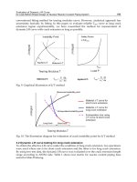
Static information is the placement of shovel, silos, belts, railway, and inscriptions.
Dynamic information is placement of trucks, state of the shovel, number of empty and
loaded trucks, utilization of the shovel, time of the trip, filling of the silos, and load of the
belts.
Аt first, static information must be constructed on a dispatcher’s screen (table 5).
Information Details Accuracy
Scheme of the mine no required ± 10 m
Places of loading no required ± 10 m
Places of unloading no required ± 10 m
Network of existing faces no required ± 10 m
Network of abandoned faces no required ± 10 m
Network of communications no required ± 10 m
Transport network no required ± 10 m
Placement of the stationary machines no required ± 10 m
Various tables standard standard
Various inscriptions standard standard
Table 5. Static information for a dispatcher’s screen
Then dynamic information about current time, output of the face, current plan’s execution,
pre-recognition of future accidents, and support of operative decisions in case of accidents is
presented on a screen in real-time mode (table 6).
Information Regularity Reflection
State of a face Every hour Color of a face
Distribution of mobile objects Every 15 minutes Placement on the network
Output of a face Every hour Current data
Time of a working cycle Each working cycle Data
Output of the part of the mine Each shift Data
Fullness of every bin Every 15 minutes Full part of bin
State of the transport machine Each trip Color of a machine
Table 6. Dynamic information for visualization of current mining
Information is changed on a dispatcher’s screen by introduction of global variables (by tags).
Connection of medium sources with virtual reflection of mining is realized using OLE for
Process Control (OPC).
The main rule for visualization is that the information must be enough to make a decision
about improvement of current mining. For example, a decision-maker can compare the
activity in various places of the mine.
Watching current mining information, a dispatcher can step and call the concrete persons,
such as a team’s leader to clear the matter up. The SCADA-system recognizes pre-accident
situations in good time and notifies about beginning violations in normal work of the mine.
If a random accident takes place, the SCADA-system produces recommendations to a
dispatcher, who can prevent a deterioration of the situation , e.g. localize a random fire in
various places of the mine.
Deploying RFID – Challenges, Solutions, and Open Issues
198
As well as current information, the SCADA-system keeps detailed information about past
mining, such as utilization of a mine machine. Comparison of current information with
former information can improve the current mining.
Using this system, the information about total working time, expenses of energy, total
output, utilization of mobile objects, and utilization of bins can be acquired for managers of
the mine.
10. Mining execution system
The system is geared to control execution of shift planning and prepare information for the
standard “Mine’s Resources Planning “.
Sometimes mine equipment units have failures. Breakages lead to random refusals of a total
technological chain.
Mining Execution System (MES) redistributes the faces and mine machines to ensure the
same output of mine. The standard needs current information about mining (table 7).
Information Regularity Effect for mine planning
Output of a face All the time Contribution of a face to the mine’s output
State of a face All the time Re-distribution of mining’s places
Working time of a face All the time Fulfillment of a face’s plan
State of a machine All the time Control of mining
Working time of a machine All the time Planning of maintenance
Placement of a machine All the time Planning of mining
Placement of miners All the time Planning of miners’ distribution
Working time of a miner All the time Evaluation of miner’s use
Fulfillment of a mine’s plan All the time Evaluation of plan’s fulfillment
Real time All the time Evaluation of the shift’s time
Table 7. Information for “Mining Execution System”
Using this information, a mine dispatcher can determine how to maintain output during of
unpredictable situations.
11. Suitability of RFID for mine planning
Optical character recognition needs comparison with a model. Random forms of objects,
such as surge pile of rock mass make this impossible for mining. Infrared identification is
not applicable for mining, because there is limited potential for a changing environment,
requires the line of sight between a transmitter and receiver of information, needs
comparison with a pattern. Bar coding has no protection to soiling and can not be attached
by new information.
As a rule, voice sources of information are in use for mine planning. Voice sources are non-
exact and non-reliable for mine planning.
Mobile data mediums on the basis of RFID produce many opportunities for mine planning.
RFID- system can work under the harsh mine environment and does not require the light-of
–sight between a transponder and a writer. Active transponders can be read at great
distances. It is an obvious use of an RFID- system for identification and positioning of
mobile objects.
Mine Planning Using RFID
199
Some mines introduce RFID to identify miners (RFID for Mining, 2008), like identification of
goods in commerce. Many transponders can be read at once. Nobody can avoid being
identifies before work. RFID-systems present the data in real time. It is impossible to forge
information inside a transponder.
The possibility exists to add information and use machines to deliver data about working
places in real time. Active transponders for mine applications may be smart. RFID- systems
have no moving parts and do not require regular maintenance.
However, all miners must be informed in case of an accident. RFID may not be used to
transfer accident information. The special design of RFID- system for a metal, dirty, and
dusty environment is necessary. A mine must be equipped with an information network.
Underground mines for coal mining require special permission to use RFID-system in an
explosion-dangerous environment.
12. Towards intellectual mining
Deposits of useful minerals that were easily accessible for traditional mining are exhausted
already. Historically, an underground mine is dangerous and unpleasant for miners. At
present, the average depth of mines is 1200 meters. The deeper a mine is, the worse and
more dangerous miners’ work is and the more expensive miners’ work is. The high
temperature of the Earth’s centre raises the temperature of the underground mine and it will
be impossible to work.
It is too hard to co-ordinate underground mining actions in space and time. There are idle
times of underground equipment owing to inadequate information about current mining.
Employers waste a lot of money transporting miners for underground work.
The long-term dream of mining engineers is to be able to mine without underground
miners. The main idea is – the control of underground machines from the surface (Fig. 15).
Fig. 15. Underground mining without underground drivers: 1-drilling machine; 2- loading—
haulage-dumping machine; 3- shotcreting machine; 4- charging machine; 5- drivers’ box
Deploying RFID – Challenges, Solutions, and Open Issues
200
A console for remote control is situated in front of a working place. One is connected via an
underground information network with the driver’s box on surface. Mobile mine machines
move along a guideline, which is placed in roadways. A driver observes a working place as
if he is on a machine and transfers control commands to the machine. Each of the mine
machines is equipped with an on-board receiver.
A broadband information network is the backbone of future mining. Such a network must
transfer video, audio, and data information from distributed working places to the surface
and back.
A machine in intellectual mine can adapt itself to changing working conditions: to change
positions of working heads, direction of movement, step size of a roof support, and speed of
a roof support. Such opportunities will make it possible to avoid some geological hazards,
avoid dangerous rock pressure manifestations, stabilize the quality of mining, and increase
the utilization of machinery. Existing information networks for voice exchange is not
available for intellectual mining because the control of an autonomous machine in real-time
needs a broad transmission band for video information.
Information network for a future mine could be used not only for remote control of
underground machines, but also for mine planning using RFID.
As the long-term, an RFID-system for mining on other planets without direct visibility of a
working place can be created.
13. System approach to use RFID for mine planning
The main idea of system approach consists of the creation of elements for the future system
using step-by-step development. Each element will be included in a future system later
without changes.
An RFID-system will be included in future mining that is based on control without direct
visibility. How to transfer current information about mining to management of the mine?
Many distributed working places are moving all the time during mining.
The existing information network in a mine was created for telephonic communication only
which has a narrow communication band. Probably, transmission of data information via
such a network will be incorrect for future mine planning.
A distributed information network for a future mine must transfer video information in
real time mode to a remote driver. That is why one must connect moving transmitters with
stationary receivers and be broad- band. Later, the network for future mining will be used
for transferring information from on-board transponders without additional expense.
14. Need for research on the way to mine planning using RFID
It is necessary to test the RFID- system for the harsh mine environment that is metal, dirty,
dusty, and damp.
An on-board RFID-writer for a suitable mine machine must be selected. One should have
input for a sensor and output for the transponder. Existing telephonic network must be
tested for suitability to transfer data information from the transponder.
The influence of random electromagnetic interference on RFID-system must be evaluated.
Placement of RFID-writer and RFID-transponder on a mine machine must be carefully
chosen. The packages must be developed for each stage of mine planning. A human-
machine interface must be developed for the visualization of current mining.
Mine Planning Using RFID
201
15. Conclusion
Mining has many peculiarities to get reliable information for mine planning. Environment
for a data medium is humid, dirty, and dusty. Mine machines are metal. Working places are
distributed in a space and move all the time. At present, RFID is used for identification of
miners only, like identification of moving goods using EPC.
The connection of a sensor on a mobile object allows an RFID-writer to develop new
potential for RFID-applications in mine planning.
Such a mobile data medium allows the gathering of various information: current reports about
an extraction in various places of a deposit, placement of mobile objects during mining in real
time, avoidance of non-permitted access to control, acquisition of full information about
current mining, warning about emergency situations, and etc. An RFID-system can be used to
visualize the placement of machines along roadways; to monitor miners with personal
transponders; to prevent non-permitted control of machines; to give priority control of
machines; to evaluate productivity of both machines and mining areas; to evaluate fuel
consumption and machine resources. This information can be used for management of the
mine.
16. Acknowledgment
This work is supported by the Russian Foundation of Basic Researches, grant № 10-08-
01211-а “Modeling of mining on deep mines” and the State Program “Joining of Science and
High Education in Russia for 2002-2006”, grant № U0043/995 “Preparation of experts in
information technologies for Kuzbass region”. Many thanks to my old friends Prof. J.Sturgul
and his wife Alison (Australia) for the thorough correction of English text.
17. References
Konyukh, V.; Tchaikovsky, E.& Rubtzova, E. (1988). Ways for the measurement of a
LHD- bucket filling during extraction of ore out of dangerous places. Physics-
technical problems of mining, No.2 (March-April1988), pp.67-73, ISSN 0015-3273 (in
Russ.).
Konyukh, V. (2005). Achievements in industrial automation and their possible applications
for underground mining, Proceedings of 14-th Int. Symp. on Mine Planning
and Equipment Selection (MPES2005), pp. 645-661, ISBN 093-0-9968-835-9, Canada,
Calgary, Sept. 16-20, 2005
Konyukh, V. (2010). Simulation of mining in the future, Proceedings of IASTED International
Conference on Control, Diagnostics, and Automation (ACIT 2010), рр.1-6, ISBN 078-0-
88986-842-7, Novosibirsk, Russia, June 15-18, 2010
Krieg, G. (2005). Kanban-Controlled Manufacturing Systems, Springer-Verlag, ISBN 3-540-
22999-X, Berlin Heidelberg
Wilma’s, C.
(2009). Applying active RFID in mining, In: Instrumentation and Control, 1 Jan.
2009, Available from www.instrumentation.co.za/papers/C9205.pdf
Spadavecchia, O. ( 2007). RFID technology searching for more mining applications, In:
Mining weekly, 13th April 2007, Available from www.miningweekly.com
RFID for Mining (2008). Available from www.falkensecurenetworks.com
Deploying RFID – Challenges, Solutions, and Open Issues
202
Sturgul, J. (1995). Simulation and animation: come of age in mining , In: Engineering and
Mining Journal, October 1995, pp.17-19.
0
The Applicability of RFID for Indoor Localization
Apostolia Papapostolou, Hakima Chaouchi
Telecom & Management Sudparis
France
1. Introduction
Although RFID has a relatively long history of more than 50 years in the field of wireless
communications, only the last decade it has received a considerable attention for becoming
a useful general purpose technology. Actually, RFID was initially developed as an automatic
identification system consisting of two basic component types, a reader and a tag (Want, 2006).
The reader is able to read the IDs of tags in its vicinity by running a simple link-layer protocol
over the wireless channel. RFID tags can be either active or passive depending on whether
they are powered by battery or not, respectively. Passive tags are prevalent in supply chain
management as they do not need a battery to operate. This makes their lifetime large and
cost negligible. The low cost of passive tags, the non-LOS requirement, the simultaneous
reading of multiple tags and the reduced sensitivity regarding user orientation motivated the
academia and industry for exploring its potentials in more intelligent applications Baudin &
Rao (2005).
This chapter studies whether an RFID deployment can be applied for the purpose of indoor
localization. It is widely accepted that location awareness is an indispensable component
of the future ubiquitous and mobile networks and therefore efficient location systems are
mandatory for the success of the upcoming era of pervasive computing. However, while
determining the location of objects in outdoor environments has been extensively studied and
addressed with technologies such as the Global Positioning System (GPS) (Wellenhoff et al.,
1997), the localization problem for indoor radio propagation environments is recognized to be
very challenging, mainly due to the presence of severe multi-path and shadow fading. The key
properties of RFID motivated the research over RFID-based positioning schemes. Correlating
tag IDs with their location coordinates is the principle concept for their realization.
Though RFID offers promising benefits for accurate and fast tracking, there are some
technology challenges that need to be addressed and overcome in order to fully exploit its
potential. Indeed, the main shortcoming of RFID is considered the interference problem
among its components, mainly due to the limited capabilities of the passive tags and the
inability of communication between readers (GP & SW, 2008). There are three main types
of RFID interference. The first one is due to the responses of multiple tags to a single reader’s
query, the second is related to the queries of multiple readers to a single tag and finally, the
third is due to the low signal power of weak tag responses compared to the stronger neighbor
readers’ transmissions. The first type affects the time response of the system, whereas the
other two reduce the positioning accuracy. In addition, interference from non-conductive
materials such as metal or glass imposes one more concern regarding the appropriateness of
RFID for widespread deployment.
11
2 Will-be-set-by-IN-TECH
In this chapter, deploying cheap RFID passive tags within an indoor environment in order
to determine the location of users with reader-enabled mobile terminals is proposed. The
rationale behind selecting such configuration is mainly due to the low cost of passive
tags, making their massive deployment a cost-effective solution. Moreover, next generation
mobile terminals are anticipated to support RFID reading capabilities for accessing innovative
tag-identifiable services through the RFID network. Three popular positioning algorithms are
compared. The reason of their selection is because they can be all easily implemented on either
the mobile or a central engine but they differ in their processing requirements. This chapter
also studies the impact of several system design parameters such as the positioning algorithm,
the tag deployment and the read range, on the accuracy and time efficiency objectives. Finally,
mechanisms for dealing with these problems are also discussed.
The rest of this chapter is organized as follows: section 2 provides essential background for
indoor localization and popular RFID positioning systems. In section 3 we explain the main
shortcomings of RFID regarding localization which was our main motivation for conducting
this study. In section 4 the conceptual framework of a RFID-based positioning system is
described and section 5 provides simulation-based analysis results. Finally, in section 6 we
give our main conclusions.
2. Background and related work
This section provides an overview of the indoor localization problem and a literature review
in RFID indoor positioning systems.
2.1 Indoor localization
The localization problem is defined as the process of determining the current position of a user
or an object within a specific region, indoor or outdoor. Position can be expressed in several
ways depending on the application requirements or the positioning system specifications.
Localization using radio signals has attracted considerable attention in the fields of
telecommunication and navigation. The most well known positioning system is the Global
Positioning System (GPS) (Wellenhoff et al., 1997), which is satellite-based and very successful
for tracking users in outdoor environments. However, the inability of satellite signals to
penetrate buildings causes the complete failure of GPS in indoor environments. The indoor
radio propagation channel is characterized as site specific, exhibiting severe multi-path effects
and low probability of line-of-sight (LOS) signal propagation between the transmitter and the
receiver (Pahlavan & Levesque, 2005), making accurate indoor positioning very challenging.
For indoor location sensing a number of wireless technologies have been proposed, such as
infrared (Want et al., 1992), ultrasound (Priyantha et al., 2000), WiFi (Bahl & Padmanabhan,
2000), (Youssef & Agrawala, 2005), (King et al., 2006), (Papapostolou & Chaouchi, 2009a),
(Ubisense, n.d.), UltraWideBand (UWB) (Ingram et al., 2004), and more recently RFID
(Hightower et al., 2000), LANDMARC, (Ni et al., 2004), (Wang et al., 2007), (Papapostolou
& Chaouchi, 2009b).
Localization techniques, in general, utilize metrics of the Received Radio Signals (RRSs).
The most traditional received signal metrics are based on angle of arrival (AOA), time of
arrival (TOA), time difference of arrival (TDOA) measurements or received signal strength
(RSS) measurements from several Reference Points (RPs). The reported signal metrics are
then processed by the positioning algorithm for estimating the unknown location of the
receiver, which is finally utilized by the application. The accuracy of the signal metrics and
the complexity of the positioning algorithm define the accuracy of the estimated location.
204
Deploying RFID – Challenges, Solutions, and Open Issues
The Applicability of RFID for Indoor Localization 3
Depending on how the signal metrics are utilized by the positioning algorithm, we can
identify three major families of localization techniques (Hightower & Borriello, 2001), namely
triangulation, scene analysis and proximity.
2.1.1 Triangulation
Triangulation methods are based on the geometric properties of a triangle to estimate the
receiver’s location. Depending on the type of radio signal measurements, triangulation can be
further subdivided into multi-lateration and angulation method. In multi-lateration techniques,
TOA, TDOA or RSS measurements from multiple RPs are converted to distance estimations
with the help of a radio propagation model. Examples of such positioning systems include
GPS (Wellenhoff et al., 1997), the Cricket Location System (Priyantha et al., 2000), and the
SpotON Ad Hoc Location (Hightower et al., 2000). However, models for indoor localization
applications must account for the effects of harsh indoor wireless channel behavior on the
characteristics of the metrics at the receiving side, characteristics that affect indoor localization
applications in ways that are very different from how they affect indoor telecommunication
applications. In angulation techniques, AOA measurements with the help of specific antenna
designs or hardware equipment are used for inferring the receiver’s position. TheUbisense
(Ubisense, n.d.) is an example of AOA-based location sensing system. The increased
complexity and the hardware requirement are the main hindrances for the wide success of
such systems.
2.1.2 Scene analysis/fingerprinting
Scene analysis or fingerprinting methods require an offline phase for learning the RRS behavior
within a specific area under study. This signal information is then stored in a database
called Radio Map. During the real-time localization phase, the receiver’s unknown location
is inferred based on the similarity between the Radio Map entries and the real-time RSS
measurements. RADAR (Bahl & Padmanabhan, 2000), HORUS (Youssef & Agrawala, 2005),
COMPASS (King et al., 2006) and WIFE (Papapostolou & Chaouchi, 2009b) follow this
approach. The main shortcoming of scene analysis methods is that they are susceptible to
uncontrollable and frequent environmental changes which may cause inconsistency of the
signal behavior between the training phase and the time of the actual location determination
phase.
2.1.3 Proximity
Finally, proximity methods are based on the detection of objects with known location. This can
be done with the aid of sensors such as in Touch MOUSE (Hinckley & Sinclair, 1999), or based
on topology and connectivity information such as in the Active Badge Location System (Want
et al., 1992), or finally with the aid of an automatic identification system, such as credit card
point of cell terminals. Such techniques are simple but usually suffer from limited accuracy.
2.2 RFID positioning systems
RFID positioning systems can be broadly divided into two classes: tag and reader localization,
depending on the RFID component type of the target.
In tag localization schemes, readers and possibly tags are deployed as reference points within
the area of interest and a positioning technique is applied for estimating the location of
a tag. SpotON (Hightower et al., 2000) uses RSS measurements to estimate the distance
between a target tag and at least three readers and then applies trilateration on the estimated
205
The Applicability of RFID for Indoor Localization
4 Will-be-set-by-IN-TECH
System Target Deployment Approach Accuracy
Hightower et al. (2000) Tag Readers RSS trilateration 3 m
Ni et al. (2004) Tag Readers & Tags RSS Scene Analysis 1-2m
Wang et al. (2007) Tag Readers & Tags RSS proximity and optimization 0.3-3ft
Stelzer et al. (2004) Tag Readers & Tags TDoA weighted mean squares -
Bekkali et al. (2007) Tag Readers & Tags RSS mean squares and Kalman filtering 0.5-5m
Lee & Lee (2006) Reader Tags (dense) RSS Proximity 0.026 m
Han et al. (2007) Reader Tags (dense) Training and RSS Proximity 0.016 m
Yamano et al. (2004) Reader Tags RSS Scene Analysis 80%
Xu & Gang (2006) Reader Tags Proximity and Bayesian Inference 1.5 m
Wang et al. (2007) Reader Tags RSS proximity and optimization 0.2 - 0.5 ft
Table 1. RFID Localization systems.
distances. LANDMARC (Ni et al., 2004) follows a scene analysis approach by using readers
with different power levels and reference tags placed at fixed, known locations as landmarks.
Readers vary their read range to perform RSS measurements for all reference tags and for the
target tag. The k nearest reference tags are then selected and their positions are averaged to
estimate the location of the target tag. Wang et al. (Wang et al., 2007) propose a 3-D positioning
scheme which relies on a deployment of readers with different power levels on the floor and
the ceiling of an indoor space and uses the Simplex optimization algorithm for estimating
the location of multiple tags. LPM (Stelzer et al., 2004) uses reference tags to synchronize
the readers. Then, TDoA principles and ToA measurements relative to the reference tags and
the target tag are used to estimate the location of the target tag. In (Bekkali et al., 2007) RSS
measurements from reference tags are collected to build a probabilistic radio map of the area
and then, the Kalman filtering technique is iteratively applied to estimate the target’s location.
If the target is a RFID reader, usually passive or active tags with known coordinates are
deployed as reference points and their IDs are associated with their location information. In
(Lee & Lee, 2006) passive tags are arranged on the floor at known locations in square pattern.
The reader acquires all readable tag locations and estimates its location and orientation by
using weighted average method and Hough transform, respectively. Han et al. (Han et al.,
2007) arrange tags in triangular pattern so that the distance in x-direction is reduced. They
show that the maximum estimation error is reduced about 18% from the error in the square
pattern. Yanano et al. (Yamano et al., 2004) utilize the received signal strength to determine
the reader position by using machine learning technique. In the training phase, the reader
acquires the RSS from every tag in various locations in order to build a Support Vector
Machine (SVM). Since it is not possible to obtain the signal intensity from every location,
they also propose a method to synthesize the RSS data from real RSS data acquired in the
training phase. When the reader enters the area, it will pass the received signal intensity
vector to the SVM to determine its position. A Bayesian approach is also proposed to predict
the position of a moving object (Xu & Gang, 2006). Having the posterior movement probability
and the detected tags’ locations, the reader location is determined by maximizing the posterior
probability. Then, the reader position is calculated by averaging the inferred position from
all tags. However, the accuracy of the algorithm depends on the movement probability
model. Finally, (Wang et al., 2007) proposes also a reader localization scheme by employing
the Simplex optimization method. Table 1 summarizes the main characteristics of the above
systems.
Apparently, selecting a best scheme is not trivial since it depends on several factors such
as deployment cost, processing requirements, time and power constraints, scalability issues
206
Deploying RFID – Challenges, Solutions, and Open Issues
The Applicability of RFID for Indoor Localization 5
etc. The second type of positioning schemes attracted our attention because they are easier
to be implemented since low cost passive tags can be deployed in a large extent in most
indoor environments. Additionally, it is anticipated that future mobile terminals will have
a reader extension capability for gaining access at a wide range of innovative applications and
services supported by RFID systems. However, there is lack in the literature of a research
study regarding the impact of the interference problem, persisting in RFID, on the localization
performance. To that end, we have selected three positioning algorithms differing in their
complexity level in order to investigate their behavior when multiple reader-enabled mobile
nodes need to be localized simultaneously. We believe that examining this parameter is crucial
for verifying the efficiency of employing RFID in general location sensing applications.
3. RFID shortcomings
The communication link between the main RFID components is half duplex, reader to tag and
then tag to reader. In the forward link, the reader’s transmitting antenna (transmitter) sends
a modulated carrier to tags to power them up. In the return link, each tag receives the carrier
for power supply and backscatters by changing the reflection coefficients of the antenna. In
such a way, its ID is sent to the reader’s receiving antenna (receiver). The path loss of this two
way link may be expressed as:
PL
(d)=PL
o
+ 10N log
d
d
o
+ X
σ
, (1)
where d the distance between the reader and a tag, PL
o
the path loss at reference distance d
o
given by PL
o
= G
t
G
r
(g
t
Γg
r
)
λ
4πd
o
4
and G
t
, g
t
, and G
r
, g
r
are the gains of the reader and tag
transmit and receive antennas, respectively. Γ is a reflection coefficient of the tag and λ the
wavelength. N
= 2n, where n the path loss component of the one way link. The path loss
model defines the received power RSS
(d) at the receiver given the transmit power P
t
of the
transmitter, i.e.:
RSS
(d)=P
t
− PL(d). (2)
In the absence of interference, the maximum read range a reader receiver can decode the
backscattered signal is such that:
R
max
= arg max
d≥0
RSS(d) ≥ TH, (3)
where TH represents a threshold value for successful decoding.
Even though RFID technology has promising key characteristics for location sensing, it has
also some limitations which become more intense in the case of simultaneous tracking in a
multi-user environment and thus should be taken into account before employing an RFID
system for localization.
Since RFID technology uses electromagnetic waves for information exchange between tags
and readers, how radio waves behave under various conditions in the RFID interrogation zone
(IZ) affects the performance of the RFID system. Radio waves propagate from their source
and reach the receiver. During their travel, they pass through different materials, encounter
interference from their own reflection and from other signals, and may be absorbed or blocked
by various objects in their path. The material of the object to which the tag is attached may
change the property of the tag, even to the point it is not detected by its reader.
207
The Applicability of RFID for Indoor Localization
6 Will-be-set-by-IN-TECH
However, the most harmful type of interference is the one among its components which
is known as the RFID collision problem. Three are its main types: tag collision, multiple
reader-to-tag collision and reader-to-reader collision.
3.1 Multiple tags-to-reader interference
When multiple tags are simultaneously energized by the same reader, they reflect
simultaneously their respective signals back to the reader. Due to a mixture of scattered waves,
the reader cannot differentiate individual IDs from the tags. This type of interference is known
as multiple tags-to-reader interference or tag identification problem.
3.1.1 Anti-collision algorithms
For resolving multiple tag responses an anti-collision mechanism is essential. Reviewing the
literature, several anti-collision protocols have been proposed, such as time-division multiple
or binary tree-based schemes (GP & SW, 2008). For instance, the EPCglobal (EPCglobal,
n.d.), an organization that recognized the potential of RFID early, proposed bit-based Binary
Tree algorithm (deterministic) and Aloha-based algorithm (probabilistic). The International
Standards Organization (ISO) as part of the ISO 18000 family proposed the Adaptive Protocol
which is similar to the Aloha-based algorithm proposed by EPCglobal, and binary tree search
algorithm. These protocols mainly differ in the number of tags that can be read per second,
their power and processing requirements.
In this work, we selected the Pure and Slotted Aloha schemes (Klair et al., 2009) as basis for
our analysis. Let
D
u
the set of tags simultaneously energized by the reader r
u
. When reading
starts, each tag transmits its ID irrespectively of the rest
|D
u
|−1 tags. The communications
from a tag to the reader is modeled as a Poisson process (Schwartz, 1986). Each tag responds
on average λ times per second. The model requires independence among tag transmissions,
which is supported by the lack of tag-to-tag communication capabilities. Since each tag’s
transmission is Poisson distributed, there is a mean delay of 1/λ between consecutive
transmissions. This is referred to as the arrival delay (Schwartz, 1986). Thus, on average
each tag takes
1
|D
u
|λ
time to transmit its ID for the first time. This is referred as arrival
delay (Schwartz, 1986). During collisions, colliding tags retransmits after a random time. In
Aloha-based schemes, the retransmission time is divided into K time slots of equal duration
s and each tag transmits its ID at random during one of the next time slots with probability
1/K. This means tags will retransmit within a period of K
× s after experiencing a collision. On
average, a tag will retransmit after a duration of
K+1
2
× s = a slots. The number of collisions
before a tag successfully responds is e
xG
A
− 1, where e
xG
A
denotes the average number of
retransmission attempts made before a successful identification, where G
A
= |D
u
|λs is the
offered load and x
= 1 for Pure Aloha (PA) and x = 2 for Slotted Aloha (SA). Since each
collision is followed by a retransmission, the average delay before a successful response is
(e
xG
A
− 1)a, followed by a single successful transmission of duration s. In total, the average
delay a tag takes to transmit its ID successfully is t
TR
=(e
xG
A
− 1) as + s +
1
|D
u
|λ
. For
non-saturated case, i.e. tags to be detected are less than the maximum number of tags that
can be read per inventory round, the total time needed for reading successfully
|D
u
| tags
follows the linear model
T
TR
= |D
u
|×t
TR
= |D
u
|×
s
1
+(e
xG
A
− 1)a
+
1
|D
u
|λ
. (4)
208
Deploying RFID – Challenges, Solutions, and Open Issues
The Applicability of RFID for Indoor Localization 7
3.2 Multiple readers-to-tag interference
Multiple readers-to-tag interference occurs when a tag is located at the intersection of two
or more readers’ interrogation range and the readers attempt to communicate with this tag
simultaneously. Let R
i
and R
j
denote the read ranges of readers r
i
and r
j
and d
ij
their distance.
Apparently, if
R
i
+ R
j
> d
ij
(5)
and r
i
and r
j
communicate at the same time, they will collide and the tags in the common area
will not be detected.
Figure 1(a) depicts two readers r
1
and r
2
which transmit simultaneously query messages to a
tag t
1
situated within their overlapping region. t
1
might not be able to read the query messages
from neither r
1
nor r
2
due to interference.
(a) Many Readers-to-Tag Interference. (b) Reader-to-Reader Interference.
Fig. 1. Two types of interference in RFID.
3.2.1 Reader collision probability
The probability P
C
ij
of such collision type between readers r
i
and r
j
, if equation (5) is satisfied,
depends on the probabilities r
i
and r
j
are simultaneously trying to communicate with their
common tag. For characterizing the probability of simultaneous reader communication, we
assume that each reader is in a scanning mode with probability p
scan
. Thus, P
C
ij
depends on
the probabilities r
i
and r
j
are in a scanning mode, p
scan
i
and p
scan
j
, respectively, i.e.
P
C
ij
= p
scan
i
× p
scan
j
. (6)
A mechanism coordinating reader transmissions as the one proposed in (Papapostolou &
Chaouchi, 2009a) can compensate this type of interference.
3.3 Reader-to-reader interference
Reader-to-reader interference is induced when a signal from one reader reaches other readers.
This can happen even if there is no intersection among reader interrogation ranges (R
i
+ R
j
<
d
ij
) but because a neighbor reader’s strong signal interferes with the weak reflected signal
from a tag. Figure 1(b) demonstrates an example of collision from reader r
2
to reader r
1
when
the latter tries to retrieve data from tag t
1
. Generally, signal strength of a reader is superior to
that of a tag and therefore if the frequency channel occupied by r
2
is the same as that between
t
1
and r
1
, r
1
is no longer able to listen to t
1
’s response.
209
The Applicability of RFID for Indoor Localization
8 Will-be-set-by-IN-TECH
3.3.1 Read range reduction
Reader-to-reader interference affects the read range parameter. In equation (3) this factor had
been neglected. However, when interfering readers exist, the actual interrogation range of the
desired reader decreases to a circular region with radius R
I
max
, which can be represented by
R
I
max
= arg max
d∈[0,R
max
]
SIR(d) ≥ TH, (7)
where
SIR
(d)=
P
s
(d)
∑
i
I
i
(8)
and I
i
the interference from reader r
i
.
The Class 1 Gen 2 Ultra High Frequency (UHF) standard ratified by EPCGlobal (EPCglobal,
n.d.), separates the readers’ from tags’ transmissions spectrally such that tags collide only with
tags and readers collide only with readers.
4. RFID Positioning system framework
From architectural point of view, a location determination scheme can be either user-based
or network-based. In the first case, each user is responsible for collecting and processing
information necessary for determining his location, whereas, in the second case, a dedicated
server is responsible for gathering all required data and finally providing the location
estimates for all users. Processing capabilities, privacy and scalability issues, link quality are
usually the main factors for selecting the appropriate approach. Since a RFID system includes
tags, readers and servers, we propose a hybrid architecture as a compromise between them,
i.e. both user and a dedicated location server participate in the location decision process.
Figure 2 depicts the proposed architecture. The reader embedded at each user device queries
for reference tags within its coverage in order to retrieve their IDs. Then, the list of the
retrieved tag IDs with the corresponding RSS levels is forwarded to the Location Server
within a T
AGLIST message. Based on the received TAGLIST messages and a repository
which correlates the IDs of the reference tag with their location coordinates, the Location Server
estimates the location for all users by employing a RFID-based positioning (see subsection
4.1) algorithm and finally returns the estimated locations back to the corresponding users in
L
OCATIONESTIMATE messages.
The communication between the reader and the tags is done through the RF interface of the
reader, whereas the communication between the reader and the server is possible through
the communication interface of the reader, such as IEEE 802.11. Alternatively, assuming
multi-mode devices, the T
AGLIST and location estimation messages can be exchanged by the
wireless interface of the user device.
It is worthy mentioning that the proposed architecture may not be always the optimal choice.
For example, if the wireless medium between users and the Location Server is not robust
enough for exchanging messages successfully, a user-based approach would be more efficient.
In this case, when a new user enters the indoor area it can receive information regarding
the tag deployment automatically or after having subscribed to a relevant service. Then,
by following a positioning algorithm, it can estimate its own location. However, in such
approach, greater attention should be given regarding the complexity of the positioning
algorithm since mobile terminals have limited resources compared to servers.
210
Deploying RFID – Challenges, Solutions, and Open Issues
The Applicability of RFID for Indoor Localization 9
Fig. 2. Proposed RFID-based Positioning Architecture.
4.1 Positioning algorithms
A positioning algorithm defines the method of processing the available information in order to
estimate the target’s location. The main metrics for evaluating its performance are its accuracy,
memory requirements and complexity. In this paper, we study three positioning algorithms
which can be easily implemented in the sense that they do not require any special hardware,
but differ in their complexity and memory requirements.
Let
D
u
denote the set of reference tags successfully detected from a user’s reader r
u
and SS
u
a
vector of the corresponding RSS measurements such that the entry RSS
t
is the RSS from the
tag t
∈D
u
to r
u
.
4.1.1 Simple Average (SA)
This algorithm is based on the assumption that the reader radiation pattern forms a perfect
circle. Thus, the user’s location is estimated as the simple average of the coordinates
(x
t
, y
t
)
of all tags t ∈D
u
, i.e.:
(
x
u
,
y
u
)
=
∑
t∈D
u
x
t
|D
u
|
,
∑
t∈D
u
y
t
|D
u
|
(9)
This scheme has the minimum memory requirements since only the ID information from the
detected reference tags is used for estimating the unknown location. Regarding its processing
requirements, it involves 2
×|D
u
| additions of the coordinates of the detected tags and 2
divisions. Therefore, it has linear complexity O
(|D
u
|).
4.1.2 Weighted Average (WA)
Since some of the detected tags may be closer than others, biasing the simple averaging
method is proposed as an alternative approach. This can be achieved by assigning a weight w
t
to the coordinates of each tag t ∈D
u
. These weights are based on their RRS from the reader.
Thus, (9) becomes:
(
x
u
,
y
u
)
=
∑
t∈D
u
w
t
· x
t
∑
t∈D
u
w
t
,
∑
t∈D
u
w
t
· y
t
∑
t∈D
u
w
t
(10)
where w
t
= 1/|RSS
t
| and RSS
t
the measured RSS value from tag t.
This scheme requires more memory than the SA, since RSS information is used in addition
to tags’ IDs for estimating the unknown location. Regarding its processing requirements,
it involves 4
×|D
u
| addition, 2 ×|D
u
| multiplication and 2 division operations. Thus, its
complexity remains linear, i.e. O
(|D
u
|).
211
The Applicability of RFID for Indoor Localization
10 Will-be-set-by-IN-TECH
4.1.3 Multi-Lateration (ML)
Finally, we investigate a multi-lateration based approach which tries to take into account the
imperfection of the readers’ radiation pattern. The distances from all detected tags
D
u
are first
estimated and then
(x
u
, y
u
) can be obtained by solving the following system of |D
u
| equations:
(x
1
− x
u
)
2
+(y
1
− y
u
)
2
=
d
2
1
.
.
.
(x
|D
u
|
− x
u
)
2
+(y
|D
u
|
− y
u
)
2
=
d
2
|D
u
|
(11)
The above system of equations is not linear. According to (Caffery, n.d.) it can be linearized by
subtracting the last equation from the first |D
u
|−1 equations. The resulting system of linear
equations is given then given by the following matrix form:
A
[x
u
, y
u
]
T
= b, (12)
where
A :
=
⎛
⎜
⎜
⎜
⎜
⎝
2
(x
t
− x
1
) 2(y
t
− y
1
)
2
(x
t
− x
|D
u
|
) 2(y
t
− y
|D
u
|
)
⎞
⎟
⎟
⎟
⎟
⎠
,
b :
=
⎛
⎜
⎜
⎜
⎜
⎜
⎝
x
2
1
− x
2
|D
u
|
+ y
2
1
− y
2
|D
u
|
+
d
2
1
−
d
2
|D
u
|
.
.
.
x
2
|D
u
|−1
− x
2
|D
u
|
+ y
2
|D
u
|−1
− y
2
|D
u
|
+
d
2
|D
u
|−1
−
d
2
|D
u
|
⎞
⎟
⎟
⎟
⎟
⎟
⎠
.
(13)
Since
d
t
are not accurate, the above system of equations can be solved by a standard LS
approach (Caffery, n.d.) as:
[
x
u
,
y
u
]
T
=(A
T
A)
−1
A
T
b (14)
with the assumption that A
T
A is nonsingular and |D
u
|≥3, i.e. at least three tags are detected.
This scheme has similar memory requirements with the WA. However, it has polynomial
complexity O
(|D
u
|
3
) and it involves complex matrix operations such as creating an inverse
matrix.
5. Performance analysis
In this section we evaluate the performance of our approach through simulations, using
Matlab, (Matlab, n.d.), as our simulation tool. As performance metric we use the Mean
Location Error (MLE) and Mean Localization Time (MLT). MLE is defined as the Euclidean
distance between the actual and the estimated position of a user. The MLT includes the time
T
TR
needed for retrieving successfully all |D
u
| tags’ IDs within range, given by eq. (4), the
processing time of the positioning algorithm, which depends on its complexity and the time
needed for sending successfully the T
AG LIST message from the reader (or user terminal) to
the server and the time needed for sending successfully the location estimation from the server
to the reader (or user terminal).
212
Deploying RFID – Challenges, Solutions, and Open Issues
The Applicability of RFID for Indoor Localization 11
1 1.5 2 2.5 3 3.5 4 4.5 5
0
0.2
0.4
0.6
0.8
1
1.2
1.4
1.6
1.8
Inter−tag spacing (δ) [meters]
Mean Location Error (MLE) [meters]
Simple Average
Weighted Average
Multi−Lateration
(a) Multi-user environment with β = 0
1 1.5 2 2.5 3 3.5 4 4.5 5
0.5
1
1.5
2
2.5
3
3.5
4
4.5
5
Inter−tag spacing (δ) [meters]
Mean Location Error (MLE) [meters]
Simple Average
Weighted Average
Multi−Lateration
(b) Multi-user environment with β = 1
Fig. 3. Impact of tag density (δ)
We provide and interpret results of the simulations we conducted for evaluating the impact
of the parameters δ, β , and R
max
on the system performance. In order to illustrate the
performance degradation due to the collision problem and the essentiality of an anti-collision
mechanism, we considered two multi-user environmental cases which differ in the level of
the collision problem. Assuming that the probability user readers query their tags follows
uniform distribution U
(β,1), we set β = 0 for the first case and β = 1 for the second case.
Apparently, for the second environment all users readers scan simultaneously for their tags
and thus its performance is anticipated to be worse due to the collision problem among them.
5.1 Localization accuaracy
Figures 3(a) and 3(b) illustrate the dependency of the MLE on the tag density, δ, when β = 0
and β
= 1, respectively, and for the three RFID-based positioning methods described in
subsection 4.1, i.e. AVG, W-AVG and ML. For all cases, increasing the inter-tag spacing
reduces the accuracy. However, when the collision problem is severe, the achieved accuracy
and performance reduction are worse and thus a dense tag deployment is required for
providing robustness. Finally, comparing the behavior of the three positioning schemes, we
note that there is a benefit from the added complexity but in highly colliding environments
the achieved benefit is not significant.
In figures 4(a) and 4(b) the influence of the maximum read range, R
max
, is depicted when
δ
= 2. For both scenarios we observe that when R
max
= 1, the MLE is increased and this is
because tags are not detected. When β
= 0, R
max
= 2 gives the optimum performance for
two main reasons; further than this collisions are more probable but also location information
from far-away tags is included. For the second case, the optimum performance is achieved
when R
max
= 3 meters because of the collisions which prevents tags from being detected.
5.2 Time response
In Figure 5 we study the time-response performance of the positioning system, focusing on
the time needed for retrieving the ID information from detected tags, i.e. T
TR
. From equation
(4) we see that T
TR
depends on the total number of detected tags |D
u
| and the PA or SA
anti-collision algorithm which affects parameter x.
|D
u
| depends on the reference tag density
δ and the read range R
max
. Obviously, as δ increases |D
u
| decreases, whereas when R
max
is
higher more tags are detected. The MLT versus the inter-tag spacing δ for both anti-collision
213
The Applicability of RFID for Indoor Localization
12 Will-be-set-by-IN-TECH
1 1.5 2 2.5 3 3.5 4 4.5 5
0.2
0.4
0.6
0.8
1
1.2
1.4
1.6
1.8
2
2.2
Maximum Read Range (R
max
) [meters]
Mean Location Error (MLE) [meters]
Simple Average
Weighted Average
Multi−Lateration
(a) Multi-user environment with β = 0
1 1.5 2 2.5 3 3.5 4 4.5 5
1.6
1.8
2
2.2
2.4
2.6
2.8
3
3.2
3.4
3.6
Maximum Read Range (R
max
) [meters]
Mean Location Error (MLE) [meters]
Simple Average
Weighted Average
Multi−Lateration
(b) Multi-user environment with β = 1
Fig. 4. Impact of maximum read range (R
m
ax)
algorithms when R
max
= 3m and R
max
= 5m is depicted in Figure 5(a) and Figure 5(b),
respectively. First of all, we observe that Slotted Aloha has better performance than Pure
Aloha, due to the reduction of the vulnerability period 2s (Burdet, 2004). In both figures,
when the grid deployment is dense, the tag reading time is very high due to the big number
of responding tags. Comparing the two cases of R
max
values, when R
max
= 3m less tags
are within a reader’s interrogation zone and thus, less reading time is required. Finally,
recalling Figure, we conclude that there is a trade-off between the accuracy and time response
objectives, regarding the optimal value of δ. More tags provide more information for the
location determination process but on the other hand more time is required for detecting them.
1 1.5 2 2.5 3 3.5 4 4.5 5
0
50
100
150
200
250
300
Inter−tag spacing (δ) [meters]
Tag Reading Time (T
TR
) [msec]
Pure Aloha
Slotted Aloha
(a) Tag reading time vs δ when R
max
= 3m.
1.5 2 2.5 3 3.5 4 4.5 5
0
50
100
150
200
250
300
350
400
Inter−tag spacing (δ) [meters]
Tag Reading Time (T
TR
) [msec]
Pure Aloha
Slotted Aloha
(b) Tag reading time vs δ when R
max
= 5m.
Fig. 5. Impact of system design parameters on Time Response.
Figure 6 depicts the processing time T
pr
(specified in flops
1
) of each positioning algorithm
as the inter-tag spacing increases, for R
max
= 3m and R
max
= 5m in figures 6(a) and
1
The execution time of a program depends on the number of floating-point operations (FLOPs) involved.
Every computer has a processor speed which can be defined in flops/sec. Knowing the processor speed
and how many flops are needed to run a program gives us the computational time required: Time
required (sec) = Number of FLOPs/Processor Speed (FLOP/sec) (Canale, n.d.).
214
Deploying RFID – Challenges, Solutions, and Open Issues
The Applicability of RFID for Indoor Localization 13
6(b), respectively. The main observation is the high processing time of the Multi-Lateration
approach for dense tag deployments. The most interesting remarks, however, can be made if
Figure is taken into account. The W-AVG approach has the best performance if both objectives
are considered. Moreover, for R
max
= 5m and δ = 5m, the accuracy of the ML technique
is high without considerable processing cost. Therefore, more sophisticated techniques can
alleviate the need for carefully designed systems.
1 1.5 2 2.5 3 3.5 4 4.5 5
10
0
10
1
10
2
10
3
10
4
10
5
Inter−tag spacing (δ) [meters]
Processing Time (T
pr
) [FLOPs]
Simple Average, Weighted Average
Multi−Lateration
(a) Processing time vs δ when R
max
= 3m.
1 1.5 2 2.5 3 3.5 4 4.5 5
10
0
10
1
10
2
10
3
10
4
10
5
10
6
Inter−tag spacing (δ) [meters]
Processing Time (T
pr
) [FLOPs]
Simple Average, Weighted Average
Multi−Lateration
(b) Processing time vs δ when R
max
= 5m.
Fig. 6. Impact of positioning algorithm on Time Response.
Finally in Table 2 we summarize the main advantages and disadvantages of the system design
parameters regarding their accuracy, time response, complexity and behavior under different
environmental situations.
6. Conclusion
The growing popularity of the RFID technology and the increasing demand for intelligent
location-aware services in indoor spaces motivated exploring its potential for providing
accurate and time efficient localization with low deployment cost. However, despite the
great benefits RFID can offer, the interference among its components and some materials
are its main limiting factors. Therefore the impact of the RFID interference problem
on the positioning performance should be extensively studied before the deployment of
RFID-assisted location systems.
In this chapter, we explore the applicability of the RFID technology in location sensing and
the main design and environmental factors that should be considered before developing an
RFID-based localization scheme. We focused on a scenario when the location of multiple
reader-enabled terminals needs to be estimated based on the information retrieved from
low cost passive tags, which are deployed in an area. We proposed a mathematical model
for taking into account all implicating factors which affect the accuracy performance of the
system, that is all types of collisions among its components, interference from materials,
and temporal environmental changes. Extensive simulations were conducted to evaluate
the impact of these parameters. More precisely, when reader collisions is not an issue, a
low dense (δ
≤ 4 meters) deployment of passive tags can provide an accurate location
information with error less than 1 meter. However, in a highly colliding environment, passive
tags should be deployed with spacing of 1 meter in order to have similar location error
resilience. Interesting remarks can be drawn regarding the communication range of readers.
215
The Applicability of RFID for Indoor Localization
14 Will-be-set-by-IN-TECH
Design Parameter Pros Cons
Reference Tag
Deployment
δ : [5 → 1]m
- MLE ↓
- Robustness
.
-MLT↑
Maximum Read
Range
R
max
: [5 → δ]m
- MLE ↓ for multi-user
case
-MLT
↓
- MLE ↑ for single-user
case
Positioning
algorithm
S-AVG
- Lowest complexity
- Good MLE resilience as
shadowing increases
- Highest MLE
- Suffers the most from all
interference types
W-A VG
- Moderate complexity
- Best performance when
shadowing is high
- When interference is
high, its increased
complexity over SA
doesn’t provide accuracy
advantage
ML
- Best accuracy
- Best MLE resilience
against all interference
types
- Highest complexity
- Bad performance when
shadowing is high
Tag Reading activity β : [1 → 0]
- MLE ↓
- Less users are
simultaneously localized
Table 2. System Design Guide.
In the absence of collisions, short read range (2 meters) is beneficial. In contrast when readers
attempt simultaneously access to the medium, a higher range (3-4 meters) results in better
accuracy.
To summarize, RFID technology is suitable for positioning, but its performance degrades in
highly populated environments and thus a denser tag deployment or/and a mechanism for
controlling reader transmissions are required.
7. References
Bahl, P. & Padmanabhan, V. (2000). RADAR: An In-Building RF-Based Location and Tracking
System, IEEE INFOCOM 2000.
Baudin, M. & Rao, A. (2005). RFID applications in manufacturing.
Bekkali, A., Sanson, H. & Matsumoto, M. (2007). RFID Indoor Positioning Based on
Probabilistic RFID Map and Kalman Filtering., WiMob, IEEE Computer Society, p. 21.
Burdet, L. A. (2004). Rfid multiple access methods, Technical report, ETH Zürich.
Caffery, J.J., J. (n.d.). A new approach to the geometry of toa location, 52nd IEEE Vehicular
Technology Conference (IEEE VTS-Fall VTC’00), Vol. 4.
216
Deploying RFID – Challenges, Solutions, and Open Issues
The Applicability of RFID for Indoor Localization 15
Canale, C. (n.d.). Numerical Methods for Engineers.
EPCglobal (n.d.). .
GP, J. & SW, K. (2008). Survey, Nomenclature and Comparison of Reader Anti-Collision
Protocols in RFID, IETE Tech Rev 25(5): 285–292.
Han, S., Lim, H. & Lee, J. (2007). An efficient localization scheme for a differential-driving
mobile robot based on rfid system, Industrial Electronics, IEEE Transactions on
54(6): 3362 –3369.
Hightower, J. & Borriello, G. (2001). Location Systems for Ubiquitous Computing., IEEE
Computer 34(8): 57–66.
Hightower, J., Want, R. & Borriello, G. (2000). SpotON: An Indoor 3D Location Sensing
Technology Based on RF Signal Strength, Technical report, University of Washington,
Department of Computer Science and Engineering, Seattle, WA.
Hinckley, K. & Sinclair, M. (1999). Touch-Sensing Input Devices, CHI, pp. 223–230.
Ingram, S., Harmer, D. & Quinlan, M. (2004). Ultra-wideband Indoor Positioning Systems and
their use in emergencies, PLANS 2004: Position Location and Navigation Symposium.
King, T., Kopf, S., Haenselmann, T., Lubberger, C. & Effelsberg, W. (2006). COMPASS:
A probabilistic indoor positioning system based on 802.11 and digital compasses,
WiNTECH ’06: Proceedings of the 1st international workshop on Wireless network testbeds,
experimental evaluation & characterization, ACM, New York, NY, USA, pp. 34–40.
Klair, D., Chin, K W. & Raad, R. (2009). On the energy consumption of pure and slotted aloha
based rfid anti-collision protocols, Comput. Commun. 32(5): 961–973.
Lee, H J. & Lee, M. C. (2006). Localization of mobile robot based on radio frequency
identification devices, SICE-ICASE, 2006. International Joint Conference, pp. 5934–5939.
Matlab (n.d.). .
Ni, L. M., Liu, Y., Lau, Y. C. & Patil, A. P. (2004). LANDMARC: Indoor Location Sensing Using
Active RFID, Wireless Networks 10(6): 701–710.
Pahlavan, K. & Levesque, A. H. (2005). Wireless Information Networks, second edn, John Wiley
& Sons, New York.
Papapostolou, A. & Chaouchi, H. (2009a). Exploiting multi-modality and diversity for
localization enhancement: WiFi & RFID usecase, IEEE 20th International Symposium
on Personal Indoor and Mobile Radio Communications (PIMRC), pp. 1903 – 1907.
Papapostolou, A. & Chaouchi, H. (2009b). WIFE: Wireless Indoor Positioning Based on
Fingerprint Evaluation, Networking 2009, pp. 234–247.
Priyantha, N. B., Chakraborty, A. & Balakrishnan, H. (2000). The Cricket Location-Support
system, Proceedings of the 6th ACM International Conference on Mobile Computing and
Networking, ACM, Boston, MA, USA, pp. 32–43.
Schwartz, M. (1986). Telecommunication networks: protocols, modeling and analysis,
Addison-Wesley Longman Publishing Co., Inc., Boston, MA, USA.
Stelzer, A., Pourvoyeur, K. & Fischer, A. (2004). Concept and application of lpm - a
novel 3-d local position measurement system, Microwave Theory and Techniques, IEEE
Transactions on 52(12): 2664 – 2669.
Ubisense (n.d.). />Wang, C., Wu, H. & Tzeng, N F. (2007). RFID-Based 3-D Positioning Schemes., INFOCOM,
IEEE, pp. 1235–1243.
Want, R. (2006). An Introduction to RFID Technology, IEEE Pervasive Computing 5(1): 25–33.
Want, R., Hopper, A., Falcao, V. & Gibbons, J. (1992). The Active Badge Location System, ACM
Transactions on Information Systems 10(1): 91–102.
217
The Applicability of RFID for Indoor Localization
16 Will-be-set-by-IN-TECH
Wellenhoff, B. H., Lichtenegger, H. & Collins, J. (1997). Global Positions System: Theory and
Practice, forth edn, Springer Verlag.
Xu, B. & Gang, W. (2006). Random sampling algorithm in rfid indoor location system,
Electronic Design, Test and Applications, 2006. DELTA 2006. Third IEEE International
Workshop on.
Yamano, K., Tanaka, K., Hirayama, M., Kondo, E., Kimuro, Y. & Matsumoto, M.
(2004). Self-localization of mobile robots with rfid system by using support vector
machine, Intelligent Robots and Systems, 2004. (IROS 2004). Proceedings. 2004 IEEE/RSJ
International Conference on, Vol. 4, pp. 3756 – 3761.
Youssef, M. & Agrawala, A. (2005). The Horus WLAN location determination system, MobiSys
’05: Proceedings of the 3rd international conference on Mobile systems, applications, and
services, ACM Press, New York, NY, USA, pp. 205–218.
218
Deploying RFID – Challenges, Solutions, and Open Issues
0
Use of Active RFID and Environment-Embedded
Sensors for Indoor Object Location Estimation
Hiroaki Fukada, Taketoshi Mori, Hiroshi Noguchi and Tomomasa Sato
The University of Tokyo
Japan
1. Introduction
Indoor object localization system has become more and more important in various fields these
days. For example, people not only feel stress but also waste precious time when they cannot
find what they want in the expected place. If we can provide people with information about
the object location, people will save lots of time and lead a comfortable daily life. Furthermore,
if we can detect object movement and estimate object location online, we will be able to
know life patterns of people by analyzing the behavior of objects in everyday life. Efficient
online object localization system should be able to identify the object a user wants and to
determine its location. In our work, we focus on object’s "location" in the environment (e.g.
Table, Bed, Sofa, etc.) instead of object’s 3-dimensional "position", because we think the only
object location is sufficient to achieve our application. Various technologies have been used
to construct such systems up-to-date, but most of them have difficulty in recognition of the
objects.
Against this problem, many studies have focused on radio frequency identification (RFID)
technology due to its strong identification ability(Hightower et al., 2000; Mori et al., 2007;
2005; Ni et al., 2004; Shih et al., 2006). In general, RFID system is composed of two devices:
1) RF readers and 2) RFID tags. Data including RFID tags’ identification information are
communicated between RF readers and RFID tags via RF signals, which can be transmitted
even if obstacles stand between RF readers and RFID tags. At this point, RFID technology is
superior to other technologies such as camera vision in identifying objects. Another important
characteristic of RFID technology is that signal strength indicator received by RF readers,
which we call RSSI, has a certain dependency on the distance between RFID tags and RF
readers. This relationship can suggest us an effective clue to estimate the distance from each
RF reader to the target RFID tag(Hightower et al., 2000).
RFID technology can be divided into two types depending on the mechanism of data
transmission: 1) Passive RFID and 2) Active RFID. The main difference of these two RFID
systems is the way of data transmission. Because passive RFID tags do not contain any
batteries inside them, they utilize the power of passive readers to activate themselves. As
a result, the data transmission range is short, 1 meter at best. In contrast, because active RFID
tags contain batteries inside themselves, they utilize their own power for data transmission.
Consequently, the data transmission range of active RFID is much longer than that of passive
one, some active RFID systems can achieve data transmission range up to 100 meters.
12
2 Will-be-set-by-IN-TECH
We adopt active RFID instead of passive one as our key technology for the following reasons.
One reason is its long transmission range. Since we aim to develop an indoor object
localization method, long transmission range is more convenient than short one. Another
reason is the number of RF readers required for object localization. As the transmission range
of active RFID is much longer than that of passive RFID, the required number of RF readers
is much less than that of passive ones. This advantage of active RFID plays a great role in
reducing the total introduction cost of the system. The other reason is for the potential of
active RFID tag. One remarkable characteristic of active RFID tag compared with passive one
is that active RFID tag can attach sensors inside. In fact, every active RFID tag, which we
used in our work, contains a vibration sensor to detect object motion. It is certain that users
have to exchange battery of active RFID tags regularly in about one year or so. However, the
battery itself is inexpensive and the benefits provided by the system are much greater than the
exertion spared for the exchange. Also, rapid technology progress will definitely expand the
battery life in the near future.
Several researchers have focused on developing indoor localization methods based on active
RFID up-to-date(Hightower et al., 2000; Ni et al., 2004; Shih et al., 2006; yao Jin et al., 2006;
Zhao et al., 2007). For example, Hightower et al. (2000) applied triangulation algorithm to the
SSIs received by several RF readers to estimate the 3-dimensional position of tag indoors. This
estimation method works well under the condition that few obstacles exist in the environment,
however it fails to localize objects once too often in the environment where various obstacles
exist like actual human living space. The main reason for the failures is that received SSI,
which we call RSSI, is quite sensitive to environmental factors such as the presence and the
location of people and furniture because the radio waves are weak against those factors.
To reduce the environmental influences on RSSI, some researches introduced the concept of
reference tags as an indicator of object position(Ni et al., 2004; Shih et al., 2006). It is certain that
reference tags are useful for reducing the influences on RSSI to a certain extent, still it cannot
be evaluated as the perfect solution to indoor object localization. In those researches, the
authors also conducted some experiments in the environment where obstacles exist to show
the robustness of their methods. However, the complexity of their experimental environment
is far from that of our target environment. Human living space is full of various obstacles not
only static ones such as furniture, but also dynamic ones such as human beings. To estimate
object location robustly in such an environment, we have to confront with more difficult
problems than those researches.
To improve the robustness of object localization, our previous work(Mori et al., 2007) focused
on the idea that any objects’ movements were connected with human behavior. In other
words, human position in the environment would be an important clue in estimating object
location. Therefore, we introduced a kind of position sensors underneath the floor in the
previous work, which we call floor sensors, so as to detect human position in the environment.
As a result, floor sensors played an effective role in detecting human position, however,
some challenges still remained unsolved, such as the number of sensors required for human
localization. To achieve high-resolution human localization, the position sensors need to cover
the whole area of the environment. As a matter of fact, 356 position sensors were embedded
in the environment. Because each position sensor is not cheap, to cover the whole area costs a
great deal. In addition, it is troublesome to repair those position sensors in case of breakdown.
To reduce the cost and maintenance burden caused by floor sensors, we have combined
active RFID technology with various types of switch sensors. The main advantage of these
220
Deploying RFID – Challenges, Solutions, and Open Issues
Use of Active RFID and Environment-Embedded Sensors for Indoor Object Location Estimation 3
sensors against floor sensors is that they are inexpensive and easy to install into any kinds
of environment. In addition, because these sensors are generally used for human monitoring
and crime prevention nowadays, it is quite natural to have these sensors embedded in human
living space. Substitution of simple sensors for floor sensors makes it difficult to detect human
position accurately in the environment, which will cause a decline in estimation accuracy of
object location. To solve this problem, we use an integrated algorithm in compensation for the
lack of human position information. By taking this approach, we have proposed a method for
indoor object location estimation based on active RFID and simple environment-embedded
sensors, which achieves sufficient accuracy even without using any costly sensors designed
for detecting human position.
2. Hardware composition
In this section, we introduce our active RFID system and various sensors embedded in our
experiment environment.
2.1 Active RFIS system
In our research, we adopted Spider V Active RFID System (Fig. 1) produced by RF Code as the
key technology for the following two reasons.
• Capability of measuring received signal strength indicator (RSSI) between a tag and reader
• Vibration sensor attachment on each Active RFID tag
(a) RF Reader (b) RFID Tag
Fig. 1. Spider V Active RFID System
The specifications of the RF reader and the RFID tag are summarized in Table 1 and Table 2.
Item Specification
Operating Temperature −20
◦
Cto+70
◦
C
Read Range Over 10m
Dimensions 127mm × 130mm × 40mm
Operating frequency 303.8MHz
Table 1. Specifications of Spider V Active RFID Reader
2.2 Environment-embedded sensors
Sensing Room(Mori et al., 2006) is a typical residential environment embedded with various
types of sensors in different spots such as high resolution pressure sensors under the floor,
221
Use of Active RFID and Environment-Embedded Sensors for Indoor Object Location Estimation