Advances in Gas Turbine Technology Part 3 pot
Bạn đang xem bản rút gọn của tài liệu. Xem và tải ngay bản đầy đủ của tài liệu tại đây (825.41 KB, 30 trang )
Advances in Gas Turbine Technology
50
In the marine low-speed Diesel engines, another portion of energy that can be used along
with the exhaust gas energy is a huge amount of so-called waste heat of relatively low
temperature. In the low-speed engines the waste heat comprises the following components
(with their proportions to the heat delivered to the engine in fuel):
- heat in the scavenge air cooler (17-20%), of an approximate temperature of about 200
0
C,
- heat in the lubricating oil cooler (3-5%), of an approximate temperature of about 50
0,
.
- heat in the jacket water cooler (5-6%), of the temperature of an order of 100
0
C.
This shows that the amount of the waste heat that remains for our disposal is equal to about
25-30% of the heat delivered in fuel. Part of this heat can be used in the combined circuit
with the Diesel engine.
2.1 Energy evaluation of the combined propulsion system
The adopted concept of the combined ship propulsion system requires energy evaluation,
Fig. 4. Formulas defining the system efficiency are derived on the basis of the adopted
scheme.
The power of the combined propulsion system is determined by summing up individual
powers of system components (the main engine, the power gas turbine, and the steam
turbine):
combi D PT ST
NNNN (1)
hence the efficiency of the combined system is:
1
combi PT ST
combi D
fD D D
NNN
mWu N N
(2)
and the specific fuel consumption is:
1
[/ ]
(1 )
ecombi eD
PT ST
DD
bb gkWh
NN
NN
(3)
where
D
, b
eD
- is the efficiency and specific fuel consumption of the main engine.
Relations (2) and (3) show that each additional power in the propulsion system increases the
system efficiency and, consequently, decreases the fuel consumption. And the higher the
additional power achieved from the utilisation of the heat in the exhaust gas leaving the
main engine, the lower the specific fuel consumption. Therefore the maximal available
power levels are to be achieved from both the power gas turbine and the steam turbine. The
power of the steam turbine mainly depends on the live steam and condenser parameters.
2.2 Variants of the combined ship propulsion systems or marine power plants
For large powers of low-speed engines, the exhaust gas leaving the engine contains huge
amount of heat available for further utilisation. Marine Diesel engines are always
supercharged. Portions of the exhaust gas leaving individual cylinders are collected in the
exhaust gas collector, where the exhaust gas pressure p
exh_D
>p
bar
is equalised. In standard
solutions the constant-pressure turbocharger is supplied with the exhaust gas from the
Possible Efficiency Increasing of Ship Propulsion and Marine Power Plant with
the System Combined of Marine Diesel Engine, Gas Turbine and Steam Turbine
51
exhaust manifold to generate the flow of the scavenge air for supercharging the internal
combustion engine.
Present-day designs of turbochargers used in piston engines do not need large amounts of
exhaust gas, therefore it seems reasonable to use a power gas turbine complementing the
operation of the steam turbine in those cases. Here, two variants of power gas turbine
supply with the exhaust gas are possible.
2.2.1 Parallel power gas turbine supply (variant A)
In this case part of the exhaust gas from the piston engine exhaust manifold supplies the
Diesel engine turbocharger. The remaining part of the exhaust gas from the manifold is
directed to the gas turbine, bearing the name of the power turbine (PT). The power turbine
drives, via the reduction gear, the propeller screw or the electric current generator, thus
additionally increasing the power of the entire system. Figure 5 shows a concept of this
propulsion system, referred to as parallel power turbine supply. After the expansion in the
turbocharger and the power turbine, the exhaust gas flowing from these two turbines is
directed to the waste heat boiler in the steam circuit.
Fig. 5. Combined system with the Diesel main engine, the power turbine supplied in
parallel, and the steam turbine (variant A)
In the proposed solution, at low load ranges the amount of the exhaust gas from the main
engine is not sufficient to additionally supply the power turbine. In such case a control valve
closes the exhaust gas flow to the power turbine, Figure 5. The operation of this valve is
controlled by the control system using two signals: the scavenge air pressure signal, and the
signal of the propeller shaft angular speed or torque. The waste heat boiler produces the
steam which is then used both in the steam turbine and, in case of marine application, to
Advances in Gas Turbine Technology
52
cover the all-ship needs. This system allows for independent operation of the Diesel engine,
with the steam turbine or the power turbine switched off. The control system makes it
possible to switch off the power turbine thus increasing the power of the turbocharger at
partial load, and, on the other hand, direct part of the Diesel engine exhaust gas to supply
the power turbine at large load.
Power turbine calculations are based on the Diesel engine parameters, i.e. the temperature
of the exhaust gas in the exhaust gas collector, which in turn depends on the engine load
and air parameters at the engine inlet. Marine engine producers most often deliver the data
on two reference points for the atmospheric air (the ambient reference conditions):
ISO Conditions Tropical Conditions
Ambient air temperature [
0
C] 25 45
Barometric pressure [bar] 1 1
2.2.2 Series power gas turbine supply (variant B)
In this variant the exhaust gas from the exhaust manifold supplies first the piston engine
turbocharger and then the power turbine, Fig.6.
After leaving the exhaust manifold, the exhaust gas expands in the turbocharger to the
higher pressure than the atmospheric pressure, which leaves part of the exhaust gas
enthalpy drop for utilisation in the power turbine. The exhaust gas leaving the power
turbine passes its heat to the steam in the waste heat boiler, thus producing additional
power in the steam turbine circuit.
Also in this combined system, the installed control valve makes it possible to switch off the
power turbine at partial piston engine loads, thus increasing the power of the turbocharger by
expanding the exhaust gas to lower pressure, Fig. 6. Unlike the parallel supply variant, here
the entire mass of the exhaust gas from the piston engine manifold flows through the
turbocharger. The exhaust gas pressure at the turbocharger outlet is higher than in variant A.
Fig. 6. Combined system with the Diesel main engine, the power turbine supplied in series,
and the steam turbine (variant B)
Possible Efficiency Increasing of Ship Propulsion and Marine Power Plant with
the System Combined of Marine Diesel Engine, Gas Turbine and Steam Turbine
53
3. Power turbine in the combined system
Calculating the power turbine in the combined system depends on the selected variant of
power turbine supply. Usually, piston engine producers do not deliver the exhaust gas
temperature in the exhaust manifold (which is equal to the exhaust gas temperature at
turbocharger turbine inlet). Instead, they give the exhaust gas temperature at turbocharger
turbine outlet (t
exh_D
). The temperatures of the exhaust gas in the Diesel engine exhaust gas
collector are calculated from the turbine power balance, according to the following formula:
o
_
_
1
273,15
-273,15 [ ]
1
11
exh TC
exh D
T
T
g
g
t
tC
(4)
This formula needs the data on turbocharger turbine efficiency changes for partial loads.
These data can be obtained from the producer of the turbocharger (as they are rarely made
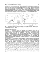
public), Fig. 7, or calculated based on the relation used in steam turbine stage calculations:
2
2
T
T
To
(5)
where - related turbine speed indicator,
To
- maximal turbine efficiency and the
corresponding speed indicator.
0,72
0,74
0,76
0,78
0,8
0,82
0,84
1,2 1,4 1,6 1,8 2 2,2 2,4 2,6 2,8 3 3,2 3,4 3,6
Turbine pressure ratio
Turbine efficiency
_______ turbine of S – wheel type ________ turbine of R – wheel type
Fig. 7. Turbocharger turbine efficiency as a function of scavenge air pressure, acc. to (Schrott,
1995)
Advances in Gas Turbine Technology
54
The turbine speed indicator is defined as:
2
2
sT
uu
cH
(6)
where u- circumferential velocity on the turbine stage pitch diameter, H
T
- enthalpy drop in
the turbine.
The calculations make use of static characteristics of the turbocharger compressor, with the
marked line of cooperation with the Diesel engine, Fig.8.
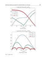
Figure 9 shows the turbocharger efficiency curves calculated from the relation:
TC T C m
(7)
where
T
- the turbocharger turbine efficiency is calculated from relation (5), while the
compressor efficiency
C
is calculated from the line of Diesel engine/compressor
cooperation,
m
– mechanical efficiency of the turbocharger, Fig. 8. In the same figure a
comparison is made between the calculated turbocharger turbine efficiency with the
producer’s data as a function of the Diesel engine scavenge pressure. The differences
between these curves do not exceed 1,5%.
For the presently available turbocharger efficiency ranges, the amount of the exhaust gas
needed for driving the turbocharger turbine is smaller than the entire mass flow rate of the
exhaust gas leaving the Diesel engine. Fig. 10 shows sample curves of exhaust gas
Fig. 8. Diesel engine cooperation line against turbocharger compressor characteristics
Possible Efficiency Increasing of Ship Propulsion and Marine Power Plant with
the System Combined of Marine Diesel Engine, Gas Turbine and Steam Turbine
55
0,550
0,600
0,650
0,700
0,750
0,800
0,850
1,25 1,5 1,75 2 2,25 2,5 2,75 3
p
D
[bar]
TD
_
_
______ turbocharger efficiency, acc. to producer _____ gas turbine efficiency, acc. to producer ●,
▲calculated efficiency
Fig. 9. Efficiency characteristics of the turbocharger and the turbocharger gas turbine as a
function of scavenge air pressure
250
300
350
400
450
500
60 70 80 90 100 110
N
D
/N
Do
[%]
Temperature [oC]
0,75
0,8
0,85
0,9
Relative mass flow
______ temperature in the Diesel engine exhaust gas collector-calculated curves ______ exhaust gas
temperature at turbocharger outlet – producer’s data ______ Diesel engine exhaust gas mass flow rate
related to the scavenge air mass flow rate
Fig. 10. Sample temperature characteristics of the turbocharger during gas expansion in the
turbine to the atmospheric pressure and the related exhaust gas mass flow rates as functions
of Diesel engine load
Advances in Gas Turbine Technology
56
temperature changes in the engine manifold (calculated using the relation (4)) and the
exhaust gas temperature at the turbocharger outlet (according to the data delivered by the
producer) as functions of engine load, when the standard internal combustion engine
exhaust gas is expanded to the barometric pressure. The figure also shows the Diesel engine
exhaust gas flow rate related to the scavenge air flow rate, as a function of the engine load.
This high efficiency of the turbocharger provides opportunities for installing a power gas
turbine connected in parallel with the turbocharger (variant A).
The turbocharger power balance indicates that in the power gas turbine we can utilise
between 10 and 24% of the flow rate of the exhaust gas leaving the exhaust manifold of the
piston engine. The power gas turbine can be switched on when the main engine power
output exceeds 60%. For lower power outputs the entire exhaust gas flow leaving the Diesel
engine is to be used for driving the turbocharger.
In variant B of the combined system with the power turbine, the turbocharger is connected
in series with the power gas turbine. Here, the entire amount of the exhaust gas flows
through the turbocharger turbine. Due to the excess of the power needed for driving the
turbocharger, the final expansion pressure at turbocharger turbine output can be higher
than the exhaust gas pressure at waste heat boiler inlet. In this case the expansion ratio in
the turbocharger turbine is given by the relation:
1
1
_
1
1
1
T
aa a
C
TC D g exh D
g
g
a
a
mc t
mct
(8)
where:
C
- compression ratio of the turbocharger compressor.
The exhaust gas temperature at turbocharger outlet is calculated from the formula:
o
__
1
1
273,15 1 1 273,15 [ C]
exh TC exh D T
T
g
g
tt
(9)
Figure 11 shows sample curves of temperature, compression and expansion rate changes in
the turbocharger for variant B: series power turbine supply.
This case provides opportunities for utilising the enthalpy drop of the expanding exhaust
gas in the power turbine. The operation of the power turbine is possible when the Diesel
engine power exceeds 60%.
3.1 Power turbine in parallel supply system (variant A)
The power turbine (Fig.5) is supplied with the exhaust gas from the exhaust manifold. The
exhaust gas mass flow rate m
PT
and temperature t
exh_D
are identical as those at turbocharger
outlet: the mass flow rate of the exhaust gas flowing through the power turbine results from
the difference between the mass flow rate of the Diesel engine exhaust gas and of that
expanding in the turbocharger:
(1 )
TD a
f
D
mm mm
(10)
Possible Efficiency Increasing of Ship Propulsion and Marine Power Plant with
the System Combined of Marine Diesel Engine, Gas Turbine and Steam Turbine
57
290
310
330
350
370
390
410
430
450
470
490
60 70 80 90 100 110
N
D
/N
Do
[%]
Temperature [ oC ]
1,2
1,6
2
2,4
2,8
Expansion ratio
_____expansion ratio in the turbocharger turbine (standard arrangement - without power turbine) _ _
_ expansion ratio in the turbocharger turbine with power turbine ______exhaust gas temperature in the
Diesel engine exhaust gas collector ____exhaust gas temperature at turbocharger outlet without power
turbine _ _ _ exhaust gas temperature at turbocharger outlet with power turbine
Fig. 11. Changes of temperature and expansion ratio of the turbocharger in the combined
system with series power turbine supply (variant B)
The mass flow rate of the exhaust gas needed by the turbocharger is calculated from the
turbocharger power balance using the following formula:
1
_
1
1
1
1
g
exh D
TC
T
TC
aap
C
g
g
a
a
c
T
m
m
mTc
(10.1)
The exhaust gas expanding in the power turbine has the inlet and outlet pressures identical
to those of the exhaust gas flowing through the turbocharger. The power of the power
turbine is given by the relation:
PT m PT PT PT
NmH
(11)
where
m
- mechanical efficiency of the power turbine, H
PT
– iso-entropic enthalpy drop in
the power turbine.
The power turbine efficiency
PT
is assumed in the same way as for the turbocharger
turbine, Fig. 9, or using the relation (5). In the shipbuilding, the gas turbines used in
combined Diesel engine systems with power turbines are those adopted from turbochargers.
Advances in Gas Turbine Technology
58
The power turbine system calculations show that the exhaust gas temperature at the power
turbine outlet is slightly higher than that at the turbocharger outlet, Fig.12. The increase of
the main engine load results in the increase of both the exhaust gas temperature in the
exhaust gas collector and the mass flow rate of the exhaust gas flowing through the power
turbine. The increase in power of the combined system with additional power turbine
ranges from about 2% for Diesel engine loads of an order of 70% up to over 8% for maximal
loads, Fig.12.
290
300
310
320
330
340
60 70 80 90 100 110
N
D
/N
Do
[%]
Ttemperature [oC]
0
5
10
15
20
Relative gas flow, Relative power [%]
_____ temperature at turbocharger outlet _____ temperature at power turbineoutlet _____ related
exhaust gas mass flow rate in power turbine _____ related power turbine power
Fig. 12. Parameters of parallel supplied power turbine as functions of the main engine load –
variant A (calculations for tropical conditions)
When the Diesel engine power is lower than 60-70% of the nominal value the entire
exhaust gas flow from the exhaust manifold is directed to the turbocharger drive. In this
case the control system closes the valve controlling the exhaust gas flow to the power
turbine, Fig. 5.
3.2 Power turbine in series supply system (variant B)
In this variant the power turbine is supplied with the full amount of the exhaust gas leaving
the Diesel engine exhaust manifold. The power turbine is installed after the turbocharger.
The exhaust gas pressure at the power turbine inlet depends on the pressure of the exhaust
gas leaving the turbocharger turbine, Fig.11.
In this case the power of the power turbine is calculated as:
_
1
1
1
PT PT D g inl PT
PT
g
g
Nmct
(12)
Possible Efficiency Increasing of Ship Propulsion and Marine Power Plant with
the System Combined of Marine Diesel Engine, Gas Turbine and Steam Turbine
59
where t
inl_PT
- exhaust gas temperature at the power turbine inlet,
PT
– expansion ratio in the
power turbine ,
PT
- power turbine efficiency. The power turbine efficiency is assumed in
the same way as in variant A.
In formula (12) the exhaust gas temperature at the power turbine inlet is assumed equal to
that of the exhaust gas leaving the turbocharger, Fig. 13.
The exhaust gas temperature at the power turbine output is calculated from the formula:
__
1
1
273,15 1 1 273,15[ ]
o
exh PT inl PT PT
PT
g
g
tt C
(13)
Figure 13 also shows the expansion ratio, the power of the power turbine, and the exhaust
gas temperatures at the turbocharger and the power turbine outlets for partial engine loads.
The power turbine in this variant increases the power of the combined system by 3% to 9%
with respect to that of a standard engine. The turbine power increases with increasing Diesel
engine load.
300
320
340
360
380
60 70 80 90 100 110
N
D
/N
Do
[ % ]
temperature [ oC ]
0
0,2
0,4
0,6
0,8
1
1,2
1,4
Expansion ratio [-], Relative power x10 [%]
____ temperature at turbocharger outlet ____ temperature at power turbine outlet
____ expansion ratio in power turbine ____ related power of power turbine
Fig. 13. Parameters of series supplied power turbine as functions of the main engine load -
variant B (calculations for tropical conditions)
3.3 Comparing the two power turbine supply variants
The analysis of the two examined variants shows that the power of the combined system
increases depending on the Diesel engine load. For both variants the power turbine can be
Advances in Gas Turbine Technology
60
used after exceeding about 65% of the Diesel engine power. The exhaust gas leaving the
power turbine is directed to the waste heat boiler, where together with steam turbine it can
additionally increase the overall power of the combined system.
In both cases the temperatures of the exhaust gas leaving the power turbine are comparable.
The exhaust gas pressure at power turbine outlet depends on the losses generated when the
gas flows through the waste heat boiler and outlet silencers. Following practical experience,
the exhaust gas back pressure is assumed higher than the barometric pressure by 300
mmWC, i.e. about 3%. Taking into account powers of the power turbines for the above
variants, Fig. 14, it shows that for the same Diesel engine parameters the series supply of the
power turbine results in higher turbine power. For lower loads, the power of the series
supplied power turbine increases, compared to the parallel supply variant.
4. Steam turbine circuit
The combined system makes use of the waste heat from the Diesel engine. In modern Diesel
engines the temperatures of the waste heat are at the advantageous levels for the steam
turbine circuit. This circuit makes use of water that can be utilised in a low-temperature
process. Adding the steam circuit to the combined Diesel engine/power gas turbine system
provides good opportunities for increasing the power of the combined system, and
consequently, also the system efficiency, see formula (2).
In the examined combined system the exhaust gas leaving the turbocharger and the
power turbine (variant A, Fig. 5) or only the power turbine (variant B, Fig. 6) flows to the
waste heat boiler where it is used for producing superheated steam for driving the steam
turbine.
The mass flow rate of the exhaust gas reaching the waste heat boiler is equal to that leaving
the Diesel engine exhaust gas collector. The exhaust gas temperature at waste heat boiler
inlet depends on the adopted solution of power turbine supply. For variant A with parallel
supply it is calculated from the balance of mixing of the gases leaving the turbocharger and
the power turbine:
__
_
273,15 [ ]
o
TC exh TC PT exh PT
inl B
Dg
mi mi
tC
mc
(14)
while for the series power turbine supply (variant B) it is assumed equal to that at the power
turbine outlet, formula (13).
In combined steam turbine systems for small power ranges and low live steam temperatures
the single pressure systems are used, Fig. 15, (Kehlhofer, 1991).
Such system consists of a single-pressure waste heat boiler, a condensing steam turbine, a
water-cooled condenser, and a single stage feed water preheater in the deaerator.
The main disadvantage of the systems of this type is poor utilisation of the heat contained in
the exhaust gas (the waste heat energy). The steam superheater is relatively large, as the
entire mass of the steam produced by the boiler flows through it. However, costs of this
steam system are the lowest, as poor utilisation of the exhaust gas energy results in high
temperature of the exhaust gas leaving the boiler. The deaerator is supplied with the steam
extracted from the steam turbine. The application of the single pressure system does not
secure optimal utilisation of the exhaust gas energy.
Possible Efficiency Increasing of Ship Propulsion and Marine Power Plant with
the System Combined of Marine Diesel Engine, Gas Turbine and Steam Turbine
61
0
1
2
3
4
5
6
7
8
9
60 70 80 90 100 110
N
D
/N
Do
[%]
Relative power [%]
10
15
20
25
30
Difference power [%]
____ parallel power turbine supply (variant A) ____ series power turbine supply (variant B)
Fig. 14. Powers of the power turbine as functions of main engine load
1-Waste Heat Boiler 2-Superheater 3- Evaporator 4-Ekonomizer 5-Boiler drum 6-Steam turbine 7-
Condenser 8-Deaerator 9-Feed water pump 10-Condensate pump
Fig. 15. Flow Diagram of the Single Pressure System
Advances in Gas Turbine Technology
62
Those steam turbine systems frequently make use of an additional low-pressure evaporator,
Fig. 16, which leads not only to more intensive utilisation of the waste heat contained in the
exhaust gas, but also to better thermodynamic use of the low-pressure steam.
In this solution the high pressure superheater is relatively small, compared to the single
pressure boiler. The deaerator is heated with the saturated steam from the low-pressure
evaporator. The power of the main high-pressure feeding pump is also smaller. The excess
steam from the low-pressure evaporator can be used for supplying the low-pressure part of
the steam turbine, thus increasing its power, or, alternatively, for covering all-ship needs.
Figure 16 shows possible use of the temperature waste heat from the scavenge air cooler,
the lubricating oil cooler, and from the jacket water cooler in the low-pressure water pre-
heater.
The additional low-pressure exchanger in the steam circuit, Fig. 16, makes it possible to
increase the temperature of the water in the deaerator. Higher water temperature is required
due to the presence of sulphur in the fuel (water dew-point in the exhaust gas) – it is
favourable for systems fed with a high sulphur content fuel. If the temperature of the
feedwater is low when the system is fed with fuel without sulphur, the heat exchanger 14 in
Fig. 16 is not necessary and the waste heat from the coolers can be used in the deaerator.
For a low feedwater temperature the deaerator works at the pressure below atmospheric
(under the vacuum).
1-Waste Heat Boiler 2-High pressure superheater 3- High pressure evaporator 4- High pressure
economizer 5- High pressure boiler drum 6 -Steam turbine 7-Condenser 8- Deaerator 9-High pressure
feed water pump 10-Condensate pump 11-Low pressure feed pump 12-Low pressure evaporator 13-
Low pressure boiler drum 14-Low pressure pre-heater
Fig. 16. Flow Diagram for a Two – Pressure System
Possible Efficiency Increasing of Ship Propulsion and Marine Power Plant with
the System Combined of Marine Diesel Engine, Gas Turbine and Steam Turbine
63
4.1 Limits for steam circuit parameters
The limits for the values of the steam circuit parameters result from strength and technical
requirements concerning the durability of particular system components, but also from
design and economic restrictions. The difference between the exhaust gas temperature and
the live steam temperature, t, for waste heat boilers used in shipbuilding is assumed as t
= 10-15
o
C, according to (MAN, 1985; Kehlhofer, 1991). The “pitch point” value
recommended by MAN B&W (MAN, 1985) for marine boilers is t = 8-12
o
C. The limiting
dryness factor x of the steam downstream of the steam turbine is assumed as x
limit
=0,86-0,88.
For marine condensers cooled with sea water, MAN recommends the condenser pressure
p
K
=0,065 bar. This pressure depends on the B&W (MAN, 1985) temperature of the cooling
medium in the condenser. Figure 17 shows the dependence of the condenser pressure on
the cooling medium temperature. The temperature of the boiler feed water is of high
importance for the life time of the feed water heater in the boiler. The value of this
temperature is connected with a so-called exhaust gas dew-point temperature. Below this
temperature the water condensates on heater tubes and reacts with the sulphur trioxide SO
3
producing the sulphuric acid, which is the source of low-temperature corrosion. That is why
boiler producers give minimal feed water temperatures below which boiler operation is
highly not recommended. The dew-point temperature is connected with the content of
sulphur in the fuel and depends on the excess air coefficient in the piston engine. Figure 18
shows the dew-point temperature as the function of: sulphur content in the fuel, SO
2
conversion to SO
3
, and the excess air coefficient in the engine. In inland power installations
burning fuels with sulphur content higher than 2%, the recommended level of feed water
temperature is t
FW
> 140-145
o
C (Kehlhofer, 1991).
0
5
10
15
20
25
30
35
40
-20-100 1020304050
Temperature of the cooling medium [
o
C]
Condenser pressure [kPa]
____ Fresh Water Cooling ____ Wet Cooling Tower ____ Direct Air Condensation
Fig. 17. Condenser pressure as a function of temperature of the cooling medium
Advances in Gas Turbine Technology
64
In marine propulsion (MAN, 1985) recommends that the feed water temperature should not
be lower than 120
o
C when the sulphur content is higher than 2%. This is justified by the fact
that the outer surface of the heater tubes on the exhaust gas side has the temperature higher
by 8-15
o
C than the feed water temperature, and that the materials used in those heaters
reveal enhanced resistance to acid corrosion.
The exhaust gas temperature at the boiler outlet is assumed higher by 15-20
o
C than the feed
water temperature, i.e. t
exh
> t
FW
+ (15 – 20
o
C).
Each ship burning heavy fuel in its power plant uses the mass flow rate m
SS
of the saturated
steam taken from the waste heat boiler for fuel pre-heating and all-ship purposes. According
to the recommendations (MAN, 1985) the pressure of the steam used for these purposes
should range between p
SS
= 7-9 bar. This pressure is also assumed equal to the pressure in
the boiler low-pressure circuit. The back temperature of the above steam flow in the heat
box is within 50 – 60
o
C.
60
70
80
90
100
110
120
130
140
150
0,01 0,1 1 10
Sulphur content in the fuel [%]
Acid dew-point [oC]
______ ______ ______ ______ ______
Fig. 18. Acid dew-point as a function of the sulphur content in the fuel and the excess air
coefficient
4.2 Optimising the steam circuit
Optimisation of the steam system is to be done in such a way so as to reach the maximal
possible utilisation of the heat contained in the exhaust gas. In this sense the optimisation is
reduced to selecting the steam circuit parameters for which the steam turbine reaches the
highest power. The area of search for optimal steam circuit parameters is to be narrowed to
Possible Efficiency Increasing of Ship Propulsion and Marine Power Plant with
the System Combined of Marine Diesel Engine, Gas Turbine and Steam Turbine
65
the sub-area where the earlier discussed limits imposed on the steam system are met. The
use of the steam system with the waste heat boiler increases the power of the propulsion
system within the entire range of the main engine load.
Adding a steam turbine to the Diesel engine system increases the power of the propulsion
system by N
ST
/N
D
= 6,5 – 7,5% for main engine loads ranging from 90 to 100%. The power
of the steam turbine for both examined variants of power turbine supply are comparable,
and slightly higher power, by about 2-4%, is obtained by the steam turbine in the variant
with series power turbine supply.
The analysis of the system with an additional exchanger utilising the low-temperature waste
heat from the Diesel engine to heat the condensate from the condenser before the deaerator,
Fig.16, shows that the steam turbine power increases by 7- 11% with respect to that of the
steam turbine without this exchanger.
The requirements concerning the waste heat boiler refer to low loss of the exhaust gas flow
(which reduces the final expansion pressure in the power turbine) and small temperature
concentrations (pitch points) in the boiler evaporators. There is a remarkable impact of the
sulphur content in the fuel on the permissible exhaust gas temperature and the lower feed
water temperature limit. In the steam turbine circuit, a minimal number of exchangers
should be used (optimally: none). The optimal parameters of this circuit also depend on the
piston engine load.
5. Conclusions
It is possible to implement a combined system consisting of a Diesel engine as the leading
engine, a power gas turbine, and a steam turbine circuit utilising the heat contained in the
Diesel engine exhaust gas. Such systems can reveal thermodynamic efficiencies comparable
with combined gas turbine circuits connected with steam turbines.
5.1 Power range of combined systems
Depending on the adopted variant and the main engine load, the use of the combined
system makes it possible to increase the power of the power plant by 7 to 15 % with respect
to the conventional power plant burning the same rate of fuel. Additional power is obtained
by the system due to the recovery of the energy contained in the exhaust gas leaving the
piston internal combustion engine. Thus the combined system decreases the specific fuel
consumption by 6,4 – 12,8 % compared to the conventional power plant.
In the examined systems the power of the steam turbine is higher than that of the power
turbine by 6-29 %, depending on the system variant and the main engine load.
5.2 Efficiency of combined systems
The use of the combined system for ship propulsion increases the efficiency of the
propulsion system, and decreases the specific fuel consumption. Additionally, it increases
the propulsion power without additional fuel consumption.
Like the power, the efficiency of the combined system increases with respect to the
conventional power plant by 7 to 15% reaching the level of 53 - 56% for maximal power
ranges. These efficiency levels are comparable with the combined systems based on the
steam/gas turbines, Fig. 1. For partial loads the efficiency curves of the combined system
Advances in Gas Turbine Technology
66
with the Diesel engine are more flat than those for the combined turbine systems (smaller
efficiency decrease following the load decrease) .
In the combined system the maximal efficiency is reached using particular system
components:
-
the piston internal combustion engine with the maximal efficiency;
-
Turbocharger. The turbocharger with the maximal efficiency should be used as it
provides opportunities for decreasing the exhaust gas enthalpy drop in the turbine in
case of the series supply variant, or exhaust gas mass flow rate in case of the parallel
supply variant, which in both cases results in higher power of the power turbine;
-
Power turbine. High efficiency is required to increase its power;
-
Steam turbine circuit. The requirement is to obtain the maximal power of the steam
turbine from the heat delivered in the exhaust gas flowing through the boiler.
5.3 Ecology
Along with the thermodynamic profits, having the form of efficiency increase, and the
economic gains, reducing the fuel consumption for the same power output of the propulsion
system, the use of the combined system brings also ecological profits. A typical new-
generation low-speed piston engine fed with heavy fuel oil with the sulphur content of 3%
emits 17g/kWh NOx, 12g/kWh SOx and 600g/kWhCO
2
to the atmosphere. The use of the
combined system reduces the emission of the noxious substances by, respectively, g/kWh
NOx, g/kWh SOx and g/kWhCO
2
. The emission decreases by % with respect to the
standard engine, solely because of the increased system efficiency, without any additional
installations.
Depending on the adopted solution, the combined power plant provides opportunities for
reaching the assumed power of the propulsion system at a lower load of the main Diesel
engine, at the same time also reducing the fuel consumption.
The article presents the thermodynamic analysis of the combined system consisting of the
Diesel engine, the power gas turbine, and the steam turbine, without additional technical
and economic analysis which will fully justify the application of this type of propulsion
systems in power conversion systems.
6. Nomenclature
b
e
- specific fuel oil consumption
c
g
, c
a
- specific heat of exhaust gas and air, respectively
i - specific enthalpy
m - mass flow rate
N - power
p - pressure
T,t - temperature
Wu - calorific value of fuel oil
- efficiency
g
,
a
- isentropic exponent of exhaust gas and air, respectively
Possible Efficiency Increasing of Ship Propulsion and Marine Power Plant with
the System Combined of Marine Diesel Engine, Gas Turbine and Steam Turbine
67
Indices:
a - air
bar - barometric conditions
B - Boiler
C - Compressor
combi - combined system
D - Diesel engine
d - supercharging
exh - exhaust passage
f - fuel
FW - feet water
g - exhaust gas
inlet - inlet passage
k - parameters in a condenser
o - live steam, calculation point
PT - Power turbine
ST - Steam turbine
ss - ship living purposes
T - Turbine
TC - Turbocharger
- compression ratio in a compressor, expansion ratio in a turbine
7. References
Dzida, M. (2009). On the possible increasing of efficiency of ship power plant with the
system combined of marine diesel engine, gas turbine and steam turbine at the
main engine - steam turbine mode of cooperation. Polish Maritime Research, Vol. 16,
No.1(59), (2009), pp. 47-52, ISSN 1233-2585
Dzida, M. & Mucharski, J. (2009). On the possible increasing of efficiency of ship power
plant with the system combined of marine diesel engine, gas turbine and steam
turbine in case of main engine cooperation with the gas turbine fed in parallel and
the steam turbine. Polish Maritime Research, Vol 16, No 2(60), pp. 40-44, ISSN 1233-
2585
Dzida, M.; Girtler, J.; Dzida, S. (2009). On the possible increasing of efficiency of ship power
plant with the system combined of marine diesel engine, gas turbine and steam
turbine in case of main engine cooperation with the gas turbine fed in series and
the steam turbine. Polish Maritime Research, Vol 16, No 3(61), pp. 26-31, ISSN 1233-
2585
Kehlhofer, R. (1991). Combined-Cycle Gas & Steam Turbine Power Plants, The Fairmont Press,
INC., ISBN 0-88173-076-9, USA
Advances in Gas Turbine Technology
68
MAN B&M (October 1985). The MC Engine. Exhaust Gas Date. Waste Heat Recovery
System. Total Economy, MAN B&W Publication S.A., Danish
MAN Diesel & Turbo (2010). Stationary Engine. Programme 4
th
edition, Branch of MAN
Diesel & Turbo SE, Germany, Available from www.mandieselturbo.com
Schrott, K. H. (1995). The New Generation of MAN B&W Turbochargers. MAN B&W
Publication S.A., No.236 5581E
Part 2
Gas Turbine Systems
4
Exergy Analysis of a Novel SOFC Hybrid
System with Zero-CO
2
Emission
Liqiang Duan, Xiaoyuan Zhang and Yongping Yang
School of Energy, Power and Mechanical Engineering,
Beijing Key Lab of Energy Safety and Clean Utilization,
Key Laboratory of Condition Monitoring and Control for Power
Plant Equipment of Ministry of Education,
North China Electric Power University, Beijing,
People Republic of China
1. Introduction
Now, climate change due to the emission of greenhouse gases, especially the emission of
CO
2
, is becoming more and more serious. Though many countries have taken all kinds of
measures to control and reduce the emission of CO
2
, in the short term, CO
2
emission still
maintains a rapid growth trend. Power industry is the biggest CO
2
emission sector. So, there
exists the greatest CO
2
emission reduction potential in the power industry. Now, many
kinds of fossil fuel power generation systems with CO
2
recovery are usually based on the
chemical absorption method or the oxygen combustion method. The former demands a
chemical absorption and separation unit to recover CO
2
from the flue gas of power systems.
The latter demands a special oxygen combustion technology, equipment and a larger ASU
(air separation unit). And these technologies all consume great energy and result in the
huger equipment investment and higher operating cost. Now, people are eager to develop
the high-efficiency power generation technology with the less energy consumption for CO
2
capture. Fuel cell can satisfy the above requirements, with the higher energy conversion
efficiency and less energy consumption of CO
2
capture, so it has attracted considerable
interest in recent years.
Solid Oxide Fuel Cell (SOFC) is an attractive power-generation technology that can convert
the chemical energy of fuel directly into electricity while causing little pollution (Kartha &
Grimes, 1994). Because the anode fuel gas is naturally separated from the cathode air by the
solid electrolyte, the CO
2
gas with the higher concentration can be obtained in the anode
exhaust gas. In addition, SOFC can employ all kinds of fuels, including various hydrocarbon
fuels. Compared with the traditional power generation systems, the SOFC hybrid system
power plant has the higher system efficiency (net AC/LHV). Even after CO
2
is captured, the
efficiency of SOFC hybrid system still can be greater than or equal to that of the traditional
power systems without CO
2
capture. In order to further improve the CO
2
concentration of
anode exhaust gas, SOFC can employ the O
2
/CO
2
combustion mode in the afterburner.
Because the required mass flow of pure O
2
is less, the energy consumption is lower. After
capturing the CO
2
, the SOFC hybrid system does not result in a bigger efficiency reduce. So
the SOFC hybrid power system with zero CO
2
emission become a new way which can
Advances in Gas Turbine Technology
72
simultaneously solve the problem of efficient energy utilization and lower pollution
emission.
In the last decades, many researchers were involved in study of SOFC stack and the hybrid
power system with CO
2
capture. Y.Inui proposed and investigated two types of carbon
dioxide recovering SOFC/GT combined power generation systems in which a gas turbine
with carbon dioxide recycle or water vapor injection is adopted at the bottoming cycle
system (Y.Inui et al, 2005). The overall efficiency of the system with carbon dioxide recycle
reaches 63.87% (HHV) or 70.88% (LHV), and that of the system with water vapor injection
reaches 65% (HHV) or 72.13% (LHV). A. Franzoni considered two different technologies for
the same base system to obtain a low CO
2
emission plant (Franzoni et al, 2008). The first
technology employed a fuel decarbonization and CO
2
separation process placed before the
system feed, while the second integrated the CO
2
separation and the energy cycle. The result
showed that the thermodynamic and economic impact of the adoption of zero emission
cycle layouts based on hybrid systems was relevant. Philippe Mathieu presented the
integration of a solid oxide fuel cell operating at a high temperature (900℃–1000℃, 55–60%
efficiency) in a near-zero emission CO
2
/O
2
cycle (Philippe Mathieu, 2004). Takeshi
Kuramochi compared and evaluated the techno-economic performance of CO
2
capture from
industrial SOFC-combined heat and power plant (CHP) (Takeshi et al, 2009). CO
2
is
captured by using an oxyfuel afterburner and conventional air separation technology. The
results were compared to both SOFC-CHP plants without CO
2
capture and conventional gas
engines CHP without CO
2
capture. B.Fredriksson Moller examined the SOFC/GT
configuration with and without a tail-end CO
2
separation plant, and based on a genetic
algorithm, selected the key parameters of the hybirid system (Fredriksson et al, 2004). The
result of the optimization procedure shows that the SOFC/GT system with part capture of
the CO
2
exhibits an electrical efficiency above 60%. Some researchers also studied the
performance parameters of the different SOFC hybrid power systems from the
thermoeconomic or exergy efficiency point (Bozzolo et al, 2003; Asle & Matteo 2001; Takuto
et al, 2007). For example, Ali Volkan Akkaya proposed a new criterion-exergetic
performance coefficient (EPC), then applied it in the SOFC stack and SOFC/GT CHP system
(Ali et al, 2007, 2009). F. Calisa discussed the simulation and exergy analysis of a hybrid
SOFC-GT power system. The result showed that the SOFC stack was the most important
sources of exergy destruction (Calisea et al, 2006).
In this paper, a zero-CO
2
emission SOFC hybrid power system is proposed. Using exergy
analysis method, the exergy loss distributions of every unit of zero-CO
2
emission SOFC
hybrid system are revealed. The effects of different operating parameters on exergy loss of
every unit, as well as the overall system performance, are also investigated. The results
obtained in this paper will provide useful reference for further study on high-efficient zero
emission CO
2
power system.
2. System modelling
The models developed in the paper are all based on the following general assumptions:
1. All components work in adiabatic conditions, pressure drops and refrigerant disclosure
are all neglected, and the systems operate at steady-state conditions.
2. The cathode gas consists of 79% nitrogen and 21% oxygen, and all gases are assumed as
ideal gases.
Exergy Analysis of a Novel SOFC Hybrid System with Zero-CO
2
Emission
73
3. The mass flow of the input fuel, gas and all the reaction products are stable, the changes
of the fluid kinetic energy and potential energy are neglected.
4. The unreacted gases are assumed to be fully oxidized in the after-burner of the SOFC
stack, and the after-burner is assumed to be insulation, all the heat exchangers are
adiabatic.
5. The temperature of the anode and cathode outlet gases are equal to the cell stack
operating temperature, the current and voltage of every cell unit are the same.
2.1 The SOFC stack model and result analysis
2.1.1 SOFC model
The natural gas feed tubular SOFC system process is implemented by using Aspen Plus
software. The Aspen Plus contains rigorous thermodynamic and physical property database
and provides comprehensive built-in process models, thus offering a convenient and time
saving means for chemical process studies, including system modeling, integration and
optimization. The simulated SOFC flowsheet is shown in Figure 1. It includes all the
components and functions contained in the SOFC stack, such as ejector, pre-reformer, fuel
cell (anode and cathode) and afterburner.
Firstly, the preheated fuel (stream 1) mixes with the recycling anode exhausted gas (stream
6), and then the mixed fuel gas (stream 2) is sent to the pre-reformer where the steam reform
reaction takes place. After that, the stream (4) enters the anode of SOFC in which the
electrochemical reaction of fuel and oxygen from the anode occurs. The reaction product
and unreacted flue mixture (stream 5) is separated into two parts. One part (stream 6) is
recycled. Another part enters the afterburner and mixes with the nitrogen-rich air (stream
13) from the anode. After the combustion reaction, the exhausted gas from the afterburner
(stream 14) is introduced into the regenerator to preheat the air (stream 9) for the anode.
Fig. 1. Aspen Plus SOFC Stack Model Flowsheet
The cell voltage calculation is the core of any fuel cell modeling. The semi-empirical equations
from literature (Stefano, 2001) were used to compose the Aspen Plus calculation module to
simulate these effects on voltage. Several Design-spec Fortran blocks are used to set the fuel
cell system’s energy and heat balance. The semi-empirical equations are as follows: