Beginning XNA 2.0 Game Programming From Novice to Professional phần 7 pptx
Bạn đang xem bản rút gọn của tài liệu. Xem và tải ngay bản đầy đủ của tài liệu tại đây (824.24 KB, 45 trang )
9241CH08.qxd 3/18/08 11:56 AM Page 244
Lights, Camera,
Transformations!
In this chapter you’re going to create a basic framework to manage cameras, lights, and
object transformations. A 3-D scene might have many cameras, lights, and objects scat-
tered around it. Because you might have a few different types of cameras and lights in
your scene, creating base classes and managers for them is very helpful. For the objects
in the scene, it’s useful to create a class to store its transformation: translation, rotation,
and scale. The basic concepts related to transformations, cameras, and lights were pre-
sented in Chapter 7; here you’re going to create some classes to represent and manage
these objects. You’ll use the classes created in this chapter in Chapters 10, 11, and 12.
Cameras
Depending on the genre of the game that you’re going to create, you might want to use a
different type of camera, such as a fixed-position camera, a first-person camera, a third-
person camera, a Real Time Strategy (RTS) camera, and so on.With so many different
types of cameras, it is helpful to create a basic camera that can be extended to create
more specific types of cameras.
BaseCamera Class
In this section you’re going to create a generic base class for the cameras, named
BaseCamera. This class will handle the camera view and projection matrices and its visual-
ization volume, a
frustum (truncated pyramid). You can use the camera’s frustum to
identify which objects are not inside the camera’s visualization volume, keeping these
objects out of the rendering process. The camera’s frustum is generated based on the
camera’s view and projection matrices.
245
CHAPTER 9
9241CH09.qxd 3/21/08 10:50 AM Page 245
Camera Perspective Projection
The BaseCamera class only supports perspective projection. You’ll create the
SetPerspectiveFov method to set the camera’s perspective projection, and the Projection
property to retrieve it. You can use the following code to create and update the camera
perspective projection matrix:
// Perspective projection parameters
float fovy;
float aspectRatio;
float nearPlane;
float farPlane;
// Matrices and flags
protected bool needUpdateProjection;
protected bool needUpdateFrustum;
protected Matrix projectionMatrix;
// Get the camera projection matrix
public Matrix Projection
{
get
{
if (needUpdateProjection) UpdateProjection();
return projectionMatrix;
}
}
// Set the camera perspective projection
public void SetPerspectiveFov(float fovy, float aspectRatio, float nearPlane,
float farPlane)
{
this.fovy = fovy;
this.aspectRatio = aspectRatio;
this.nearPlane = nearPlane;
this.farPlane = farPlane;
needUpdateProjection = true;
}
// Update the camera perspective projection matrix
protected virtual void UpdateProjection()
{
// Create a perspective field of view matrix
CHAPTER 9 ■ LIGHTS, CAMERA, TRANSFORMATIONS!246
9241CH09.qxd 3/21/08 10:50 AM Page 246
projectionMatrix = Matrix.CreatePerspectiveFieldOfView(
MathHelper.ToRadians(fovy), aspectRatio, nearPlane, farPlane);
needUpdateProjection = false;
needUpdateFrustum = true;
}
The method SetPerspectiveFov stores the new perspective projection parameters but
does not generate the new projection matrix. Instead, it sets the
needUpdateProjection
variable as true, indicating that the projection matrix needs to be updated before it can
be used. When the perspective projection is retrieved through the
Projection property, it
will update the projection matrix if needed. Finally, inside the
UpdateProjection method
you generate the new perspective projection matrix using the
CreatePerspectiveField-
OfView method of XNA’s Matrix class.
Notice that the camera’s frustum needs to be updated whenever the projection
matrix is updated.
Camera View (Position and Orientation)
The view matrix stores the camera’s position and orientation in the world. You’ll create
the
SetLookAt method to set the camera view matrix, and the View property to retrieve it.
You can use the following code to modify and update the camera’s view matrix:
// Position and target
Vector3 position;
Vector3 target;
// Orientation vectors
Vector3 headingVec;
Vector3 strafeVec;
Vector3 upVec;
// Matrices and flags
protected bool needUpdateView;
protected bool needUpdateFrustum;
protected Matrix viewMatrix;
// Get the camera view matrix
public Matrix View
{
get
{
if (needUpdateView) UpdateView();
CHAPTER 9 ■ LIGHTS, CAMERA, TRANSFORMATIONS! 247
9241CH09.qxd 3/21/08 10:50 AM Page 247
return viewMatrix;
}
}
// Set the camera view
public void SetLookAt(Vector3 cameraPos, Vector3 cameraTarget, Vector3 cameraUp)
{
this.position = cameraPos;
this.target = cameraTarget;
this.upVec = cameraUp;
// Calculate the camera axes (heading, upVector, and strafeVector)
headingVec = cameraTarget - cameraPos;
headingVec.Normalize();
upVec = cameraUp;
strafeVec = Vector3.Cross(headingVec, upVec);
needUpdateView = true;
}
// Update the camera view
protected virtual void UpdateView()
{
viewMatrix = Matrix.CreateLookAt(position, target, upVec);
needUpdateView = false;
needUpdateFrustum = true;
}
The SetLookAt method stores the new view parameters of the camera, but like the
SetPerspectiveFov method, it lets the view matrix be further generated when the view
matrix is retrieved through the
View property. This method also calculates the three vec-
tors that compose the camera’s coordinate system and that are used to orient the camera.
We’ll explain how to calculate these vectors in more detail in the next section.
Last, inside the
UpdateView method you generate the new view matrix using the
CreateLookAt method of XNA’s Matrix class. Notice that the camera’s frustum needs to
be updated whenever the view matrix is updated.
Camera Coordinate System
E
v
ery time you change the camera’s configuration through the
SetLookAt method, y
ou
need to calculate the thr
ee camer
a coordinate system vectors: heading (Z axis), strafe
(X
axis), and up (Y axis). Figure 9-1 illustrates the camera’s coordinate systems placed in
the world coor
dinates system. Notice that because these vectors compose the camera’s
CHAPTER 9 ■ LIGHTS, CAMERA, TRANSFORMATIONS!248
9241CH09.qxd 3/21/08 10:50 AM Page 248
coordinate system, they must be unitary and perpendicular vectors. You can use unitary
vectors to represent directions, because the size of the vector doesn’t matter in this case.
For more information about coordinate systems, refer to Chapter 7.
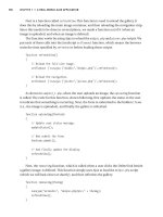
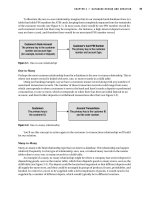
Figure 9-1. Camera’s coordinate system placed in the world coordinates system. The
camera’s X,Y, and Z axes are represented respectively by the strafe, up, and heading
vectors of the BaseCamera class.
The heading vector is the direction from the camera’s position to its target position,
and you can calculate it by subtracting the camera’s position from its target position. The
up vector defines the camera’s up direction and is used to orient the camera. For exam-
ple, you can use the vector
(0, 1, 0) to orient the camera up as the world’s Y axis. You can
calculate the last vector (the strafe vector) by finding a vector that is perpendicular to the
heading and up vectors. The vector cross product is an operation that calculates a vector
that’s perpendicular to two other vectors at the same time. You’ll use the cross product
between the heading and up vectors to calculate the camera’s strafe vector. To calculate a
cr
oss pr
oduct you can use the
Cross method of XNA
’
s
Vector3 class
. N
otice that the vec-
tors used in the cr
oss product operation must be unitary vectors, and the order in which
they ar
e passed to the
Cross method changes the dir
ection of the r
esulting v
ector.
Another impor
tant thing to notice is that in this case
, the up v
ector is user-defined
and not necessar
ily perpendicular to the heading v
ector
, although it is perpendicular to
the str
afe v
ector
. If you do want to make sure the up vector is perpendicular to the head-
ing v
ector
, after calculating the str
afe vector you must calculate a new up vector by a
cr
oss pr
oduct betw
een the heading and strafe vectors.
These thr
ee v
ectors for
m the camera’s coordinate system, and are used whenever you
need to tr
ansfor
m the camera based on its axes; for example, whenever you need to move
the camer
a to
wards the direction it is heading.
CHAPTER 9 ■ LIGHTS, CAMERA, TRANSFORMATIONS! 249
9241CH09.qxd 3/21/08 10:50 AM Page 249
Camera Frustum
You’ll represent the camera’s frustum using XNA’s BoundingFrustum class. XNA has some
classes to represent bounding volumes, such as
BoundingBox (an axis-aligned box),
BoundingSphere, and BoundingFrustum. Each of these classes has collision test methods,
which you can use to check the intersection between them. So, using the XNA
BoundingFrustum class you already have methods to check the intersection with some
different objects.
You’ll create the
UpdateFrustum method to generate the camera’s frustum, and the
Frustum property to retrieve it. You can generate the camera’s frustum by combining
the camera’s view and projection matrices and using it to construct a new XNA
BoundingFrustum. You can use the following code to build the camera’s frustum:
public BoundingFrustum Frustum
{
get
{
if (needUpdateProjection)
UpdateProjection();
if (needUpdateView)
UpdateView();
if (needUpdateFrustum)
UpdateFrustum();
return frustum;
}
}
protected virtual void UpdateFrustum()
{
frustum = new BoundingFrustum(viewMatrix * projectionMatrix);
needUpdateFrustum = false;
}
F
inally
,
the
BaseCamera class has the abstr
act method
Update that defines ho
w the
camer
a should be updated. Each camer
a that extends the
BaseCamera class must imple
-
ment this method.
The
Update method
’
s signatur
e follows:
public abstract void Update(GameTime time);
CHAPTER 9 ■ LIGHTS, CAMERA, TRANSFORMATIONS!250
9241CH09.qxd 3/21/08 10:50 AM Page 250
Third-Person Camera
In this section you’ll extend the BaseCamera class, created in the previous section, to create
a more specific type of camera: a third-person camera. For this type of camera, you’ll
create a class named
ThirdPersonCamera, which extends the BaseCamera class. The third-
person camera’s goal is to follow an object while it moves, and the distance in which the
camera follows an object must be variable. Otherwise, it would appear that the object is
bound to the camera.
To make the camera follow an object, for example the player-controlled character,
you need to define some parameters, such as chase position (the position the camera
must follow); chase direction (the direction used to follow the chase position); chase
speed; and minimum, desired, and maximum distances between the camera and the
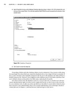
object. Figure 9-2 illustrates some of the parameters that need to be configured.
Figure 9-2. For the third-person camera, the square is the camera’s chase position, and the
dots are the camera’s maximum, desired, and minimum allowed positions.
Setting Chase Parameters
In the ThirdPersonCamera class, you create the SetChaseParameters method to set the cam-
era’s chase parameters that are not frequently updated: the chase distances and speed.
You can configure the chase position and direction parameters, which are more fre-
quently updated, through properties:
// Chase parameters
float desiredChaseDistance;
float minChaseDistance;
float maxChaseDistance;
float chaseSpeed;
CHAPTER 9 ■ LIGHTS, CAMERA, TRANSFORMATIONS! 251
9241CH09.qxd 3/21/08 10:50 AM Page 251
Vector3 chasePosition;
public Vector3 ChasePosition
{
get { return chasePosition; }
set { chasePosition = value; }
}
Vector3 chaseDirection;
public Vector3 ChaseDirection
{
get { return chaseDirection; }
set { chaseDirection = value; }
}
public void SetChaseParameters(float chaseSpeed,
float desiredChaseDistance, float minChaseDistance, float maxChaseDistance){
this.chaseSpeed = chaseSpeed;
this.desiredChaseDistance = desiredChaseDistance;
this.minChaseDistance = minChaseDistance;
this.maxChaseDistance = maxChaseDistance;
}
Updating the Camera’s Position
Every time the camera is updated, its position needs to be recalculated. The desired cam-
era position is equal to the camera’s chase position, minus the chase direction, multiplied
by the chase distance (which is the distance between the camera and the chase position),
as shown in Figure 9-2. The desired camera position would be the camera’s final position
if it were placed at a fixed distance from the chase position. However, to allow the camera
to move smoothly, the distance between the camera and the chase position may vary
between a minimum and maximum range (defined in the attributes
minChaseDistance
and maxChaseDistance). This way, the new camera position is calculated through a linear
interpolation between its current position and its desired position. You can see the “Lin-
ear Interpolation” note for more details.
Vector3 targetPosition = chasePosition;
Vector3 desiredCameraPosition = chasePosition –
chaseDirection * desiredChaseDistance;
float interpolatedSpeed = MathHelper.Clamp(chaseSpeed *
elapsedTimeSeconds, 0.0f, 1.0f);
CHAPTER 9 ■ LIGHTS, CAMERA, TRANSFORMATIONS!252
9241CH09.qxd 3/21/08 10:50 AM Page 252
desiredCameraPosition = Vector3.Lerp(position, desiredCameraPosition,
interpolatedSpeed);
The weight used to interpolate the camera’s position is calculated based on the time
elapsed since the last update and the camera speed. However, because the interpolation
weight must be between
0 and 1, you need to clamp its value. XNA’s Vector3 class has a
Lerp method that helps you interpolate vectors.
LINEAR INTERPOLATION
A linear interpolation is an interpolation between two values that varies linearly according to a defined
weight, where the weight is usually a float number defined between
0 and 1. For example, a linear
interpolation between the numbers
10 and 20 using the weight value 0.5 results in the value 15, while
a linear interpolation using the weights
0 and 1 results in the values 10 and 20. Also, a linear interpola-
tion between two 3-D vectors interpolates the value of each component of the vectors (X, Y, Z) linearly.
Create the UpdateFollowPosition method to update the camera’s position. Following
is the code for the
UpdateFollowPosition method:
private void UpdateFollowPosition(float elapsedTimeSeconds,
bool interpolate)
{
Vector3 targetPosition = chasePosition;
Vector3 desiredCameraPosition = chasePosition- chaseDirection *
desiredChaseDistance;
if (interpolate)
{
float interpolatedSpeed = MathHelper.Clamp(
chaseSpeed * elapsedTimeSeconds, 0.0f, 1.0f);
desiredCameraPosition = Vector3.Lerp(position,
desiredCameraPosition, interpolatedSpeed);
// Clamp the min and max follow distances
Vector3 targetVector = desiredCameraPosition - targetPosition;
float targetLength = targetVector.Length();
targetVector /= targetLength;
if (targetLength < minChaseDistance)
{
desiredCameraPosition = targetPosition +
targetVector * minChaseDistance;
CHAPTER 9 ■ LIGHTS, CAMERA, TRANSFORMATIONS! 253
9241CH09.qxd 3/21/08 10:50 AM Page 253
}
else if (targetLength > maxChaseDistance)
{
desiredCameraPosition = targetPosition +
targetVector * maxChaseDistance;
}
}
// Needed to recalculate heading, strafe, and up vectors
SetLookAt(desiredCameraPosition, targetPosition, upVec);
}
The UpdateFollowPosition method has the interpolate parameter, which defines
whether the camera will be placed at its desired position (if the
interpolate value is
false), or will be smoothly interpolated to the desired position. When the camera chases
an object for the first time, you must set the
interpolate value as false, forcing the cam-
era to start at its desired position.
When the final camera position is calculated by interpolating its current position
with its desired position, you need to check if the distance from the camera to the chase
position is between the minimum and maximum chase distances defined, as shown in
Figure 9-2. If the distance is smaller than the minimum, you set it to the minimum
allowed distance. Otherwise, if the camera distance is greater than the maximum dis-
tance, you set it to the maximum allowed distance. These tests are important and they
ensure that the camera can chase objects that have a greater speed than the camera.
Rotating the Camera Around the Target
The last feature you’ll add to the camera is the ability to rotate it around its target. For
that feature, you’ll add two new attributes and a property to the
ThirdPersonCamera class:
// Maximum allowed rotation
public static float MAX_ROTATE = 30.0f;
// Current rotation angle over the camera axes (heading, up, and strafe)
Vector3 eyeRotate;
// Rotation velocity over the camera axes
Vector3 eyeRotateVelocity;
public Vector3 EyeRotateVelocity
{
get { return eyeRotateVelocity; }
set { eyeRotateVelocity = value; }
}
CHAPTER 9 ■ LIGHTS, CAMERA, TRANSFORMATIONS!254
9241CH09.qxd 3/21/08 10:50 AM Page 254
The allowed camera rotation range is defined between the -MAX_ROTATE and
MAX_ROTATE values, and if the camera rotation is outside this range it is clamped. The
eyeRotate vector stores the current camera rotation, where the X, Y, and Z components of
this vector represent the angle of the rotation around the camera’s strafe, up, and heading
axes. Finally, the
eyeRotateVelocity vector stores the velocity in which the camera rota-
tion angle is updated.
To calculate the camera view matrix taking into account the camera rotation, you’ll
need to overwrite the
UpdateView method of the BaseCamera class. Remember that the
UpdateView method is called when the camera view matrix is retrieved through the View
property, and needs to be updated. Following is the code for the UpdateView method of
the
ThirdPersonCamera class:
protected override void UpdateView()
{
Vector3 newPosition = Position - Target;
// Calculate the new camera position, rotating it around its axes
newPosition = Vector3.Transform(newPosition,
Matrix.CreateFromAxisAngle(UpVector,
MathHelper.ToRadians(eyeRotate.Y)) *
Matrix.CreateFromAxisAngle(StrafeVector,
MathHelper.ToRadians(eyeRotate.X)) *
Matrix.CreateFromAxisAngle(HeadingVector,
MathHelper.ToRadians(eyeRotate.Z))
);
viewMatrix = Matrix.CreateLookAt(newPosition + Target,
Target, UpVector);
needUpdateView = false;
needUpdateFrustum = true;
}
In the overwritten UpdateView method, you need to calculate the camera’s position
considering its rotation. The camera rotation is stored in the
eyeRotation attribute and is
relative to its axes. To rotate the camera around its own axes you’ll need to create a rota-
tion matr
ix that r
otates ar
ound an arbitr
ar
y axis
. You can create this matrix using the
CreateFromAxisAngle method of XNA
’
s
Matrix class
.
Then, y
ou can calculate the final
matr
ix used to r
otate the camer
a b
y combining the matr
ices that r
otate the camera
ar
ound its
Y
, X, and Z axes
in or
der
.
CHAPTER 9 ■ LIGHTS, CAMERA, TRANSFORMATIONS! 255
9241CH09.qxd 3/21/08 10:50 AM Page 255
Updating the Camera
You must implement a final method in the ThirdPersonCamera class: the Update method.
The
Update method is an abstract method of the BaseCamera class, which is called every
time the camera needs to be updated. Inside the
Update method you need to update the
camera’s attributes, as well as call the methods used to update the camera. Note that the
UpdateView and UpdateProjection methods use the camera’s attributes to update the cam-
era’s view and projection matrix. These methods are only called when the view and
projection matrices are retrieved through properties and need to be updated. Following
is the code for the
Update method of the ThirdPersonCamera class:
public override void Update(GameTime time)
{
float elapsedTimeSeconds =
(float)time.ElapsedGameTime.TotalSeconds;
// Update the follow position
UpdateFollowPosition(elapsedTimeSeconds, !isFirstTimeChase);
if (isFirstTimeChase)
{
eyeRotate = Vector3.Zero;
isFirstTimeChase = false;
}
// Calculate the new rotation based on the rotation speed
if (eyeRotateVelocity != Vector3.Zero)
{
eyeRotate += eyeRotateVelocity * elapsedTimeSeconds;
eyeRotate.X = MathHelper.Clamp(eyeRotate.X,
-MAX_ROTATE, MAX_ROTATE);
eyeRotate.Y = MathHelper.Clamp(eyeRotate.Y,
-MAX_ROTATE, MAX_ROTATE);
eyeRotate.Z = MathHelper.Clamp(eyeRotate.Z,
-MAX_ROTATE, MAX_ROTATE);
needUpdateView = true;
}
}
I
n the
Update method, y
ou first update the camer
a
’s position using the
UpdateFollowPosition method.
Then y
ou calculate the camer
a’s current rotation
based on its r
otation v
elocity and the elapsed time since the last
update.
CHAPTER 9 ■ LIGHTS, CAMERA, TRANSFORMATIONS!256
9241CH09.qxd 3/21/08 10:50 AM Page 256
Lights
Lights make a big contribution to the realism of a game. A game scene can have various
light sources scattered around it, which can be, for example, activated or deactivated
dynamically depending on the player’s position. The main drawback of placing many
lights in a scene is that the higher the number of light sources, the higher the processing
needed to render the scene. Some types of light sources used in games are directional
light (for example, sunlight), spotlight (as the name says), and point light (a point that
emits light in all directions).
Base Light
In this section you’ll create a base class for all the lights, named BaseLight. The BaseLight
class doesn’t have any methods, besides its constructor, and because the light sources
don’t share many resources, you only store the light source color inside this class:
// Light diffuse and specular color
Vector3 color;
public Vector3 Color
{
get { return color; }
set { color = value; }
}
The color attribute of the BaseLight class is used as the color of the diffuse and specu-
lar components of the light. Another alternative would be to store the colors of the
diffuse and specular components separately. Note that the
(X, Y, Z) components of the
color vector are used to represent a color in the RGB format. Also, note that the lights
don’t have an ambient component. You’ll later define the color of the light’s ambient
component globally for the entire scene, not for every light source.
Point Light/Ominidirectional Light
In this section you’ll extend the BaseLight class to create a more specific type of light: a
point light (or ominidirectional light). Point lights are easy to handle, and you can use
them to light up your scenes. For this type of light, you’ll create a class named
PointLight,
which extends the
BaseLight class.
Point lights are so simple that you only need to store the light position inside the
PointLight class:
CHAPTER 9 ■ LIGHTS, CAMERA, TRANSFORMATIONS! 257
9241CH09.qxd 3/21/08 10:50 AM Page 257
// Omnidirectional light position
Vector3 position;
public Vector3 Position
{
get { return position; }
set { position = value; }
}
Besides their position, you could also store the range of the point lights, which you
could use to calculate the light’s attenuation. However, to simplify the illumination calcu-
lus, only the light position is stored.
Camera and Light Manager
To ease the camera and light management for the game, you’ll create two different man-
agers: one for cameras and another for lights.
Camera Manager
In this section you’ll create a class to manage the cameras, named CameraManager. The
camera manager allows many cameras to be placed in the scene, managing which cam-
era is active at a determined time. The active camera is the camera from where the scene
is observed. Following is the complete code for the
CameraManager class:
public class CameraManager
{
// Active camera index and reference
int activeCameraIndex;
BaseCamera activeCamera;
// Sorted list containing all cameras
SortedList<string, BaseCamera> cameras;
#region Properties
public int ActiveCameraIndex
{
get { return activeCameraIndex; }
}
public BaseCamera ActiveCamera
{
get { return activeCamera; }
}
CHAPTER 9 ■ LIGHTS, CAMERA, TRANSFORMATIONS!258
9241CH09.qxd 3/21/08 10:50 AM Page 258
public BaseCamera this[int index]
{
get { return cameras.Values[index]; }
}
public BaseCamera this[string id]
{
get { return cameras[id]; }
}
public int Count
{
get { return cameras.Count; }
}
#endregion
public CameraManager()
{
cameras = new SortedList<string, BaseCamera>(4);
activeCameraIndex = -1;
}
public void SetActiveCamera(int cameraIndex)
{
activeCameraIndex = cameraIndex;
activeCamera = cameras[cameras.Keys[cameraIndex]];
}
public void SetActiveCamera(string id)
{
activeCameraIndex = cameras.IndexOfKey(id);
activeCamera = cameras[id];
}
public void Clear()
{
cameras.Clear();
activeCamera = null;
activeCameraIndex = -1;
}
public void Add(string id, BaseCamera camera)
{
cameras.Add(id, camera);
CHAPTER 9 ■ LIGHTS, CAMERA, TRANSFORMATIONS! 259
9241CH09.qxd 3/21/08 10:50 AM Page 259
if (activeCamera == null)
{
activeCamera = camera;
activeCameraIndex = -1;
}
}
public void Remove(string id)
{
cameras.Remove(id);
}
}
In the CameraManager class, the cameras are stored in a SortedList, which has a string
containing the camera name as its key. With that, the cameras can be accessed through
an integer’s index or by its name. Note that the index used to access the cameras doesn’t
represent the order in which they were added to the camera manager.The
CameraManager
class provides methods for the addition and removal of cameras, as well as methods to
define the active camera.
Light Manager
In this section you’ll create a class to manage the lights, named LightManager. Similar to
the camera manager, the light manager allows you to add various lights to a scene. But,
differently from the camera manager, all the lights added to the light manager are consid-
ered to be active. You’ll store a global ambient light color inside the
LightManager class,
instead of storing an ambient color for each light in the scene. Following is the complete
code for the
LightManager class:
public class LightManager
{
// Global ambient component of the scene
Vector3 ambientLightColor;
// Sorted list containing all lights
SortedList<string, BaseLight> lights;
#region Properties
public Vector3 AmbientLightColor
{
get { return ambientLightColor; }
set { ambientLightColor = value; }
}
CHAPTER 9 ■ LIGHTS, CAMERA, TRANSFORMATIONS!260
9241CH09.qxd 3/21/08 10:50 AM Page 260
public BaseLight this[int index]
{
get { return lights.Values[index]; }
}
public BaseLight this[string id]
{
get { return lights[id]; }
}
public int Count
{
get { return lights.Count; }
}
#endregion
public LightManager()
{
lights = new SortedList<string, BaseLight>();
}
public void Clear()
{
lights.Clear();
}
public void Add(string id, BaseLight light)
{
lights.Add(id, light);
}
public void Remove(string id)
{
lights.Remove(id);
}
}
In the LightManager class, the lights are stored in a SortedList, similar to the
CameraManager class. In this way, the lights can be accessed through an integer’s index or
by its name. The
LightManager class provides methods for adding and removing lights.
CHAPTER 9 ■ LIGHTS, CAMERA, TRANSFORMATIONS! 261
9241CH09.qxd 3/21/08 10:50 AM Page 261
Object Transformation
Transformations are an important tool in object manipulation. They allow you to posi-
tion, orient, deform, and apply other types of transformations to the objects. Among the
various types of transformations, the most commonly used are translation, rotation, and
scale.
To help handle the transformation of the objects, you’ll create a class named
Transformation. This class stores the objects’ translation, rotation, and scale, and creates a
matrix that holds the combination of all these transformations, as shown in the following
code:
// Translate
Vector3 translate;
// Rotate around the (X, Y, Z) world axes
Vector3 rotate;
// Scale the X, Y, Z axes
Vector3 scale;
bool needUpdate;
// Store the combination of the transformations
Matrix matrix;
public Vector3 Translate
{
get { return translate; }
set { translate = value; needUpdate = true; }
}
public Vector3 Rotate
{
get { return rotate; }
set { rotate = value; needUpdate = true; }
}
public Vector3 Scale
{
get { return scale; }
set { scale = value; needUpdate = true; }
}
public Matrix Matrix
{
get
{
if (needUpdate)
CHAPTER 9 ■ LIGHTS, CAMERA, TRANSFORMATIONS!262
9241CH09.qxd 3/21/08 10:50 AM Page 262
{
// Compute the final matrix (Scale * Rotate * Translate)
matrix = Matrix.CreateScale(scale) *
Matrix.CreateRotationY(MathHelper.ToRadians(rotate.Y)) *
Matrix.CreateRotationX(MathHelper.ToRadians(rotate.X)) *
Matrix.CreateRotationZ(MathHelper.ToRadians(rotate.Z)) *
Matrix.CreateTranslation(translate);
needUpdate = false;
}
return matrix;
}
}
In the Transformation class, the translation, rotation, and scale transformations are
stored as XNA’s
Vector3 respectively in the translate, rotate, and scale attributes, and you
can set and retrieve them through properties. The
matrix attribute stores the combina-
tion of the translation, rotation, and scale transformation as XNA’s
Matrix, and you can
use it to apply these transformations over an object. You can set and retrieve the
matrix
attribute through the Matrix property, and it is recalculated whenever the translate,
rotate, or scale transformation is updated.
You can use the
CreateTranslate, CreateRotation, and CreateScale methods of XNA’s
Matrix class to generate the matrices used to translate, rotate, and scale an object. Notice
that the object’s transformation matrix is calculated by combining the scale, rotation,
and translation transformations, in this order. Because the matrix product is not commu-
tative, the order in which you combine the transformations is very important. The correct
order to transform an object is first scale, then rotate, and finally translate.
Summary
In this chapter you created a basic framework to handle cameras, lights, and transforma-
tions, which are common objects used in a game. You learned how to structure the
camera and light classes hierarchically by having a base class that stores the common
attributes and methods of the classes and that could be extended to create specific types
of the base class. Using this concept, you extended the base camera class to create a
third-person camera, and extended the base light class to create a point light. Finally, you
created some managers to handle the cameras and lights in a scene.
CHAPTER 9 ■ LIGHTS, CAMERA, TRANSFORMATIONS! 263
9241CH09.qxd 3/21/08 10:50 AM Page 263
9241CH09.qxd 3/21/08 10:50 AM Page 264
Generating a Terrain
In this chapter you’ll learn how to create a 3-D terrain from a height map. Terrains are a
good way to represent outdoor environments, and an efficient way to represent a terrain
is through the use of height maps. To give a photorealistic look to the terrain, you’re also
going to learn how to create an effect that uses multitexturing and normal mapping,
which you’ll use to render the terrain.
At the end of the chapter you’ll create some auxiliary methods for the terrain, used to
query the height of a position over the terrain, and check the collision between a ray and
the terrain.
Height Maps
Height maps are 2-D maps used to store the height of a terrain. They’re usually stored in
8-bit grayscale images, where each point of the image stores the terrain’s height at that
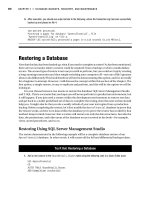
position. Figure 10-1 shows an image of a height map.
Figure 10-1. An example of a height map
265
CHAPTER 10
9241CH10.qxd 3/20/08 10:17 AM Page 265
To build a terrain from a height map, you first need to build a vertex grid with the
same dimensions as the height map, and then use the height value of each point (pixel)
on the height map as the height of a vertex on the vertex grid. For example, you can use a
height map with a 6
✕ 6 pixel resolution to displace the height of each vertex in a 6 ✕ 6
vertex grid.
Besides its position, each vertex on the grid contains other attributes needed for ren-
dering, such as normal and texture coordinate. Figure 10-2 illustrates a vertex grid with
6
✕ 6 vertices created over the world plane XZ, where the height of each vertex is relative
to the world’s Y axis.
Figure 10-2. A 6 ✕ 6 ver
tex grid created over the XZ plane
In a vertex grid you should define a distance between each pair of vertices (vertically
and horizontally). This distance is represented by the “Block Scale” in Figure 10-2. A small
distance between the vertices allows smooth transitions between the vertices’ heights
over the vertex grid but reduces the grid size, while a big distance between the vertices
increases the grid size but can yield sharp transitions between the vertices’ heights. This
way, if the distance between each pair of vertices (vertically and horizontally) is 1 meter,
the total size of the generated terrain will be 255
✕ 255 meters.
As the terrain’s height map is usually stored in 8-bit images, its height values vary
between 0 and 255, where 0 (black color) represents the lowest possible height for a
vertex and 255 (white color) represents the highest possible height. You can raise this
interval using a scale factor, which is multiplied by the default height value, increasing its
range. This provides a bigger height interval, but with less precision between the values.
CHAPTER 10 ■ GENERATING A TERRAIN266
9241CH10.qxd 3/20/08 10:17 AM Page 266
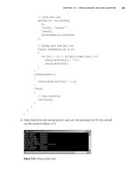
Figure 10-3 shows a 3-D terrain built from the height map of Figure 10-1, rendered in
wireframe (up) and solid (low).
Note that for the rendered terrain shown in Figure 10-3, the normal and the texture
coordinate were calculated for each vertex, allowing correct illumination and texturing of
the terrain.
Figure 10-3. T
err
ain gener
ated fr
om the height map in Figure 10-1 in wireframe and solid
r
endering
Generating a Height Map
You can build or obtain height maps in different ways. You can find different kinds of
height maps all over the Internet, including height maps of real places (cities, and so on).
Because height maps are grayscale images, you can use any image editor tool to build or
CHAPTER 10 ■ GENERATING A TERRAIN 267
9241CH10.qxd 3/20/08 10:17 AM Page 267
edit your own height maps. Also, some tools allow procedural generation of the terrain’s
height map from user-defined parameters.
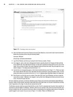
One of the simplest and fastest ways to build height maps is through the use of pro-
cedural generation tools such as Terragen (
/>Terragen allows the generation of a height map from various user-defined parameters,
such as terrain size, realism, smoothing, glaciation, and canyonism. One advantage of
Terragen is that you can use it freely for noncommercial applications. An artist can also
refine the height map generated from Terragen at a later time.
Another tool you can use to create height maps is EarthSculptor (
http://www.
earthsculptor.com/). EarthSculptor has some internal tools for 3-D modeling of terrains,
and it allows saving the terrain model as a height map.
Height Map File Format
The height map file format you’ll use is the RAW format. This format is easy to read
because it doesn’t have a header with image information such as image type and size.
The RAW files are simple binary files that only contain data about the height of the ter-
rain. In an 8-bit height map, each byte inside the RAW file represents the height of a
vertex.
Terrain Class
In this section you’ll create the class to handle the terrain, named Terrain class, where
you’ll initially create methods to load a height map, generate its 3-D mesh, and draw it.
Further, you’ll add new methods to this class, used to query the terrain’s height at a point
and check for collisions.
Loading the Terrain Height Map
The first
step to gener
ate the terr
ain is to r
ead its data fr
om a height map
. As the height
map is stor
ed as a RA
W file
, y
ou can use a
FileStream to r
ead its data and stor
e it in a
byte
arr
ay
. N
otice that because the height map doesn
’
t have a header, you need to know its
siz
e
, and it must match with the v
er
tex
’s grid size. You can use the following code to read
and stor
e the height map data:
// Open a height map file
FileStream fileStream = File.OpenRead(heightmapFileName);
int heightmapSize = vertexCountX * vertexCountZ;
CHAPTER 10 ■ GENERATING A TERRAIN268
9241CH10.qxd 3/20/08 10:17 AM Page 268