Beginning XNA 2.0 Game Programming From Novice to Professional phần 8 pptx
Bạn đang xem bản rút gọn của tài liệu. Xem và tải ngay bản đầy đủ của tài liệu tại đây (751.53 KB, 45 trang )
Using the service container you can get the camera manager (CameraManager) and
obtain the active camera from it, and you can read the terrain transformation from its
transformation attribute of type Transformation:
// Get the camera manager
cameraManager = Game.Services.GetService(
typeof(CameraManager)) as CameraManager;
// Set the camera view and projection
effect.View = cameraManager.ActiveCamera.View;
effect.Projection = cameraManager.ActiveCamera.Projection;
// Set the terrain transformation
effect.World = transformation.Matrix;
Finally, you configure the terrain material and the textures through the LightMaterial
and TextureMaterial attributes of the TerrainMaterial classes. Following is the code for
the
SetEffectMaterial method:
private void SetEffectMaterial()
{
// Get the light manager
LightManager lightManager = Game.Services.GetService(
typeof(LightManager)) as LightManager;
// Get the first two lights from the light manager
PointLight light0 = lightManager[0] as PointLight;
PointLight light1 = lightManager[1] as PointLight;
// Lights
effect.AmbientLightColor = lightManager.AmbientLightColor;
effect.Light1Position = light0.Position;
effect.Light1Color = light0.Color;
effect.Light2Position = light1.Position;
effect.Light2Color = light1.Color;
// Get the camera manager
cameraManager = Game.Services.GetService(
typeof(CameraManager)) as CameraManager;
// Set the camera view and projection
effect.View = cameraManager.ActiveCamera.View;
effect.Projection = cameraManager.ActiveCamera.Projection;
CHAPTER 10 ■ GENERATING A TERRAIN 289
9241CH10.qxd 3/20/08 10:17 AM Page 289
// Set the terrain transformation
effect.World = transformation.Matrix;
// Material
effect.DiffuseColor = terrainMaterial.LightMaterial.DiffuseColor;
effect.SpecularColor = terrainMaterial.LightMaterial.SpecularColor;
effect.SpecularPower = terrainMaterial.LightMaterial.SpecularPower;
// Textures
effect.DiffuseTexture1 = terrainMaterial.DiffuseTexture1.Texture;
effect.DiffuseTexture2 = terrainMaterial.DiffuseTexture2.Texture;
effect.DiffuseTexture3 = terrainMaterial.DiffuseTexture3.Texture;
effect.DiffuseTexture4 = terrainMaterial.DiffuseTexture4.Texture;
effect.NormalMapTexture = terrainMaterial.NormalMapTexture.Texture;
effect.AlphaMapTexture = terrainMaterial.AlphaMapTexture.Texture;
// Textures UVs
effect.TextureUV1Tile = terrainMaterial.DiffuseTexture1.UVTile;
effect.TextureUV2Tile = terrainMaterial.DiffuseTexture2.UVTile;
effect.TextureUV3Tile = terrainMaterial.DiffuseTexture3.UVTile;
effect.TextureUV4Tile = terrainMaterial.DiffuseTexture4.UVTile;
effect.TextureUVNormalTile = material.NormalMapTexture.UVTile;
}
Drawing the Terrain
To draw the terrain, you initially need to call the SetEffectMaterial method, which con-
figures the terrain effect. Then you set the terrain’s vertex buffer, the index buffers, and
the vertex declaration on the graphics device. You use the vertex declaration to inform
the graphics device about the vertex format you’re using, so that it can correctly process
the vertices:
// Set mesh vertex and index buffer
GraphicsDevice.Vertices[0].SetSource(vb, 0,
VertexPositionNormalTangentBinormal.SizeInBytes);
GraphicsDevice.Indices = ib;
// Set the vertex declaration
GraphicsDevice.VertexDeclaration = new VertexDeclaration(GraphicsDevice,
VertexPositionNormalTangentBinormal.VertexElements);
CHAPTER 10 ■ GENERATING A TERRAIN290
9241CH10.qxd 3/20/08 10:17 AM Page 290
The next step is to begin the effects and go over all the effects’ passes, drawing the
terrain for each pass. To draw the terrain’s mesh, you use the
DrawIndexedPrimitives
method of XNA’s GraphicsDevice. You use this method because you’re drawing a primitive
that has indices. Following is the complete code for the
Draw method from the Terrain
class:
public override void Draw(GameTime time)
{
// Configure TerrainEffect
SetEffectMaterial();
// Set mesh vertex and index buffer
GraphicsDevice.Vertices[0].SetSource(vb, 0,
VertexPositionNormalTangentBinormal.SizeInBytes);
GraphicsDevice.Indices = ib;
// Set the vertex declaration
GraphicsDevice.VertexDeclaration = new VertexDeclaration(GraphicsDevice,
VertexPositionNormalTangentBinormal.VertexElements);
effect.Begin();
// Loop through all effect passes
foreach (EffectPass pass in effect.CurrentTechniquePasses)
{
pass.Begin();
// Draw the mesh
GraphicsDevice.DrawIndexedPrimitives(PrimitiveType.TriangleList,
0, 0, numVertices, 0, numTriangles);
pass.End();
}
effect.End();
}
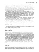
Figure 10-10 shows the final result of the terrain rendering. Notice that the terrain
surface is flat. However, the normal map used adds the detail of a stone pattern over the
surface.
CHAPTER 10 ■ GENERATING A TERRAIN 291
9241CH10.qxd 3/20/08 10:17 AM Page 291
Figure 10-10. Final result of the terrain rendering
Querying the Terrain’s Height
To guarantee that all scene objects remain over the terrain, you should be able to query
the terrain’s height at any position, and then position the objects over the terrain. You can
get the height of a vertex in the terrain from the terrain’s height map, and you can calcu-
late the height of any position over the terrain from the terrain’s vertices.
To query the height of the terrain at an arbitrary world position, you first need to cal-
culate this position r
elative to the terrain’s vertex grid. You can do this by subtracting the
quer
ied world’s position from the initial terrain position, making sure to consider the ter-
rain transformations such as translations. Then you need to know in which quadrant of
the terrain grid the position you are querying is located, which you can do by dividing the
calculated position (relative to the terrain) by the terrain’s block scale.
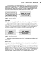
Figure 10-11 shows an object in the world position
(52, 48), where its position in the
terrain grid is
(1, 1). Notice that you aren’t considering the object position over the Y axis
(which represents its height over the terrain), because the terrain is constructed over the
XZ plane, and the value you’re looking for is relative to this axis.
CHAPTER 10 ■ GENERATING A TERRAIN292
9241CH10.qxd 3/20/08 10:17 AM Page 292
Figure 10-11. Object position relative to the terrain grid
The code to calculate the position of an object over the terrain grid follows:
// Get the position relative to the terrain grid
Vector2 positionInGrid = new Vector2(
positionX - (StartPosition.X + Transformation.Translate.X),
positionZ - (StartPosition.Y + Transformation.Translate.Z));
// Calculate the grid position
Vector2 blockPosition = new Vector2(
(int)(positionInGrid.X / blockScale),
(int)(positionInGrid.Y / blockScale));
After you calculate in which quadrant of the grid the position you are querying is,
you should calculate in which triangle of this block it is. You can do this by calculating the
position of the object inside the block and verifying if its position in the X axis is higher
than its position in the Z axis. When the object’s X position is higher than the Z position,
the object will be found on the top triangle; otherwise, if the value is smaller the object
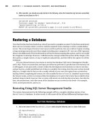
will be found on the bottom triangle, as shown in Figure 10-12.
CHAPTER 10 ■ GENERATING A TERRAIN 293
9241CH10.qxd 3/20/08 10:17 AM Page 293
Figure 10-12. A block in the terrain grid. If the X position inside the block is bigger than the
Z position, the object is in the top triangle. Otherwise, the object is in the bottom triangle.
After finding in which triangle the object is positioned, you can obtain the height of a
position inside this triangle through a linear interpolation of the height of the triangle’s
vertices. Use the following code for the
GetHeight method to calculate the height of a
terrain’s position:
private float GetHeight(float positionX, float positionZ)
{
float height = -999999.0f;
if (heightmap == null) return height;
// Get the position relative to the terrain grid
Vector2 positionInGrid = new Vector2(
positionX - (StartPosition.X + Transformation.Translate.X),
positionZ - (StartPosition.Y + Transformation.Translate.Z));
// Calculate the grid position
Vector2 blockPosition = new Vector2(
(int)(positionInGrid.X / blockScale),
(int)(positionInGrid.Y / blockScale));
// Check if the object is inside the grid
if (blockPosition.X >= 0 && blockPosition.X < (vertexCountX - 1) &&
blockPosition.Y >= 0 && blockPosition.Y < (vertexCountZ - 1))
{
Vector2 blockOffset = new Vector2(
blockPosition.X - (int)blockPosition.X,
blockPosition.Y - (int)blockPosition.Y);
CHAPTER 10 ■ GENERATING A TERRAIN294
9241CH10.qxd 3/20/08 10:17 AM Page 294
// Get the height of the four vertices of the grid block
int vertexIndex = (int)blockPosition.X +
(int)blockPosition.Y * vertexCountX;
float height1 = heightmap[vertexIndex + 1];
float height2 = heightmap[vertexIndex];
float height3 = heightmap[vertexIndex + vertexCountX + 1];
float height4 = heightmap[vertexIndex + vertexCountX];
// Top triangle
float heightIncX, heightIncY;
if (blockOffset.X > blockOffset.Y)
{
heightIncX = height1 - height2;
heightIncY = height3 - height1;
}
// Bottom triangle
else
{
heightIncX = height3 - height4;
heightIncY = height4 - height2;
}
// Linear interpolation to find the height inside the triangle
float lerpHeight = height2 + heightIncX * blockOffset.X +
heightIncY * blockOffset.Y;
height = lerpHeight * heightScale;
}
return height;
}
Notice that you use this method only to ensure that all scene objects are positioned
over the terrain. To produce a realistic interaction between the objects and the terrain
you would need to implement a physics system.
Ray and Terrain Collision
To detect when an object in the scene intercepts a part of the terrain, you need to create
some collision test methods. One useful collision test is between a ray and the terrain.
For example, if an object is moving in the scene, you can trace a ray in the direction in
which this object is moving and get the distance between it and the terrain.
CHAPTER 10 ■ GENERATING A TERRAIN 295
9241CH10.qxd 3/20/08 10:17 AM Page 295
To check the ray and terrain collision, you’ll do a collision test between the ray and
the terrain’s height map, instead of testing the ray against the terrain’s mesh (many trian-
gles). The collision test will be divided in two parts. In the first part, you’ll do a linear
search on the ray until you find a point outside (above) and another inside (below) the
terrain. Then, you’ll perform a binary search between these two points to find the exact
collision point with the terrain. Figure 10-13 illustrates the linear search processes, where
the nearest points outside and inside the terrain are found.
Figure 10-13. Linear search used to find one point inside and another outside the terrain
You can use the following code to perform the linear search on the terrain:
// A good ray step is half of the blockScale
Vector3 rayStep = ray.Direction * blockScale * 0.5f;
Vector3 rayStartPosition = ray.Position;
// Linear search - Loop until find a point inside and outside the terrain
Vector3 lastRayPosition = ray.Position;
ray.Position += rayStep;
float height = GetHeight(ray.Position);
while (ray.Position.Y > height && height >= 0)
{
lastRayPosition = ray.Position;
ray.Position += rayStep;
height = GetHeight(ray.Position);
}
After the linear search, the lastRayPosition variable stores the position outside the
terrain and the
ray variable stores the position inside the terrain. You then need to make a
CHAPTER 10 ■ GENERATING A TERRAIN296
9241CH10.qxd 3/20/08 10:17 AM Page 296
binary search between these two points to find the closest point to the terrain. You make
this search with a fixed number of steps, where 32 steps are enough for a good level of
precision. The code for the binary search follows:
Vector3 startPosition = lastRayPosition;
Vector3 endPosition = ray.Position;
// Binary search with 32 steps. Try to find the exact collision point
for (int i = 0; i < 32; i++)
{
// Binary search pass
Vector3 middlePoint = (startPosition + endPosition) * 0.5f;
if (middlePoint.Y < height) endPosition = middlePoint;
else startPosition = middlePoint;
}
Vector3 collisionPoint = (startPosition + endPosition) * 0.5f;
You then create the Intersects method to check the intersection of a ray and the
terrain. The
Intersects method returns the distance between the ray’s start point and
the terrain’s collision point, and if there is no collision with the terrain, the method will
return
null. Following is the code for the Intersects method of the Terrain class:
public float? Intersects(Ray ray)
{
float? collisionDistance = null;
Vector3 rayStep = ray.Direction * blockScale * 0.5f;
Vector3 rayStartPosition = ray.Position;
// Linear search - Loop until find a point inside and outside the terrain
Vector3 lastRayPosition = ray.Position;
ray.Position += rayStep;
float height = GetHeight(ray.Position);
while (ray.Position.Y > height && height >= 0)
{
lastRayPosition = ray.Position;
ray.Position += rayStep;
height = GetHeight(ray.Position);
}
// If the ray collides with the terrain
if (height >= 0)
{
CHAPTER 10 ■ GENERATING A TERRAIN 297
9241CH10.qxd 3/20/08 10:17 AM Page 297
Vector3 startPosition = lastRayPosition;
Vector3 endPosition = ray.Position;
// Binary search. Find the exact collision point
for (int i = 0; i < 32; i++)
{
// Binary search pass
Vector3 middlePoint = (startPosition + endPosition) * 0.5f;
if (middlePoint.Y < height) endPosition = middlePoint;
else startPosition = middlePoint;
}
Vector3 collisionPoint = (startPosition + endPosition) * 0.5f;
collisionDistance = Vector3.Distance(rayStartPosition, collisionPoint);
}
return collisionDistance;
}
Summary
In this chapter you learned all the steps needed to create a terrain from a height map and
draw it. You first learned what height maps are and how to use them to represent the ter-
rain. Then, you learned how to create a vertex grid to represent the terrain’s mesh and
how to use the height map values to change the height of the vertices of the grid. For each
vertex in the vertex grid, you also learned how to calculate its attributes needed for multi-
texturing, lighting, and normal mapping. Finally, you learned how to create an effect for
the terrain rendering, which uses multitexturing and normal mapping. Besides all this,
you also learned how to create some auxiliary methods to query the height of a position
over the terrain and check the collision between a ray and the terrain.
CHAPTER 10 ■ GENERATING A TERRAIN298
9241CH10.qxd 3/20/08 10:17 AM Page 298
Skeletal Animation
Although the game scenery is mainly composed of static objects, you might want to use
some animated models for animated characters—the player and the nonplayable char-
acters (NPCs)—in your game.You can create animated models in different ways. For
example, in a racing game the car might be an animated model because its wheels rotate
as the vehicle moves. You can easily reproduce this type of animation just by rotating the
car’s wheels over its axis. However, when you need to animate a character (running,
jumping, falling, and so on), the animation process becomes more complex because you
need to modify the character’s mesh. Figure 11-1 shows the animation sequence of a
character walking.
Figure 11-1. I
n this animation of a character walking, the model’s mesh has to be modified
o
ver each frame. Courtesy of Hugo Beyer ().
The animation in Figure 11-1 is composed of five different frames (or keyframes),
where each frame represents a different configuration of the character. Each animation
frame also has a time, which defines when the model configuration needs to be changed.
299
CHAPTER 11
9241CH11.qxd 3/21/08 10:40 AM Page 299
Finally, to be able to loop through the animation, the first animation frame and the last
animation frame must be the same frame or be in sequence.
Types of Animations
There are two main types of animation: keyframed animations and skeletal animations.
Each type of animation is used in different situations and has its advantages and
disadvantages.
Keyframed Animation
In keyframed animation, you store a static model mesh for each frame of the animation.
If you were to animate the model in Figure 11-1, you would have to export four different
static meshes and change the mesh that is drawn in each time frame. This animation is
called
keyframed because only the key frames of the animation are exported. For exam-
ple, in the animation in Figure 11-1, you can have many intermediate frames between
the first and second animation frame, which are used to make the animation smooth.
However, you don’t necessarily need to export them because you can obtain them by
interpolating the first and second frame. For example, in a linear interpolation, the posi-
tion of each vertex in the mesh is interpolated linearly between the first and second
frame.
One of the advantages of the keyframed animation is that it’s fast, because nothing
needs to be calculated during the animation. All the animation frames are stored in
memory, and during the animation you only need to change the model that is drawn
each time. One of the disadvantages of this method is that it’s necessary to store all the
model meshes in memory so they’re quickly drawn. If a model has hundreds of anima-
tion frames, it’s necessary to store its mesh hundreds of times. In a scene with hundreds
of animated models, where all of them share the same animation, the keyframed method
can be useful.
The use of keyfr
amed animated models with XNA is simple
, because XNA
alr
eady has the classes needed to handle static models
.
Therefore, you can treat a
keyframed animation model in XNA as an array of static models, using the
Model class,
for example.
Skeletal Animation
Another way to animate the model is through skeletal animation. In this process, you
need to build a skeleton for the model, composed of some bones, and then connect every
vertex of the mesh to a bone on that skeleton. Therefore, as the skeleton animates the
mesh it’s linked to, it animates too, following the skeleton’s animation.
CHAPTER 11 ■ SKELETAL ANIMATION300
9241CH11.qxd 3/21/08 10:40 AM Page 300
To build the model’s mesh, skeleton, and animations, you can use different modeling
tools that support skeletal (or bone) animation, such as 3ds Max, Maya, Blender, and
others. After you create the model, you also need to export it to a format that supports
skeletal animation. Among the model formats that XNA supports natively, the formats X
(DirectX File) and FBX (Autodesk) support skeletal animation. Notice that the skeletal
animation is also
keyframed, meaning that only the key frames of the skeleton anima-
tions are exported. As in the keyframed animation, you can also interpolate the
animation frames of the skeleton. Figure 11-2 illustrates a model with its mesh and
skeleton.
Figure 11-2. Model with its mesh and skeleton
S
keletal
animation has mor
e advantages over keyframed animation. It allows anima-
tions to be easily blended, allo
wing y
ou to apply differ
ent animations over the model at
the same time
. F
or example
, you could apply two different animations to the model in
F
igur
e 11-2, where one animation would make the model walk and another animation
CHAPTER 11 ■ SKELETAL ANIMATION 301
9241CH11.qxd 3/21/08 10:40 AM Page 301
would make the model look around (rotating its neck). Skeletal animation also allows a
bone from one object to be linked to a bone in another object. For example, if you have a
character that wields a sword, you would connect the bone in the sword to the character’s
hand bone, which makes the sword move as the character’s hand moves. Nowadays,
skeletal animation is more widely used than keyframed animation. Keeping that in mind,
we’ll focus on skeletal animations.
XNA doesn’t natively support skeletal animation. Although XNA’s Content Pipeline is
capable of importing models with skeletal animation, the default model processor is only
capable of processing the model’s mesh and skeleton, discarding the model’s animation.
In addition, the export format of the model’s skeleton might not be adequate and opti-
mized to be used during the animation process.
Skeleton and Bone Representation
Before we detail how to work with skeletal animation in XNA, it’s important that you
understand how the skeleton model is constructed and how its bones are represented
and stored.
There are two different ways to store the model’s skeleton. The first one uses bones
and the second uses joints. For example, 3ds Max represents a skeleton using its bones,
while Maya represents a skeleton using its joints. However, when the model is exported
to an XNA-compatible format (X or FBX format) there is no difference between them and
the skeleton is represented by its bones. In this chapter, you’ll use bones to represent and
store the skeleton, where each bone has an initial position and orientation, and the size
of each bone is defined as the distance between its position and the position of a child
bone. This bone representation creates the necessity of having an end bone (of zero size)
to define the end of the skeleton.
The bone’s orientation and position define its configuration. Figure 11-3 illustrates a
skeleton’s arm representation using bones. Notice that it is necessary to have an End
B
one after the H
and B
one to define the hand bone’s size and the end of the skeleton’s
ar
m.
The position and orientation of each bone is related to its ancestor. For example, the
hand’s orientation and position are defined according to the orientation and position
defined by the forearm, which has its orientation and position defined by the upper arm,
repeating the same process until the root bone is reached. With this concept, you can see
that modifying any bone affects all the descendants of this bone. If the left shoulder bone
was moved, all its descendants would be moved too.
To store the skeleton, you need to store the configuration (orientation and position)
of every bone and the hierarchy of these bones inside the skeleton. The hierarchy is
needed to calculate the absolute configuration of a bone at any given time. You can store
the configuration of a bone as a matrix, and the skeleton hierarchy as a list with refer-
ences to the ancestor of each bone.
CHAPTER 11 ■ SKELETAL ANIMATION302
9241CH11.qxd 3/21/08 10:40 AM Page 302
Figure 11-3. Arm bones of a skeleton. The hierarchy begins in the Root Bone and the end is
defined by the End Bone, where each bone is a descendent of the previous bone. All the
bones begin at the position shown by a square, and they end at the next bone’s starting
point (the following square).
Skeletal Animation in XNA
XNA has a well-defined Content Pipeline, which is separated in different layers and pro-
vides importers, processors, compilers (content writers), and readers (content readers)
for the game assets. Because XNA’s Content Pipeline does not have full support for mod-
els with skeletal animation, you need to extend the Content Pipeline, adding support for
skeletal animation. Notice that the Content Pipeline partially supports skeletal anima-
tion, because it can import the skeletal animation data from the X and FBX files, but it
doesn’t process all the skeletal animation data that is imported. Figure 11-4 shows a sim-
plified diagram of the Content Pipeline classes that are used to import, process, compile,
and read model files.
First, the models are imported by their respective content importer, where each
content importer converts the input model’s data to an XNA document object model
(DOM) format. In this way, after the models have been imported, they are all in the same
format and can be processed by their respective content processor, the
ModelProcessor.
The output of the model importers is a root
NodeContent object, which describe a graphics
type that has its own coordinate system and can have children. Two classes extend the
NodeContent class: MeshContent and BoneContent. So, the root NodeContent object output
from a model importer might have some
NodeContent, MeshContent, and BoneContent
childr
en.
CHAPTER 11 ■ SKELETAL ANIMATION 303
9241CH11.qxd 3/21/08 10:40 AM Page 303
Figure 11-4. The XNA Content Pipeline—classes used to import, process, compile, and read
the game models
The ModelProcessor receives as a parameter the root NodeContent object, output by the
model importer, and returns a
ModelContent object. The ModelContent object returned by
the
ModelProcessor has the processed model data, which needs to be stored into an XNB
binary file. To be able to store the
ModelContent object into an XNB file, the ModelContent
and each object inside of it must have its own ContentTypeWriter. The ContentTypeWriter
defines how the data of each object is written into the XNB file. Finally, at runtime the
ContentManager uses a ContentTypeReader for each object to read its data from the XNB
binary file and return a
Model object.
To add support for skeletal animation in XNA, you need to extend the default model
processor, creating a new one capable of processing and storing the model’s skeleton
and animations. Besides that, you need to create some classes to store the skeletal
animation data (model’s skeleton and animations) and some
ContentTypeWriter and
ContentTypeReader classes to write and read this data.
CHAPTER 11 ■ SKELETAL ANIMATION304
9241CH11.qxd 3/21/08 10:40 AM Page 304
Figure 11-5 shows the classes that you need to create to extend the Content Pipeline,
adding support to models with skeletal animation. The classes that you need to create are
marked in red in Figure 11-5.
Figure 11-5. An e
xtension of the Content Pipeline sho
wn in Figure 11-4, which supports
models with skeletal animation
You’ll create the classes used to store the skeletal animation data in a separate
library, because they’ll be used by the animated model processor to store the skeletal
animation data and by the game application to load this data at runtime. To store the
skeletal animation classes, create a new Windows Game Library project named
AnimationModelContentWin. The model processor will use the classes of this library on
the Windows platform to store the skeletal animation data. If your game was targeted
to the Windows platform, this library would also be used to load the skeletal animation
data in runtime.
If you’re targeting the Xbox 360, you need to create one more project: an Xbox 360
Game Library named
AnimationModelContentXbox. This library contains the same files as
the
AnimationModelContentWin library, but Xbox 360 applications use it to load the skeletal
CHAPTER 11 ■ SKELETAL ANIMATION 305
9241CH11.qxd 3/21/08 10:40 AM Page 305
animation at runtime. You need the AnimationModelContentWin project even if you’re tar-
geting the Xbox 360 platform, because the original model files are imported and
processed on the Windows platform, needing a Windows library to store the model data.
You’ll create three different classes to store the skeletal animation data:
Keyframe,
AnimationData, and AnimatedModelData. The Keyframe class stores an animation frame of
a skeletal animation, where each animation frame stores a new configuration for a
bone in the skeleton. The
AnimationData class stores an array of keyframes, which
compose a complete animation (such as running, jumping, and so on). Finally, the
AnimatedModelData class stores the model skeleton (bones and hierarchy) and an array
of type
AnimatedModelData, containing all the model animations.
Keyframe Class
The Keyframe class is responsible for storing an animation frame of a bone in the skeleton.
An animation frame must have a reference for the animated bone, the new configuration
(position and orientation) of the referenced bone, and the time in which this new config-
uration should be applied. Notice that you use the keyframes to modify the original bone
configuration, changing its current configuration to a new one. You store the bone con-
figuration as a matrix using XNA’s
Matrix class, and you store the animation time (the
time in which this keyframe should be applied) as a
TimeSpan.
In the
AnimatedModelData class you store the model’s skeleton as an array of bones,
which is constructed through a depth traverse of the model’s skeleton. So, you can store
the reference for the bone that will be animated as an integer that represents the index
of the bone in the
bones array of the AnimatedModelData class. The Keyframe class code
follows:
public class Keyframe : IComparable
{
int boneIndex;
TimeSpan time;
Matrix transform;
// Properties
public TimeSpan Time
{
get { return time; }
set { time = value; }
}
public int Bone
{
get { return boneIndex; }
CHAPTER 11 ■ SKELETAL ANIMATION306
9241CH11.qxd 3/21/08 10:40 AM Page 306
set { boneIndex = value; }
}
public Matrix Transform
{
get { return transform; }
set { transform = value; }
}
public Keyframe(TimeSpan time, int boneIndex, Matrix transform)
{
this.time = time;
this.boneIndex = boneIndex;
this.transform = transform;
}
public int CompareTo(object obj)
{
Keyframe keyframe = obj as Keyframe;
if (obj == null)
throw new ArgumentException("Object is not a Keyframe.");
return time.CompareTo(keyframe.Time);
}
}
In the Keyframe class, you’re implementing the interface IComparable to be able to
compare
Keyframe objects. The Keyframe objects are compared based on their time: their
time attribute. You’ll use this comparison further to sort the keyframes according to their
time frame.
AnimationData Class
The AnimationData class is responsible for storing a complete model animation (such as
running, jumping, and so on). You store each animation as an array of type
Keyframe, and
besides its keyframes you also store other useful data such as the animation name and
duration. The code for the
AnimationData class follows:
public class AnimationData
{
string name;
TimeSpan duration;
Keyframe[] keyframes;
CHAPTER 11 ■ SKELETAL ANIMATION 307
9241CH11.qxd 3/21/08 10:40 AM Page 307
public string Name
{
get { return name; }
set { name = value; }
}
public TimeSpan Duration
{
get { return duration; }
set { duration = value; }
}
public Keyframe[] Keyframes
{
get { return keyframes; }
set { keyframes = value; }
}
public AnimationData(string name, TimeSpan duration,
Keyframe[] keyframes)
{
this.name = name;
this.duration = duration;
this.keyframes = keyframes;
}
}
AnimatedModelData Class
The AnimatedModelData class is responsible for storing the model’s skeleton and anima-
tions. You store the model skeleton as an array of bones, where each bone is represented
as a matrix. You construct the bone array through a depth traverse of the model’s skele-
ton. The depth traversal starts in the root bone of the skeleton and goes to the deepest
bone. When it finds the deepest bone in a path, the traversal comes back and tries to find
another possible path, then travels to the deepest bone again. For example, a depth tra-
verse of the hierarchy of Figure 11-6 returns the array Root Bone, Neck, Left Shoulder,
Left Forearm, Left Hand, Left End Bone, Right Shoulder, Right Forearm, Right Hand, and
Right End Bone.
CHAPTER 11 ■ SKELETAL ANIMATION308
9241CH11.qxd 3/21/08 10:40 AM Page 308
Figure 11-6. An example of a skeleton hierarchy
You store the skeleton’s bones in its bind pose configuration. The bind pose is the
pose in which the bones were linked to the model’s mesh and is the starting pose of any
animation. When the model is not being animated or when the animation starts, all the
model’s bones are found in the bind pose.
In the
AnimatedModelData class, you should create two attributes of type XNA Matrix
array for storing the skeleton’s bones, one attribute of type int array for storing the skele-
ton’s bones hierarchy, and one attribute of type
AnimationData array for storing the
model’s animation. The
AnimatedModelData class code follows:
public class AnimatedModelData
{
Matrix[] bonesBindPose;
Matrix[] bonesInverseBindPose;
int[] bonesParent;
AnimationData[] animations;
// Properties
public int[] BonesParent
{
get { return bonesParent; }
set { bonesParent = value; }
}
public Matrix[] BonesBindPose
{
get { return bonesBindPose; }
set { bonesBindPose = value; }
}
CHAPTER 11 ■ SKELETAL ANIMATION 309
9241CH11.qxd 3/21/08 10:40 AM Page 309
public Matrix[] BonesInverseBindPose
{
get { return bonesInverseBindPose; }
set { bonesInverseBindPose = value; }
}
public AnimationData[] Animations
{
get { return animations; }
set { animations = value; }
}
public AnimatedModelData(Matrix[] bonesBindPose,
Matrix[] bonesInverseBindPose, int[] bonesParent,
AnimationData[] animations)
{
this.bonesParent = bonesParent;
this.bonesBindPose = bonesBindPose;
this.bonesInverseBindPose = bonesInverseBindPose;
this.animations = animations;
}
}
In the AnimatedModelData class, the bonesBindPose attribute stores an array containing
the local configuration (related to its ancestor) of each skeleton’s bone in its bind pose,
the
bonesInverseBindPose attribute stores an array containing the inverse absolute config-
uration (not related to its ancestor) of each skeleton’s bone in its bind pose, and the
bonesParent attribute stores the index of the parent of each bone. Finally, the animations
attribute stores the model’s animations.
You use the inverse absolute configuration of a bone to transform the vertices that
are linked to this bone from its default coordinate system (the model coordinate system)
to the coordinate system of this bone, needed to animate (transform) the vertices. We’ll
explain this process in more detail in the section “Skeletal Animation Equations.”
Animated Model Processor
Now you need to create a new model processor that extends the default XNA model
processor.You’ll use this new processor to process the animated models, extract their
skeleton and animations, and store them as an
AnimatedModelData object.
To create the new model processor you should create a new Content Pipeline Exten-
sion Library project named
AnimatedModelProcessorWin. The Content Pipeline Extension
CHAPTER 11 ■ SKELETAL ANIMATION310
9241CH11.qxd 3/21/08 10:40 AM Page 310
Library project comes with a new content processor class, and automatically adds the
Content Pipeline assembly (
Microsoft.Xna.Framework.Content.Pipeline) to the project.
Because you’re going to use the
AnimatedModelContentWin library (that you created in the
last section) to store the animation data, you need to add its assembly to the project too.
Following is the code for the new content processor class that is created with the Content
Pipeline Extension project:
[ContentProcessor]
public class ContentProcessor1 : ContentProcessor<TInput, TOutput>
{
public override TOutput Process(TInput input,
ContentProcessorContext context)
{
// TODO
throw new NotImplementedException();
}
}
The default content processor class extends the ContentProcessor class, which is the
base class for any Content Pipeline processor, and it’s used to process an object of the
type
TInput outputting a new object of the type TOutput. Because you aren’t interested in
creating a new content processor but in extending the features of an existing one, you
must extend an existing content processor instead of the
ContentProcessor class. In this
case, you’ll extend XNA’s
ModelProcessor class, which is the default model processor class.
Also, you’re going to rename your new content processor class to
AnimatedModelProcessor.
Following is the base structure of your new model processor—the
AnimatedModelProcessor
class:
[ContentProcessor]
public class AnimatedModelProcessor : ModelProcessor
{
public static string TEXTURES_PATH = "Textures/";
public static string EFFECTS_PATH = "Effects/";
public static string EFFECT_FILENAME = "AnimatedModel.fx";
public override ModelContent Process(NodeContent input,
ContentProcessorContext context)
{
}
CHAPTER 11 ■ SKELETAL ANIMATION 311
9241CH11.qxd 3/21/08 10:40 AM Page 311
protected override MaterialContent ConvertMaterial(
MaterialContent material, ContentProcessorContext context)
{
}
}
The ModelProcessor class has many methods that you can overwrite, where you only
need to overwrite the
Process and ConvertMaterial methods to process the animated
models. The main method called to process a model is the
Process method. This method
needs to convert a
NodeContent object—which has the meshes, skeleton, and animations
of the model—into a
ModelContent object—which stores the data for an XNA Model object.
Besides the
Process method, the ConvertMaterial method is called to process the model’s
materials.
Overwriting the Default Process Method
In this section you’ll overwrite the Process method of the ModelProcessor class, which is
called to process the model. Also, you’ll create two new methods to extract the model’s
skeleton and animations: the
ExtractSkeletonAndAnimations method and the
ExtractAnimations method, where the ExtractAnimations method is called inside the
ExtractSkeletonAndAnimations method. Following is the code for the overwritten
Process method:
public override ModelContent Process(NodeContent input,
ContentProcessorContext context)
{
// Process the model with the default processor
ModelContent model = base.Process(input, context);
// Now extract the model skeleton and all its animations
AnimatedModelData animatedModelData =
ExtractSkeletonAndAnimations(input, context);
// Stores the skeletal animation data in the model
Dictionary<string, object> dictionary = new Dictionary<string, object>();
dictionary.Add("AnimatedModelData", animatedModelData);
model.Tag = dictionary;
return model;
}
CHAPTER 11 ■ SKELETAL ANIMATION312
9241CH11.qxd 3/21/08 10:40 AM Page 312
At the beginning of the Process method, you call the Process method of the base
class, the
ModelProcessor. Then you call the ExtractSkeletonAndAnimations method, which
processes the input
NodeContent and returns an AnimatedModelData object containing the
model’s skeleton and animations. Finally, you create a dictionary that maps a string into
an object, add the
AnimatedModelData to this dictionary, and set it in the Tag property of
the resulting
ModelContent object. XNA’s Model class has a Tag property that enables cus-
tom user data to be added to the model. Using a dictionary as the
Tag property, you can
add many different custom objects to XNA’s
Model class, and query for any of them at run-
time using a string.
Notice that the data you set in the
Tag property of the ModelContent object is stored
together with the model data in a binary XNB file. This data is retrieved when the model
is loaded using the content manager.
Extracting the Model’s Skeleton
The ExtractSkeletonAndAnimations method receives the root NodeContent object as input,
which might have
MeshContent and BoneContent objects as its children, as described
before. To extract the model’s skeleton, you first need to find the root bone of the skeleton
inside the root
NodeContent, then you need to depth traverse the skeleton, creating a list of
bones. XNA’s
MeshHelper class provides some methods to help you in this process:
// Find the root bone node
BoneContent skeleton = MeshHelper.FindSkeleton(input);
// Transform the hierarchy in a list (depth traversal)
IList<BoneContent> boneList = MeshHelper.FlattenSkeleton(skeleton);
You can find the root bone of the skeleton using the FindSkeleton method of the
MeshHelper class. Then you need to transform the skeleton tree into a list, using a deep
search. You do this using the
FlattenSkeleton method of the MeshHelper class. The result
is a list of bones, where each bone is an object of the
BoneContent class. Notice that the
bones in this list are in the same order as they are indexed by the mesh’s vertices.
For each bone in the created list, you want to store its local configuration in the bind
pose, its inverse absolute configuration in the bind pose, and the index of its parent.
You can read the local and absolute configuration of a bone from the Transform and
AbsoluteTransform properties of the BoneContent objects, and you can calculate the inverse
absolute configuration of the bone using the
Invert method of XNA’s Matrix class:
bonesBindPose[i] = boneList[i].Transform;
bonesInverseBindPose[i] = Matrix.Invert(boneList[i].AbsoluteTransform);
CHAPTER 11 ■ SKELETAL ANIMATION 313
9241CH11.qxd 3/21/08 10:40 AM Page 313