OBJECT-ORIENTED ANALYSIS AND DESIGNWith application 2nd phần 4 potx
Bạn đang xem bản rút gọn của tài liệu. Xem và tải ngay bản đầy đủ của tài liệu tại đây (402.19 KB, 54 trang )
Chapter 4: Classification 155
perceive to be important about the domain" [39]. Moore and Bailin suggest the following
steps in domain analysis:
• "Construct a strawman generic model of the domain by consulting with domain
experts.
• Examine existing systems within the domain and represent this understanding in a
common format.
• Identify similarities and differences between the systems by consulting with domain
experts.
• Refine the generic model to accommodate existing systems" [40].
Domain analysis may be applied across similar applications (vertical domain analysis), as
well as to related parts of the same application (horizontal domain analysis). For example,
when starting to design a new patient-monitoring system, it is reasonable to survey the
architecture of existing systems to understand what key abstractions and mechanisms were
previously employed and to evaluate which were useful and which were not. Similarly, an
accounting system must provide many different kinds of reports. By considering these
reports within the same application as a single domain, a domain analysis can lead the
developer to an understanding of the key abstractions and mechanisms that serve all the
different kinds of reports. The resulting classes and objects reflect a set of key abstractions
and mechanisms generalized to the immediate report-generation problem; therefore, the
resulting design is likely to be simpler than if each report had been analyzed and designed
separately.
Who exactly is a domain expert? Often, a domain expert is simply a user, such as a train
engineer or dispatcher in a railway system, or a nurse or doctor in a hospital. A domain
expert need not be a software engineer; more commonly, he or she is simply a person who is
intimately familiar with all the elements of a particular problem. A domain expert speaks the
vocabulary of the problem domain.
Some managers may be concerned with the idea of direct communication between developers
and end users (for some, even more frightening is the prospect of letting an end user see a
developer!). For highly complex systems, domain analysis may involve a formal process,
using the resources of multiple domain experts and developers over a period of many
months. In practice, such a formal analysis is rarely necessary. Often, all it takes to clear up a
design problem is a brief meeting between a domain expert and a developer. It is truly
amazing to see what a little bit of domain knowledge can do to assist a developer in making
intelligent design decisions. Indeed, we find it highly useful to have many such meetings
throughout the design of a system. Domain analysis is rarely a monolithic activity; it is better
focused if we consciously choose to analyze a little, then design a little.
Use-Case Analysis In isolation, the practices of classical analysis, behavior analysis, and
domain analysis all depend upon a large measure of personal experience on the part of the
analyst. For the majority of development projects, this is unacceptable, because such a process
is neither deterministic nor predictably successful.
Chapter 4: Classification 156
However, there is one practice that can be coupled with all three of these earlier approaches,
to drive the process of analysis in a meaningful way. That practice is use-case analysis, first
formalized by Jacobson. Jacobson defines a use case as "a particular form or pattern or
exemplar of usage, a scenario that begins with some user of the system initiating some
transaction or sequence of interrelated events" [41].
Briefly, we can apply use-case analysis as early as requirements analysis, at which time end
users, other domain experts, and the development team enumerate the scenarios that are
fundamental to the system's operation (we need not elaborate upon these scenarios at first,
we can simply enumerate them). These scenarios collectively describe the system functions of
the application. Analysis then proceeds by a study of each scenario, using storyboarding
techniques similar to practices in the television and movie industry [42]. As the team walks
through each scenario, they must identify the objects that participate in the scenario, the
responsibilities of each object, and how those objects collaborate with other objects, in terms
of the operations each invokes upon the other. In this manner, the team is forced to craft a
clear separation of concerns among all abstractions. As the development process continues,
these initial scenarios are expanded to consider exceptional conditions as well as secondary
system behaviors (what Goldstein and Alger speak of as peripheral topics [43]). The results
from these secondary scenarios either introduce new abstractions or add, modify, or reassign
the responsibilities of existing abstractions. As we will discuss further in Chapter 6, scenarios
also serve as the basis of system tests.
CRC Cards CRC cards have emerged as a simple yet marvelously effective way to analyze
scenarios.
38
First proposed by Beck and Cunningham as a tool for teaching object-oriented
programming [44], CRC cards have proven to be a useful development tool that facilitates
brainstorming and enhances communication among developers. A CRC card is nothing more
than a 3x5 index card,
39
upon which the analyst writes - in pencil - the name of a class (at the
top of the card), its responsibilities (on one half of the card) and its collaborators (on the other
half of the card). One card is created for each class identified as relevant to the scenario. As
the team walks through the scenario, they may assign new responsibilities to an existing
class, group certain responsibilities to form a new class, or (most commonly) divide the
responsibilities of one class into more fine-grained ones, and perhaps distribute these
responsibilities to a different class.
CRC cards can be spatially arranged to represent patterns of collaboration. As viewed from
the dynamic semantics of the scenario, the cards are arranged to show the flow of messages
among prototypical instances of each class; as viewed from the static semantics of the
scenario, the cards are arranged to represent generalization/specialization or aggregation
hierarchies among the classes.
38
CRC stands for Class/Responsibilities/Collaborators
39
lf your software development budget can handle it, buy 5x7 cards. Cards with lines are nice, a sprinkling of
colored cards shows that you are a very cool developer.
Chapter 4: Classification 157
Informal English Description A radical alternative to classical object-oriented analysis was
first proposed by Abbott, who suggests writing an English description of the problem (or a
part of a problem) and then underlining the nouns and verbs [45]. The nouns represent
candidate objects, and the verbs represent candidate operations upon them. This technique
lends itself to automation, and such a system has been built at the Tokyo Institute of
Technology and at Fujitsu [46].
Abbott's approach is useful because it is simple and because it forces the developer to work in
the vocabulary of the problem space. However, it is by no means a rigorous approach, and it
definitely does not scale well to anything beyond fairly trivial problems. Human language is
a terribly imprecise vehicle of expression, so the quality of the resulting list of objects and
operations depends upon the writing skill of its author. Furthermore, any noun can be
verbed, and any verb can be nouned; therefore, it is easy to skew the candidate list to
emphasize either objects or operations.
Structured Analysis A second alternative to classical object-oriented analysis uses the
products of structured analysis as a front end to object-oriented design. This technique is
appealing only because a large number of analysts are skilled in structured analysis, and
many CASE tools exist that support the automation of these methods. Personally, we
discourage the use of structured analysis as a front end to object-oriented design, but for
some organizations, it is the only pragmatic alternative.
In this approach, we start with an essential model of the system, as described by data flow
diagrams and the other products of structured analysis. These diagrams provide us with a
reasonably formal model of the problem. From this model, we may proceed to identify the
meaningful classes and objects in our problem domain in three different ways.
McMenamin and Palmer suggest starting with an analysis of the data dictionary and
proceeding to analyze the model’s context diagram. As they state, "With your list of essential
data elements, think about what they tell you or what they describe. lf they were adjectives in
a sentence, for instance, what nouns would they modify? The answers to this question make
up the list of candidate objects" [47]. These candidate objects typically derive from the
surrounding environment, from the essential inputs and outputs, and from the products,
services, and other resources managed by the system.
The next two techniques involve analyzing individual data flow diagrams. Given a particular
data flow diagram (using the terminology of Ward/Mellor [48]), candidate objects may be
derived from the following:
• External entities
• Data stores
• Control stores
• Control transformations
Candidate classes derive from two sources:
Chapter 4: Classification 158
• Data flows
• Control flows
This leaves us with data transformations, which we assign either as operations upon existing
objects or as the behavior of an object we invent to serve as the agent responsible for this
transformation.
Seidewitz and Stark suggest another technique, which they call abstraction analysis.
Abstraction analysis focuses upon the identification of central entities, which are similar in
nature to central transforms in structured design. As they state, "In structured analysis, input
and output data are examined and followed inwards until they reach the highest level of
abstraction. The processes between the inputs and the outputs form the central transform. In
abstraction analysis a designer does the same, but also examines the central transform to
determine which processes and states represent the best abstract model of what the system
does" [49]. After identifying the central entity in a particular data flow diagram, abstraction
analysis proceeds to identify all the supporting entities by following the afferent and efferent
data flows from the central entity, and grouping the processes and states encountered along
the way. In practice, Seidewitz and Stark have found abstraction analysis a difficult technique
to apply successfully, and as an alternative recommend object-oriented analysis methods [50].
We must emphasize that structured design, as normally coupled with structured analysis, is
entirely orthogonal to the principles of object-oriented design. Our experience indicates that
using structured analysis as a front end to object-oriented design often fails when the
developer is unable to resist the urge of falling back into the abyss of the structured design
mindset. Another very real danger is the fact that many analysts tend to write data flow
diagrams that reflect a design rather than an essential model of the problem. It is
tremendously difficult to build an object-oriented system from a model that is so obviously
biased towards algorithmic decomposition. This is why we prefer object-oriented analysis as
the front end to object-oriented design: there is simply less danger of polluting the design
with preconceived algorithmic notions.
If you must use structured analysis as a front end, for whatever honorable reasons,
40
we
suggest that you stop writing data flow diagrams as soon as they start to smell of a design
instead of an essential model. Also, it is a healthy practice to walk away from the products of
structured analysis once the design is fully underway. Remember that the products of
development, including data flow diagrams, are not ends in themselves; they should be
viewed simply as tools along the way that aid the developer's intellectual comprehension of
the problem and its implementation. One typically writes a data flow diagram and then
invents the mechanisms that implement the desired behavior. Practically speaking, the very
act of design changes the developer's understanding of the problem, making the original
model somewhat obsolete. Keeping the original model up to date with the design is terribly
labor intensive, is not amenable to automation, and, frankly, doesn't add a lot of value. Thus,
40
Political and historical reasons are distinctly not honorable.
Chapter 4: Classification 159
only the products of structured analysis that are at a sufficiendy high level of abstraction
should be retained. They capture an essential model of the problem, and so lend themselves
to any number of different designs.
4.3 Key Abstractions and Mechanisms
Identifying Key Abstractions
Finding Key Abstractions A key abstraction is a class or object that forms part of the
vocabulary of the problem domain. The primary value of identifying such abstractions is that
they give boundaries to our problem; they highlight the things that are in the system and
therefore relevant to our design, and suppress the things that are outside the system and
therefore superfluous. The identification of key abstractions is highly domain-specific. As
Goldberg states, the "appropriate choice of objects depends, of course, on the purposes to
which the application will be put and the granularity of information to be manipulated" [51].
As we mentioned earlier, the identification of key abstractions involves two processes:
discovery and invention. Through discovery, we come to recognize the abstractions used by
domain experts; if the domain expert talks about it, then the abstraction is usually important
[52]. Through invention, we create new classes and objects that are not necessarily part of the
problem domain, but are useful artifacts in the design or implementation. For example, a
customer using an automated teller speaks in terms of accounts, deposits, and withdrawals;
these words are part of the vocabulary of the problem domain. A developer of such a system
uses these same abstractions, but must also introduce new ones, such as databases, screen
managers, lists, queues, and so on. These key abstractions are artifacts of the particular
design, not of the problem domain.
Perhaps the most powerful way to identify key abstractions is to look at the problem or
design and see if there are any abstractions that are similar to the classes and objects that
already exist. As we will discuss further in Chapter 6, in the absence of such reusable
abstractions, we recommend the use of scenarios to drive the process of identifying classes
and objects.
Refining Key Abstractions Once we identify a certain key abstraction as a candidate, we
must evaluate it according to the metrics described in the previous chapter. As Stroustrup
suggests, "Often this means that the programmer must focus on the questions: how are
objects of this class created? can objects of this class be copied and/or destroyed? what
operations can be done on such objects? If there are no good answers to such questions, the
concept probably wasn't 'clean' in the first place, and it might be a good idea to think a bit
more about the problem and the proposed solution instead of immediately starting to 'code
around' the problems" [53].
Chapter 4: Classification 160
Given a new abstraction, we must place it in the context of the existing class and object
hierarchies we have designed. Practically speaking, this is
Classes and objects should be at the right level of abstraction: neither too high nor too low.
neither a top-down nor a bottom-up activity. As Halbert and O'Brien observe, "You do not
always design types in a type hierarchy by starting with a supertype and then creating the
subtypes. Frequently, you create several seemingly disparate types, realize they are related,
and then factor out their common characteristics into one or more supertypes . . . several
passes up and down are usually required to produce a complete and correct program design"
[54]. This is not a license to hack, but an observation, based upon experience, that object-
oriented design is both incremental and iterative. Stroustrup makes a similar observation
when he notes that "the most common reorganizations of a class hierarchy are factoring the
common part of two classes into a new class and splitting a class into two new ones" [55].
Placing classes and objects at the right levels of abstraction is difficult. Sometimes we may
find a general subclass, and so may choose to move it up in the class structure, thus
increasing the degree of sharing. This is called class promotion [56]. Similarly, we may find a
class to be too general, thus making inheritance by a subclass difficult because of the large
semantic gap. This is called a grainsize conflict [57]. In either case, we strive to identify
cohesive and loosely coupled abstractions, so as to mitigate these two situations.
Chapter 4: Classification 161
Naming things properly - so that they reflect their semantics - is often treated lightly by most
developers, yet is important in capturing the essence of the abstractions we are describing.
Software should be written as carefully as English prose, with consideration given to the
reader as well as to the computer [58]. Consider for a moment all the names we may need just
to identify a single object: we have the name of the object itself, the name of its class, and the
name of the module in which that class is declared. Multiply this by thousands of objects and
possibly hundreds of classes, and you have a very real problem.
We offer the following suggestions:
• Objects should be named with proper noun phrases, such as theSensor or just simply
shape.
• Classes should be named with common noun phrases, such as Sensors or Shapes.
• Modifier operations should be named with active verb phrases, such as draw or moveLeft.
• Selector operations should imply a query or be named with verbs the form "to be,"
such as extentOf or is0pen.
• The use of underscores and styles of capitalization are largely matters of personal taste.
No matter which cosmetic style you use, at least have your programs be self-
consistent.
Identifying Mechanisms
Finding Mechanisms In the previous chapter, we used the term mechanism to describe any
structure whereby objects collaborate to provide some behavior that satisfies a requirement of
the problem. Whereas the design of a class embodies the knowledge of how individual
objects behave, a mechanism is a design decision about how collections of objects cooperate.
Mechanisms thus represent patterns of behavior.
For example, consider a system requirement for an automobile: pushing the accelerator
should cause the engine to run faster, and releasing the accelerator should cause the engine to
run slower. How this actually comes about is absolutely immaterial to the driver. Any
mechanism may be employed as long as it delivers the required behavior, and thus which
mechanism is selected is largely a matter of design choice. More specifically, any of the
following designs might be considered:
• A mechanical linkage from the accelerator to the carburetor (the most common
mechanism).
• An electronic linkage from a pressure sensor below the accelerator to a computer that
controls the carburetor (a drive-by-wire mechanism).
• No linkage exists; the gas tank is placed on the roof of the car, and gravity causes fuel
to flow to the engine. Its rate of flow is regulated by a clip around the fuel line;
pushing on the accelerator pedal eases tension on the clip, causing the fuel to flow
faster (a low-cost mechanism).
Chapter 4: Classification 162
Mechanisms are the means whereby objects collaborate to provide some higher-level behavior.
Which mechanism a developer chooses from a set of alternatives is most often a result of
other factors, such as cost, reliability, manufacturability, and safety.
Just as it is rude for a client to violate the interface of another object, so it is socially
unacceptable for objects to step outside the boundaries of the rules of behavior dictated by a
particular mechanism. Indeed, it would be surprising for a driver if stepping -on-an
accelerator turned on the car's lights instead of causing the engine to run faster.
Whereas key abstractions-reflect the vocabulary of the problem domain, mechanisms are the
soul of the design. During the design process, the developer must consider not only the
design of individual classes, but also how instances of these classes work together. Again, the
use of scenarios drives this analysis process. Once a developer decides upon a particular
pattern of collaboration, the work is distributed among many objects by defining suitable
methods in the appropriate classes. Ultimately, the protocol of an individual class
encompasses all the operations required to implement all the behavior and all the
mechanisms associated with each of its instances.
Mechanisms thus represent strategic design decisions, as does the design of a class structure.
In contrast, however, the interface of an individual class is more of a tactical design decision.
These strategic decisions must be made explicitly; otherwise we will end up with a mob of
relatively uncooperative objects, all pushing and shoving to do their work with little regard
for other objects. The most elegant, lean, and fast programs embody carefully engineered
mechanisms.
Mechanisms are actually one in a spectrum of patterns we find in well-structured software
systems. At the low end of the food chain, we have idioms. An idiom is an expression peculiar
to a certain programming language or application culture, representing a generally accepted
convention for use of the language
41
. For example, in CLOS, no programmer would use
underscores in function or variable names, although this is common practice in Ada [59]. Part
of the effort in learning a programming language is learning its idioms, which are usually
passed down as folklore from programmer to programmer. However, as Coplien points out,
idioms play an important role in codifying low-level patterns. He notes that, "many common
programming tasks [are] idiomatic and therefore identifying such idioms allows "using C++
constructs to express functionality outside the language proper, while giving the illusion of
being part of the language" [60].
At the high end of the food chain, we have frameworks. A framework is collection of classes
that provide a set of services for a particular domain; a frame work thus exports a number
41
One defining characteristic of an idiom is that ignoring or violating the idiom has immediate social
consequences: you are branded as a yahoo or, worse, an outsider, unworthy of respect.
Chapter 4: Classification 163
of individual classes and mechanisms, which clients can use or adapt. As we will discuss in
Chapter 9, frameworks represent reuse in the large.
Whereas idioms are part of a programming culture, frameworks are often the product of
commercial ventures. For example, Apple's MacApp (and its successor, Bedrock) are both
application frameworks, written in C++, for building applications that conform to Macintosh
user interface standards. Similarly, the Microsoft Foundation Library and Borland's
ObjectWindows library are frameworks for building applications that conform to the
Windows user interface standards.
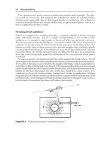
Examples of Mechanisms Consider the drawing mechanism commonly used in graphical
user interfaces. Several objects must collaborate to present an image to a user: a window, a
view, the model being viewed, and some client that knows when (but not how) to display this
model. The client first tells the window to draw itself. Since it may encompass several
subviews, the window next tells each of its subviews to draw themselves. Each subview in
turn tells its model to draw itself, ultimately resulting in an image shown to the user. In this
mechanism, the model is entirely decoupled from the window and view in which it is
presented views can send messages to models, but models cannot send messages to views.
Smalltalk uses a variation of this mechanism, and calls it the model-view-controller (MVC)
paradigm [61]. A similar mechanism is employed in almost every object-oriented graphical
user interface framework.
Mechanisms thus represent a level of reuse that is higher than the reuse of individual classes.
For example, the MVC paradigm is used extensively in the smalltalk user interface. The MVC
paradigm in turn builds on another mechanism, the dependency mechanism, which is
embodied in the behavior of the- Smalltalk base class Model, and thus pervades much of the
Smalltalk class library.
Examples of mechanisms may be found in virtually every domain. For example, the structure
of an operating system may be described at the highest level of abstraction according to the
mechanism used to dispatch programs. A particular design might be monolithic (such as MS-
DOS), or it may employ a kernel (such as UNIX) or a process hierarchy (as in the THE
operating system) [62]. In artificial intelligence, a variety of mechanisms have been explored
for the design o reasoning systems. One of the most widely used paradigms is the blackboard
mechanism, in which individual knowledge sources independently update a blackboard.
There is no central control in such a mechanism, but any change to the blackboard may
trigger an agent to explore some new problem-solving path [63]. Coad has similarly identified
a number of common mechanisms in object-oriented systems, including patterns of time
association, event logging, and broadcasting [64]. In each case, these mechanisms manifest
themselves not as individual classes, but as the structure of collaborating classes.
This completes our study of classification and of the concepts that serve as the foundation of
object-oriented design. The next three chapters focus on the method itself, including its
notation, process, and pragmatics.
Chapter 4: Classification 164
Summary
• The identification of classes and objects is the fundamental issue in object oriented
design; identification involves both discovery and invention.
• Classification is fundamentally a problem of clustering.
• Classification is an incremental and iterative process, made difficult because a given
set of objects may be classified in many equally proper ways.
• The three approaches to classification include classical categorization (classification by
properties), conceptual clustering (classification by concepts), and prototype theory
(classification by association with a prototype).
• Scenarios are a powerful tool of object-oriented analysis; and can be used to drive the
process of classical analysis, behavior analysis, and domain analysis.
• Key abstractions reflect the vocabulary of the problem domain and may either be
discovered from the problem domain, or invented as part of the design.
• Mechanisms denote strategic design decisions regarding the collaborative activity of
many different kinds of objects.
Further Readings
The problem of classification is timeless. in his work tifled Statesman, Plato introduces the
classical approach to categorization, through which objects with similar properties are
grouped. In Categories Aristotle picks up this theme and analyzes the differences between
classes and objects. Several centuries later, Aquinas, in Summa Theologica, and then
Descartes, in Rules for the Direction of the Mind, ponder the philosophy of classification.
Contemporary objectivist philosophers include Rand [1 1979].
Alternatives to the objectivist view of the world are discussed in Lakoff [1 1980] and
Go1dstein and Alger [C 1992]
Classification is an essential human skill. Theories regarding its acquisition during early
childhood development were pioneered by Piaget, and are summarized by Maier [A
1969]. Lefrancois [A 1977] offers a very readable introduction to these ideas and provides
an excellent discourse on children's acquisition of the object concept.
Cognitive scientists have explored the problems of classification in great detail. Newell and
Simon [A 1972] provide an unmatched source of material regarding human classification
skills. More general information may be found in Simon [A 1982], Hol`stad.ter [1 1979],
Siegler and Richards [A 1982], and Stillings, Feinstein, Garfield, Rissland, Rosenbaum,
Weisler, and. Baker~Ward [A 1987]. Lakoff [A 1987], a linguist, offers insights into the
ways different human languages have evolved to cope with the problems of classification
and what this reveals about the mind. Minksy [A 1986] approaches this subject from the
opposite direction, starting with a theory regarding the structure of the mind.
Chapter 4: Classification 165
Conceptual clustering, an approach to knowledge representation through classification, is
described in detail by Michalski and Stepp [A 1983, 1986], Peckham and Maryanski U
1988], and Sowa [A 1984]. Domain analysis, an approach to finding key abstractions and
mechanisms by examining the vocabulary of the problem domain, is described in the
comprehensive collection of papers by Prieto-Diaz and Arango [A 1991]. Iscoe [B 1988] has
made several important contributions to this field. Additional infonnation may be found
in iscoe, Browne, and Weth [13 1989], Moore and Bailin [13 1988], and Arango [B 1989].
Intelligent classification often requires looking at the world in innovative ways, and these
skills can be taught (or, at least, encouraged). Von0ech [1 1990] suggests some paths to
creativity. Coad [A 1993] has a developed a board game (the Object Game) that fosters
skills in class and object identification.
Although the field. is still in its infancy, some very promising work is being carried out in the
cataloging of patterns in software systems, giving rise to a taxonomy of idioms,
mechanisms, and frameworks. Interesting references include Coplien [G 1992], Coad [A
1992], johnson [A 1992], Shaw [A 1989, 1990, 1991], Wirfs-Brock [C 1991]. Alexander's
influential work [1 1979] applies patterns to the field of building architecture and city
planning.
Mathematicians have attempted to devise empirical approaches to classification, leading to
what is called measurement tileory. Stevens [A 1946] and Coombs, Raiffa, and Thrall [A
1954] provide the seminal work on this topie.
The Classification Society of North America publishes a jurnal twice a year, containing a
variety of papers on the problems of classification.
THE SECOND SECTION
THE METHOD
Which innovation leads to a successful design and which to a
failure is not completely predictable. Each opportunity to design
something new, either bridge or airplane or skyscraper, presents
the engineer with choices that may appear countless. The
engineer may decide to copy as many seemingly good features as
he can from existing designs that have successfully withstood the
forces of man and nature, but he may also decide to improve upon
those aspects of prior designs that appear to be wanting.
HENRY PETROSKI
To Engineer is Human
CHAPTER 5
167
The Notation
The act of drawing a diagram does not constitute analysis or design. A diagram simply
captures a statement of a system's behavior (for analysis), or the vision and details of an
architecture (for design). lf you follow the work of any engineer - software, civil, mechanical,
chemical, architectural, or whatever - you will soon realize that the one and only place that a
system is conceived is in the mind of the designer. As this design unfolds over time, it is often
captured on such high-tech media as white boards, napkins, and the backs of envelopes [1].
Still, having a well-defined and expressive notation is important to the process of software
development. First, a standard notation makes it possible for an analyst or developer to
describe a scenario or formulate an architecture and then unambiguously communicate those
decisions to others. Draw an electrical circuit, and the symbol for a transistor will be
understood by virtually every electrical engineer in the world. Similarly, if an architect in New
York City drafts the plans for a house, a builder in San Francisco will have little trouble
understanding where to place doors, windows, and electrical outlets from the details of the
blueprints. Second, as Whitehead states in his seminal work on mathematics, “By relieving
the brain of all unnecessary work, a good notation sets it free to concentrate on more
advanced problems" [2]. Third, an expressive notation makes it possible to eliminate much of
the tedium of checking the consistency and correctness of these decisions by using
automated tools. As a report by the Defense Science Board states, "Software development is
and always will be a labor-intensive technology Although our machines can do the dog-
work and can help us keep track of our edifices, concept development is the quintessentially
human activity The part of software development that will not go away is the crafting of
conceptual structures; the part that can go away is the labor of expressing them" [3].
Chapter 5: The Notation 168
Figure 5-1
The Models of Object-Oriented Development
5.1 Elements of the Notation
The Need for Multiple Views
It is impossible to capture all the subtle details of a complex software system in just one view.
As Kleyn and Gingrich observe, "One must understand both the structure and the function of
the objects involved. One must understand the taxonomic structure of the class objects, the
inheritance mechanisms used, the individual behaviors of objects, and the dynamic behavior
of the system as a whole. The problem is somewhat analogous to that of viewing a sports
event such as tennis or a football game. Many different camera angles are required to provide
an understanding of the action taking place. Each camera reveals particular aspects of the
action that could not be conveyed by one camera alone" [4].
First introduced in Chapter 1, Figure 5-1 indicates the different models we have found to be
important in object-oriented development. For a given project, the products of analysis and
design are expressed through these models. Collectively, these different models are
semantically rich: they are expressive enough to allow a developer to capture all of the
interesting strategic and tactical decisions one must make during the analysis of a system as
well as during the formulation of its architecture, and they are complete enough to serve as
blueprints for implementation in almost any object-oriented programming language.
The fact that this notation is detailed does not mean that every aspect of it must be used at all
times. In fact, a proper subset of this notation is sufficient to express the semantics of a large
percentage of analysis and design issues; one of our colleagues refers to this subset as the
Booch Lite notation. We will highlight this subset during our presentation of the notation in
this chapter. Why then bother with the detail beyond this subset? Quite simply, such detail is
necessary to express certain important tactical decisions; additionally, some detail exists to
facilitate the creation of forward-engineering and reverse-engineering tools, which provide
integration of front-end CASE tools that support this notation together with software
Chapter 5: The Notation 169
development environments that focus upon manipulating the products of the object-oriented
programming language.
As Weinberg notes, "In other design fields, such as architecture, the rough sketch is the most
frequently used graphic device, and precise detailed drawings are rarely used at all until the
creative part of the design work is finished" [5]. Remember, a notation is only a vehicle for
capturing the reasoning about the behavior and architecture of a system; a notation is not an
end in itself. Therefore, one should apply only those elements of the notation that are
necessary to convey the intended meaning, and nothing more. Just as it is dangerous to
overspecify a set of requirements, so it is dangerous to overspecify a solution to a problem.
For example, on a blueprint, an architect may show the general location of a light switch in a
room, but its exact location will not be established until the construction manager and owner
do an electrical walk-through, after the house has been framed. It would be foolish to specify
the precise three-dimensional coordinates of the light switch on the blueprint (unless, of
course, this was a detail that was functionally important to the owner: perhaps the owner's
family is significantly taller or shorter than average). Thus, if the analysts, designers, and
implementors of a software intensive system are highly skilled and have already established a
close -working relationship, then rough sketches may suffice (although it will still be
necessary to leave a legacy of the architectural vision for the sake of the system's maintainers).
If, on the other hand, the implementors are not quite so skilled, or if the developers are
separated geographically, in time, or by contract, then more detail will be required during the
development process. The notation we present in this chapter covers each of these situations.
Different programming languages sometimes use different terms to express the same concept.
The notation we present in this chapter is largely language-independent, as any good
development notation should be. Of course, some elements of the notation have no parallel in
certain languages and thus should be avoided if that language is to be used for
implementation. For example, free subprograms cannot be declared in Smalltalk, and
therefore class utilities will not in general be used in a system implemented in Smalltalk.
Similarly, C++ does not support metaclasses, and therefore this element of the notation may
be ignored. Also, there is nothing wrong with tailoring this notation in language-specific
ways. For example, the qualification associated with an operation might be tailored for CLOS
to identify primary methods, as well as
:before, :after, and :around methods. Similarly, a tool for
C++ might ignore the notation's class specification, and use C++ header files directly.
The only purpose of this chapter is to describe the syntax and semantics of our notation for
object-oriented analysis and design. We will provide a few small examples of this notation,
using the problem of the hydroponics gardening system that we introduced in Chapter 2.
This current chapter does not explain the process by which we derived these figures; that is
the topic of Chapter 6. In Chapter 7, we discuss the pragmatics of this process, and in
Chapters 8 through 12, we demonstrate the practical application of this notation through a
series of extended application examples.
Chapter 5: The Notation 170
Models and Views
In Chapter 3, we explained the meaning of classes and objects and their relationships. As
Figure 5-1 suggests, we may capture our analysis and design decisions regarding these
classes and objects and their collaborations according to two dimensions: their
logical/physical view, and their static/dynamic view. Both dimensions are necessary to
specify the structure and behavior of an object-oriented system.
For each dimension, we define a number of diagrams that denote a view of a system's
models. In this sense, the system's models denote the "whole truth" about its classes,
relationships, and other entities, and each diagram represents a projection of these models. In
the steady state, all such diagrams must be consistent with the model and therefore among
themselves.
For example, consider an application comprising several hundred classes; the classes form
part of the application's model. It is impossible and in fact unnecessary to produce a single
diagram that shows all of these classes and all of their relationships. Rather, we might view
this model through several class diagrams, each of which presents one view of the model.
One diagram might show the inheritance lattice of certain key classes; another might show
the transitive closure of all classes used by one particular class. At times when the model is
stable (what we speak of as a steady state), all such diagrams remain semantically consistent
with one another and with the model. For example, if in a given scenario (which we describe
in an object diagram), object A passes the message M to object B, then M must be defined for
B's class either directly or indirectly. In a corresponding class diagram, there must be an
appropriate relationship between the classes of A and B, such that instances of A’s class can in
fact invoke message M.
For simplicity, across all diagrams, all entities with the same name and within the same scope
are considered to be references to the same model item. For example, if class C appears in two
different diagrams for the same system, both are references to the same class C. The exception
to this rule is for operations, whose names may be overloaded.
To distinguish one diagram from another, we must provide a name whose purpose is to
indicate the focus or intent of the diagram. Other labels and notes may be attached to a
diagram to further elucidate its contents, as we will describe in a later section; such notes in
general have no additional semantics.
Logical Versus Physical Models
The logical view of a system serves to describe the existence and meaning of the key
abstractions and mechanisms that form the problem space or that define the system's
architecture. The physical model of a system describes the concrete software and hardware
composition of the system's context or implementation.
Chapter 5: The Notation 171
During analysis, we must address the following central questions:
• What is the desired behavior of the system?
• What are the roles and responsibilities of the objects that carry out this behavior?
As we described in the previous chapter, we use scenarios to express our decisions about the
behavior of a system. In the logical model, object diagrams serve as the primary vehicles for
describing scenarios. During analysis, we may also use class diagrams to capture our
abstraction of these objects in terms of their common roles and responsibilities.
During design, we must address the following central questions relative to the system's
architecture:
• What classes exist, and how are those classes related?
• What mechanisms are used to regulate how objects collaborate?
• Where should each class and object be declared?
• To what processor should a process be allocated, and for a given processor, how should its
multiple processes be scheduled?
We use the following diagrams, respectively, to answer to these questions:
• Class diagrams
• Object diagrams
• Module diagrams
• Process diagrams
Static Versus Dynamic Semantics
The four diagrams we have introduced thus far are largely static. However, events happen
dynamically in all software-intensive systems: objects are created and destroyed, objects send
messages to one another in an orderly fashion, and in some systems, external events trigger
operations upon certain objects. Not surprisingly, describing a dynamic event in a static
medium such as a sheet of paper is a difficult problem, but it confronts virtually every
scientific discipline. In object-oriented development, we express the dynamic semantics of a
problem or its implementation through two additional diagrams:
• State transition diagrams
Chapter 5: The Notation 172
• Interaction diagram
Each class may have an associated state transition diagram that indicates the event-ordered
behavior of the class's instances. Similarly, in conjunction with an object diagram representing
a scenario, we may provide a script or interaction diagram to show the time or event-ordering
of messages as they are evaluated.
The Role of Tools
Given automated support for any notation, one of the things that tools can do is help bad
designers create ghastly designs much more quickly than they ever could in the past. Great
designs come from great designers, not from great tools. Tools simply empower the
individual, freeing him or her to concentrate upon the truly creative aspects of analysis or
design. Thus, there are some things that tools can do well and some things that tools cannot
do at all. For example, when we use an object diagram to show a scenario with a message
being passed from one object to another, a tool can ensure that the message is in fact part of
the object's protocol; this is an example of consistency checking. When we state invariants,
such as "there are no more than three instances of this class," we expect that a tool can enforce
these conventions; this is an example of constraint checking. Similarly, a tool can tell us if
certain classes or methods of a given class are never used; this is an example of completeness
checking. Additionally, a sophisticated tool might tell us how long it takes to complete a
certain operation, or whether or not a certain state in a state transition diagram is reachable;
this is an example of analysis. On the other hand, a tool cannot tell us that we ought to invent
a new class so as to simplify our class structure; that takes human insight. We might consider
trying to use some expert system as such a tool, but this requires (1) a person who is an expert
both in object-oriented development and in the problem domain and (2) the ability to
articulate classification heuristics, as well as a great deal of common-sense knowledge. We
don't expect such tools to emerge in the near future; in the meantime, we have real systems to
create.
5.2 Class Diagrams
Essentials: Classes and Their Relationships
A class diagram is used to show the existence of classes and their relationships in the logical
view of a system. A single class diagram represents a view of the
Chapter 5: The Notation 173
Figure 5-2
Class Icon
class structure of a system. During analysis, we use class diagrams to indicate the common
roles and responsibilities of the entities that provide the system's behavior. During design, we
use class diagrams to capture the structure of the classes that form the system's architecture.
The two essential elements of a class diagram are classes and their basic relationships.
Classes Figure 5-2 shows the icon we use to represent a class in a class diagram. Its shape is
that of a cloud; some call it an amorphous blob.
42
A name is required for each class; if the name is particularly long, it can either be elided or the
icon magnified. Every class name must be unique to its enclosing class category. For certain
42
The selection of icons for any notation is a difficult task, and is not to be taken lightly. Indeed, icon design is
largely an art, not a science, and requires a careful balance berween the demands for expressiveness and
simplicity. Our choice of the cloud icon derives from work by Intel in documenting their original object-oriented
architecture, the iAPX432 [6]. The intent of this icon is to suggest the boundaries of an abstraction, a concept that
does not necessarily have plain or simple edges. The dashed lines that: form the outline of the class icon indicate
that clients generally only operate upon instances of a class, not the class itself. An acceptable alternative to this
shape is a rectangle:
This follows the practice of Rumbaugh [7]. Although simpler to sketch by hand, rectangles are intensely
overused symbols and hence do not intuitively denote anything. Additionally, Rumbaugh's choices of rectangles
for classes and rounded rectangles for objects clash with other symbols in his notation (rectangles are used for
actors in data flow diagrams, and rounded rectangles are used for states in state transition diagrams). In
practice, the cloud icon lends itself more to adornments such as those required for abstract classes or for
parameterized classes, which we discuss later in this chapter. For these reasons, the cloud is the preferred shape
for use in class and object diagrams. Especially in the presence of automated support for the notation, the
argument for the simplicity of drawing rectangles is moot. However, to facilitate drawing diagrams by hand,
and to offer a bridge to Rumbaugh's work, we do allow the rectangle as an acceptable alternative for
representing classes and the rounded rectangle for representing object.
Chapter 5: The Notation 174
languages, most notably C++ and Smalltalk, we may further constrain these semantics to
require that: every class name be unique to the system.
For certain class diagrams, it is useful to expose some of the attributes and operations
associated with a class. We say "some" because for all but the most trivial class, it is clumsy
and indeed unnecessary to show all such members in a diagram, even when using a
rectangular icon. In this sense, the attributes and operations that we show represent an elided
view of the class’ s entire specification, which serves as the single point of declaration for all
of its members. If we need to show many such members, we may magnify the class icon; if we
choose to show no such members at all, we may drop the separating line and show only the
class name.
As we described in Chapter 3, an attribute denotes a part of an aggregate object, and so is
used during analysis as well as design to express a singular property of the class.
43
Using the
following language-independent syntax, an attribute may have a name, a class, or both, and
optionally a default value:
• A Attribute name only
• : C Attribute class only
• A : C Attribute name and class
• A : C = E Attribute name, class, and default expression
An attribute name must be unambiguous in the context of the class.
As we also described in Chapter 3, an operation denotes some service provided by the class.
Operations are usually just named when shown inside a class icon, and are distinguished
from attributes by appending parentheses or, where necessary for the purposes of the
diagram, by providing the operation's complete signature:
• N() Operation name only
• R N(Arguments) Operation return class, name, and formal arguments (if any)
Operation names must be unambiguous in the context of the class, according to the rules for
overloading in the chosen implementation language.
As a general principle for the notation, the syntax for items such as attributes and operations
may be tailored to use the syntax for the chosen implementation language. This simplifies the
notation by isolating the peculiarities of various languages. For example, in C++, we may
43
To be precise, an attribute is equivalent to an aggregation association with physical containment, whose label
is the attribute name and whose cardinality is exactly one.
Chapter 5: The Notation 175
wish to declare certain attributes as static or certain operations as virtual or pure virtual;
44
in
CLOS, we may wish to designate certain operations as :around methods. In
Figure 5-3. Figure 5-4.
Abstract Class Adornment Class Relationship Icons
either case, we use the specific syntax of the given language to show these details. As we
described in Chapter 3, an abstract class is one for which no instances may be created.
Because such classes are so important to engineering good class lattices, we introduce a
special adornment to designate a class as abstract, as shown in Figure 5-3. Specifically, we
adorn the class icon with the letter A (for abstract) placed inside a triangle anywhere inside
the class icon. This adornment follows a general principle for the notation: adornments are
secondary pieces of information about some entity in a system's model. All similar kinds of
adornments use the same triangle icon consistently.
Class Relationships Classes rarely stand alone; instead, as Chapter 3 explained, they
collaborate with other classes in a variety of ways. The essential connections among classes
include association, inheritance, "has," and "using" relationships, whose icons we summarize
in Figure 5-4. Each such relationship may include a textual label that documents the name of
the relationship or suggests its purpose. Relationship names need not be global, but must be
unique within their context.
The association icon connects two classes and denotes a semantic connection. Associations are
often labeled with noun phrases, such as
Employment, denoting the nature of the relationship. A
class may have an association to itself (called a reflexive association). It is also possible to have
more than one association between the same pair ~of classes. Associations may be further
adorned with their cardinality, as described in Chapter 3, using the syntax in the following
examples:
• 1 Exactly one
• N Unlimited number (zero or more)
• 0 N Zero or more
44
In C++, static: denotes a class member; virtual denotes a polymorphic operation, and Pure virtual denotes an
operation whose implementation is a subclass responsibility
Chapter 5: The Notation 176
• 1 N One or more
• 0 1 Zero or one
• 3 7 Specified range
• 1 3, 7 Specified range or exact number
The cardinality adornment is applied to the target end of an association, and denotes the
number of links between each instance of the source class and instances of the target class.
Unless explicitly adorned, the cardinality of a relationship is considered unspecified.
The remaining three essential class relationships are drawn as refinements of the more
general association icon. Indeed, during development, this is exactly how relationships tend
to evolve. We first assert the existence of a semantic connection between two classes and then,
as we make tactical decisions about the exact nature of their relationship, often refine them
into inheritance, has, or using relationships.
The inheritance icon denotes a generalization/specialization relationship (the "is a"
relationship, described in Chapter 3), and appears as an association with an arrowhead. The
arrowhead points to the superclass, and the opposite end of the association designates the
subclass. According to the rules of the chosen implementation language, the subclass inherits
the structure and behavior of its superclass. Also according to these rules, a class may have
one (single inheritance) or more (multiple inheritance) superclasses; name clashes among the
superclasses are also resolved according to the rules of the chosen language. In general, there
may be no cycles among inheritance relationships. Also, inheritance relationships may not
have cardinality adornments.
The "has" icon denotes a whole/part relationship (the "has a" relationship, also known as
aggregation.), and appears as an association with a filled circle at the end denoting the
aggregate. The class at the other end denotes the part whose instances are contained by the
aggregate object. Reflexive and cyclic aggregation is possible; aggregation does not require
physical containment.
The "using" icon denotes a client/supplier relationship, and appears as an association with an
open circle at the end denoting the client. As described in Chapter 3, this relationship
indicates that the client in some manner depends upon the supplier to provide certain
services. ft is typically used to indicate the decision that operations of the client class invoke
operations of the supplier class, or have signatures whose return class or arguments are
instances of the supplier class.
Example The icons described thus far constitute the essential elements of all class diagrams.
Collectively, they provide the developer with a notation sufficient to describe the
fundamentals of a system's class structure.
Chapter 5: The Notation 177
In Figure 5-5, we provide an example of this notation, drawn from the problem of the
hydroponics gardening system. This diagram describes only a small part of the hydroponics
system class structure. Here we see the class GardeningPlan, which includes an attribute named
crop together with one modifier operation, execute, and one selector operation, canHarvest.
There is an association between this class and the class
EnvironmentControlier, wherein instances
of the plan define the climate that: instances of the controller monitor and modify.
This diagram also indicates that: the class
EnvironmentController is an aggregate, whose instances
contain exactly one heater, one cooler, and any number of lights. The
Heater and Cooler classes
in turn are both subclasses of the abstract
Figure 5-5
Hydroponics Gardening System Class Diagram
class
Actuator, which provides the protocol startUp and shutDown, and which uses the class
Temperature.
Essentials: Class Categories
As we explained in Chapter 3, the class is a necessary but insufficient vehicle for
decomposition. Once our system grows to include more than a dozen or so abstractions, we
may begin to identify clusters of classes that are themselves cohesive, but are loosely coupled
relative to other clusters. We represent these clusters as class categories.
Chapter 5: The Notation 178
Most object-oriented programming languages do not have any linguistic support for class
categories. Therefore, providing a notation for class categories allows us to express an
important architectural element that cannot otherwise be expressed directly in our
implementation language.
45
Classes and class categories may appear in the same diagram. More commonly, to represent
the high-level logical architecture of our system, we provide some class diagrams that:
contain only class categories.
Class Categories Class categories serve to partition the logical model of a system. A class
category is an aggregate containing classes and other class
Figure 5-6
Class Category icon
categories, in the same sense that a class is an aggregate containing operations and other
classes. Each class in the system must live in a single class category or at the top level of the
system. Unlike a class, a class category does not directly contribute state or operations to the
model; it does so only indirectly, through its contained classes.
Figure 5-6 shows the icon we use to represent a class category. As for a class, a name is
required for each class category; if the name is particularly long, it can either be elided or the
icon magnified. As in the C++ rules for naming classes, every class category name in the
logical model must be unique and distinct from all other class names.
For certain class diagrams, it is useful to expose some of the classes contained in a particular
class category. Again, we say "some" because most class categories contain more than a
handful of classes, and so it would be clumsy to enumerate all of their classes. Thus, as with
the attributes and operations shown in the class icon, we may list the names of interesting
classes contained in a class category. In this sense, this list of classes represents an elided view
of the class category's specification, which serves as the single point of declaration of all of its
classes. If we need to show many such classes, we may magnify the class category icon; if we
choose to show no such classes at all, we may drop the separating line and show only the
class category name.
A class category represents an encapsulated name space. As in C++ name qualification, we
may use the name of a class category to unambiguously qualify the name of any class
45
The Smalltalk programming environment does support the concept of class categories. In fact, this was one of
the inspirations for introducing categories into the notation. However, in Smalltalk, class categories have no
semantic content: they exist solely as a convenience for organizing the Smalltalk class library. In C++, class
categories are related to Stroustrup's concept of components, which are not yet a feature of the language,
although namespace semantics are being considered for adoption [8].
Chapter 5: The Notation 179
contained in a category. For example, given the class C contained in class category A, its fully
qualified name is A::C. Since classes and class categories may be nested, as we will discuss
later, we may extend this qualification to whatever depth necessary.
Some of the classes enclosed by a class category may be public, meaning that they are
exported from the class category and hence usable outside the class category. Other classes
may be part of the implementation, meaning that they are not usable by any other class
outside of the class category. During analysis and architectural design, this distinction is quite
important, because it lets us specify a clear separation of concerns between the exported
classes that provide the services of the class category and those classes that implement these
services. In fact, during analysis, we may typically ignore the private details of a class
category. By convention, every class in a class category is considered public, unless explicitly
defined otherwise. Restricting access is an advanced concept, which we discuss in a later
section.
A class category can use another non-nested class category or class, and a class can use a class
category. For consistency, we apply the same "using"
Figure 5-7
Hydroponics Gardening System Top-Level Class Diagram
relationship icon shown in Figure 5-4 to indicate such importing connections among class
categories. For example, consider a "using" relationship from class category A to B. This
relationship means that the classes contained in A can inherit from, contain instances of, use,
and otherwise associate with only the classes exported from B.